YUV Phaser
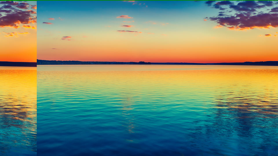 YUV Phaser splitting and displacing color channels to produce prismatic offset and data-driven spatial warping.
Overview
YUV Phaser is a per-channel horizontal displacement engine with data-dependent modulation. It treats each color channel: Y, U, and V: as an independent horizontal delay line, letting you slide them apart by different amounts. The result is a classic chromatic-offset look where color fringes peel away from the source image, reminiscent of misaligned CRT guns or a prism refracting white light into its spectral components.
What makes YUV Phaser special is its displacement controls. Beyond a simple fixed offset, each channel's delay can be modulated by the pixel values themselves: bright pixels shift further than dark ones (or vice versa), producing organic, content-dependent warping that ripples across the image in real time.
A fade-to-color stage sits at the output, allowing the displaced image to be smoothly crossfaded toward black, white, or neutral. Combined with per-channel inversion, YUV Phaser can create everything from subtle chroma separation to extreme spatial distortion and color negative effects.
Start with the Phase knobs alone. Turning a single channel's Phase offset creates the classic RGB-split look instantly. Add Displace to make the split react to image content.
What's In a Name?
The name YUV Phaser describes both the color space and the technique. YUV refers to the luminance (Y) and chrominance (U, V) channels of the video signal. Phaser evokes the idea of shifting each channel's phase: its horizontal position in time: relative to the others, much like a phaser effect in audio shifts the phase of frequency bands to create sweeping comb-filter textures. Here, the "phase" is spatial rather than spectral, but the concept is the same: offset, recombine, and let the interference patterns do the talking.
Quick Start
- Turn U Phase (Knob 2) clockwise to about 25%. The blue-yellow color information slides sideways away from the brightness channel, producing vivid color fringes along vertical edges.
- Now turn V Phase (Knob 3) in the opposite direction. The red-cyan channel displaces in the other direction, creating a full prismatic split.
- Increase U Displace (Knob 5) slowly. Notice how the chroma offset now varies across the image: bright areas shift more than dark areas, creating a wavy, content-dependent distortion.
Parameters
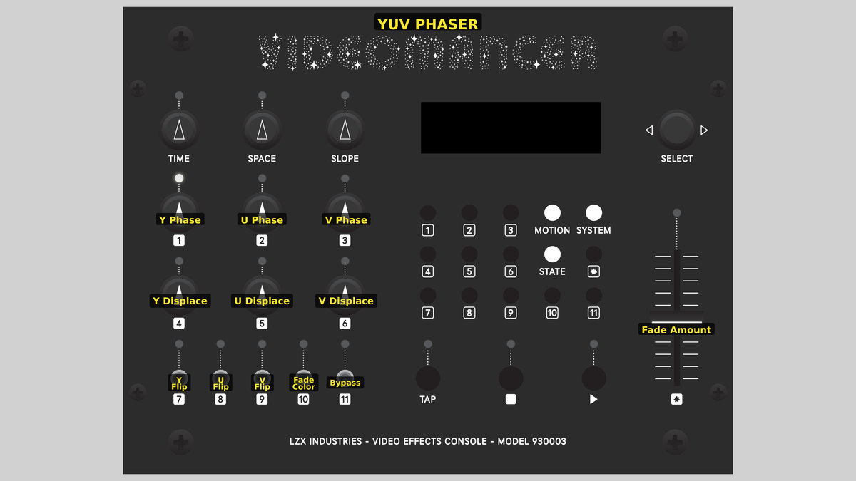 Videomancer's front panel with YUV Phaser active. Knobs 1–6 (top two rows of left cluster), Toggle switches 7–11 (bottom row of left cluster), Fader 12 (right side).
Knob 1 — Y Phase
| Property | Value |
|---|---|
| Range | 0.0 – 1023.0 |
| Default | 0.0 |
Y Phase sets the base horizontal delay for the luminance channel. At 0.0, fully counterclockwise, there is no displacement: the Y channel passes through at its original position. As the value increases, the brightness information shifts further to the right. At maximum, the Y channel is displaced by up to 1023 pixel clocks.
Because Y carries brightness, displacing it while leaving U and V in place makes edges appear to glow or shadow in unexpected directions. Small Y Phase values create the illusion of embossing or bas-relief.
Knob 2 — U Phase
| Property | Value |
|---|---|
| Range | 0.0 – 1023.0 |
| Default | 0.0 |
U Phase sets the base horizontal delay for the U chrominance channel. U encodes the blue-yellow color axis. Displacing U while leaving Y untouched creates blue and yellow color fringes along vertical edges. At 0.0, U is aligned with the other channels. Increasing U Phase slides the blue-yellow information to the right.
For a classic chromatic-aberration look, offset U Phase and V Phase in opposite amounts while leaving Y Phase at zero.
Knob 3 — V Phase
| Property | Value |
|---|---|
| Range | 0.0 – 1023.0 |
| Default | 0.0 |
V Phase sets the base horizontal delay for the V chrominance channel. V encodes the red-cyan color axis. Displacing V independently of U creates asymmetric color splits: instead of a uniform rainbow fringe, each edge gets a different color combination. At 0.0, V is aligned. Increasing V Phase pulls the red-cyan axis to the right.
Knob 4 — Y Displace
| Property | Value |
|---|---|
| Range | 0.0% – 200.0% |
| Default | 0.0% |
Y Displace adds a data-dependent component to the Y channel's delay. The raw pixel brightness is multiplied by this gain and added to the base Y Phase offset. At 0.0%, displacement is zero and only the fixed phase applies. At 200.0%, bright pixels experience significantly more delay than dark ones, warping the luminance channel's horizontal position based on image content.
Displacement is computed from the original input value, not the inverted value. Y Flip affects the data traveling through the delay line but does not change which pixels are displaced further.
Knob 5 — U Displace
| Property | Value |
|---|---|
| Range | 0.0% – 200.0% |
| Default | 0.0% |
U Displace adds data-dependent delay to the U channel. The U pixel value is multiplied by this gain and added to the base U Phase offset. Because U is a chrominance channel centered around 512, the modulation is driven by color content rather than brightness. Areas of strong blue-yellow saturation shift more than neutral areas, creating color-dependent spatial warping.
Knob 6 — V Displace
| Property | Value |
|---|---|
| Range | 0.0% – 200.0% |
| Default | 0.0% |
V Displace adds data-dependent delay to the V channel, following the same logic as U Displace but on the red-cyan axis. Increasing V Displace causes areas with strong red or cyan saturation to shift more than neutral areas.
Setting all three Displace controls to the same high value creates a uniform ripple that follows image structure. Setting them to different values creates per-channel warping, where each color plane distorts independently.
Switch 7 — Y Flip
| Property | Value |
|---|---|
| Off | Off |
| On | On |
| Default | Off |
Y Flip inverts the luminance channel before it enters the delay line. When set to On, bright becomes dark and dark becomes bright: a digital negative of the Y channel only. Because the inversion happens before the delay and fade stages, it affects the content that gets displaced and faded, but not the displacement amount itself (which is computed from the original input).
Switch 8 — U Flip
| Property | Value |
|---|---|
| Off | Off |
| On | On |
| Default | Off |
U Flip inverts the U chrominance channel before the delay line. In YUV color space, inverting U swaps blue and yellow tones. Combined with channel displacement, this creates color-negative fringes that complement the original hues.
Switch 9 — V Flip
| Property | Value |
|---|---|
| Off | Off |
| On | On |
| Default | Off |
V Flip inverts the V chrominance channel before the delay line. Inverting V swaps red and cyan tones. Enable both U Flip and V Flip together to produce a full chroma negative while preserving the original brightness.
Switch 10 — Fade Color
| Property | Value |
|---|---|
| Off | Black |
| On | White |
| Default | Black |
Fade Color selects the target color for the fade-to-color stage. When set to Black, the fade interpolates toward black (Y=0) and neutral chroma (U=512, V=512). When set to White, the fade interpolates toward white (Y=1023) and neutral chroma. In both cases, the chrominance channels fade to their midpoint (neutral gray), so the fade always desaturates.
Switch 11 — Bypass
| Property | Value |
|---|---|
| Off | Off |
| On | On |
| Default | Off |
Bypass routes the unprocessed input signal directly to the output, skipping all displacement, inversion, and fade processing. The sync delay pipeline still aligns timing, so there is no glitch on transition. Use Bypass for instant A/B comparison between the raw input and the processed result.
Fader 12 — Fade Amount
| Property | Value |
|---|---|
| Range | 0.0% – 100.0% |
| Default | 100.0% |
Fade Amount controls the crossfade between the processed (displaced and inverted) signal and the target fade color. At 100.0%, fully up, the processed signal passes through at full strength. At 0.0%, fully down, the output is entirely the fade color (black or white for Y, neutral for U and V). Intermediate positions blend between the two.
The fader defaults to 100.0% (full wet). Pulling it down fades the entire output toward the selected color: it is not a dry/wet mix of displaced vs. undisplaced signal. Use Bypass for a true A/B comparison.
Background
Chromatic aberration
In optics, chromatic aberration occurs when a lens fails to focus all wavelengths of light to the same point. Red, green, and blue components of the image shift relative to one another, creating colored fringes along high-contrast edges. Photographers and cinematographers usually consider this a defect, but in video synthesis it's a deliberate, celebrated aesthetic. YUV Phaser simulates this effect digitally by displacing the Y, U, and V channels by independent pixel counts.
Data-dependent displacement
The Displace controls go beyond fixed offsets. Each channel's delay is computed as:
total_delay = Phase + (pixel_value × Displace) >> 10
The pixel value is the raw 10-bit sample from that channel. The multiplication and right-shift scale the modulation into the 11-bit delay range (0–2047 pixel clocks). Because the delay varies pixel by pixel, the displacement isn't uniform: it follows the contours of the image, producing organic, flowing distortion rather than a rigid slide.
Fade-to-color stage
After displacement, each channel passes through an interpolator that crossfades between the displaced pixel and a target color. For the Y channel, the target is either 0 (black) or 1023 (white), selected by the Fade Color toggle. For the U and V channels, the target is always 512: the neutral midpoint: regardless of the Fade Color setting. This means the fade always desaturates chroma while driving luminance toward the selected extreme.
Signal Flow
Signal Flow Notes
The three channels are fully independent: each has its own delay line, its own delay computation, and its own fade interpolator. The only shared elements are the Fade Color toggle (which sets Y's fade target but doesn't affect U/V) and the Bypass switch.
A subtle but important detail: the displacement modulation uses the original input pixel value (data_in.y, data_in.u, data_in.v), not the inverted value. The Flip toggles invert the data inside the delay line, but the delay amount is always computed from the unmodified input. This means flipping a channel changes its appearance without changing where pixels are spatially displaced.
Pipeline depth is 8 clocks (1 input register + 2 variable delay + 4 interpolator + 1 IO alignment). The sync and bypass paths use matched delay lines so the output is always time-aligned.
Exercises
These exercises progress from basic channel separation to full data-dependent displacement and color manipulation.
Exercise 1: Prismatic Split
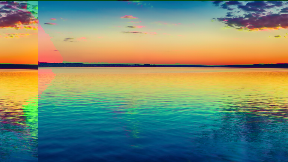 Prismatic Split — simulated result across source images.
Exercise Illustration
A description of the exercise illustration.
Learning Outcomes
Create a classic chromatic-aberration look by offsetting the color channels.
Key Concepts
- Phase controls produce fixed horizontal displacement per channel
- Displacing U and V while leaving Y centered creates color fringes
- Opposite offsets create a symmetric rainbow split
Video Source
A live camera feed or recorded footage with strong vertical edges and contrasting colors.
Steps
- Single channel offset: Turn U Phase (Knob 2) to about 30%. Observe blue-yellow fringes appearing along vertical edges.
- Opposite split: Turn V Phase (Knob 3) to about 30% as well. Now red-cyan fringes appear on the opposite side of edges, creating a full prismatic look.
- Luma offset: Add a small amount of Y Phase (Knob 1), around 10%. The brightness layer shifts, creating a ghostly double-exposure alongside the color fringes.
- Compare: Toggle Bypass (Switch 11) to see the raw input, then toggle back to appreciate the effect.
Settings
| Control | Value |
|---|---|
| Y Phase | ~100 |
| U Phase | ~300 |
| V Phase | ~300 |
| Y Displace | 0.0% |
| U Displace | 0.0% |
| V Displace | 0.0% |
| Y Flip | Off |
| U Flip | Off |
| V Flip | Off |
| Fade Color | Black |
| Bypass | Off |
| Fade Amount | 100.0% |
Exercise 2: Content-Dependent Warping
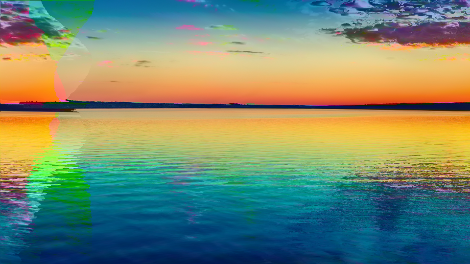 Content-Dependent Warping — simulated result across source images.
Exercise Illustration
A description of the exercise illustration.
Learning Outcomes
Use the Displace controls to create image-driven spatial distortion.
Key Concepts
- Displace adds pixel-value-based modulation to the delay
- Bright areas shift further than dark areas
- Different Displace values per channel create per-color warping
Video Source
Footage with a range of tonal values (faces, landscapes, or text overlays work well.)
Steps
- Prepare: Set U Phase to ~20% and V Phase to ~20% for a slight base offset.
- Add displacement: Increase Y Displace (Knob 4) to about 100%. Bright areas of the luminance channel stretch and smear sideways.
- Chroma displacement: Now increase U Displace (Knob 5) to about 80% and V Displace (Knob 6) to about 120%. Each color channel warps differently based on its own content, creating fluid, multicolored distortion.
- Animate: Slowly sweep Y Displace from minimum to maximum. The distortion flows organically through the image, following brightness contours.
- Invert and compare: Toggle Y Flip (Switch 7). The brightness inverts but the displacement pattern stays the same (note the visual difference.)
Settings
| Control | Value |
|---|---|
| Y Phase | 0.0 |
| U Phase | ~200 |
| V Phase | ~200 |
| Y Displace | 100.0% |
| U Displace | 80.0% |
| V Displace | 120.0% |
| Y Flip | Off |
| U Flip | Off |
| V Flip | Off |
| Fade Color | Black |
| Bypass | Off |
| Fade Amount | 100.0% |
Exercise 3: Color Negative Fade
 Color Negative Fade — simulated result across source images.
Exercise Illustration
A description of the exercise illustration.
Learning Outcomes
Combine channel inversion with the fade stage for surreal color-negative compositions.
Key Concepts
- Flip toggles invert individual channels before processing
- Inverting U and V together creates a chroma negative
- The fade stage desaturates toward neutral, blending processed and target colors
Video Source
High-saturation footage (flowers, neon signs, or colorful graphics.)
Steps
- Chroma negative: Enable U Flip (Switch 8) and V Flip (Switch 9). Colors swap to their complements (reds become cyan, blues become yellow.)
- Add displacement: Set U Phase to ~15% and V Phase to ~15% for a subtle offset. The inverted color fringes create an eerie, otherworldly split.
- Fade toward white: Set Fade Color (Switch 10) to White. Pull Fade Amount (Fader 12) down to about 60%. The image begins to wash out toward white, with the inverted colors blending into a high-key pastel palette.
- Full negative: Now enable Y Flip (Switch 7) as well. The entire image is color-inverted and partially faded, creating a dreamy photographic-negative composition.
- Sweep the fade: Slowly move the Fade Amount fader from 100% down to 0%. The displaced, inverted image dissolves into pure white.
Settings
| Control | Value |
|---|---|
| Y Phase | 0.0 |
| U Phase | ~150 |
| V Phase | ~150 |
| Y Displace | 0.0% |
| U Displace | 0.0% |
| V Displace | 0.0% |
| Y Flip | On |
| U Flip | On |
| V Flip | On |
| Fade Color | White |
| Bypass | Off |
| Fade Amount | 60.0% |
Glossary
-
BRAM: Block RAM; dedicated memory blocks inside the FPGA used to implement delay lines and lookup tables.
-
Chromatic Aberration: An optical defect where different wavelengths of light focus at different points, causing colored fringes; simulated digitally by offsetting color channels.
-
Chrominance: The color information in a video signal, encoded as U (blue-yellow axis) and V (red-cyan axis) in YUV color space.
-
Delay Line: A buffer that holds samples and plays them back after a configurable number of clock cycles, producing a horizontal spatial offset.
-
Displacement: A per-pixel variation in delay amount, driven by the pixel's own value, creating content-dependent spatial distortion.
-
Interpolator: A hardware module that crossfades between two values based on a mixing parameter; used here for fade-to-color blending.
-
Luminance: The brightness component (Y) of a YUV video signal, representing perceived lightness independent of color.
-
Phase: A fixed horizontal offset applied to a channel, measured in pixel clocks; shifts the channel's spatial position relative to the others.
-
Variable Delay: A delay line whose depth changes dynamically on a per-sample basis, enabling data-dependent spatial effects.
-
YUV: A color space separating luminance (Y) from chrominance (U, V), allowing independent processing of brightness and color.