Mycelium
 Mycelium cultivating luminous reaction-diffusion networks that emerge, branch, and decay across the video frame.
Overview
Mycelium is a self-generating video texture synthesizer based on a three-species reaction-diffusion system. Unlike processing programs that transform an input signal, Mycelium grows its own organic visual content: branching networks of luminous filaments that emerge, spread, and decay in real time. Input video serves as a seed, determining where and how aggressively new growth begins.
The simulation models three interacting chemical species: an activator (U) that drives the expanding growth front, an inhibitor (V) that trails behind depleting resources, and a persistent network species (W) that accumulates wherever growth has occurred. Together, these species produce patterns reminiscent of fungal mycelium, lichen, coral, or the dendritic branching of neurons. The balance between Feed Rate and Kill Rate determines whether the system produces isolated spots, labyrinthine stripes, or chaotic turbulence.
Mycelium generates imagery autonomously: you don't need an input signal to create patterns. Input video acts as a catalyst: brighter areas seed new growth. Without input, the built-in noise source provides sparse background seeding.
What's In a Name?
Mycelium is the root network of a fungus: a vast, branching web of threadlike filaments called hyphae that grow outward from a central point, branching and reconnecting as they explore their environment. The visual patterns produced by this program mirror that growth: luminous strands emerge from seed points, branch outward, and leave behind a persistent network map of all past activity. The name reflects both the biological appearance of the output and the underlying mathematics: growth, branching, memory.
Quick Start
- With default settings, observe the screen. Organic patterns emerge and evolve from sparse background seeding by a built-in noise source. Give the simulation a few seconds to develop.
- Turn Color Map (Knob 5) to explore different palettes: from monochrome to bioluminescent amber, magenta, indigo, or forest green.
- Adjust Feed Rate (Knob 1) and Kill Rate (Knob 2) together. Small changes shift the system between spots, stripes, and turbulent patterns. These two knobs define the character of the simulation.
- Connect a video source and increase Seed Thresh (Knob 4). The reaction-diffusion growth follows the bright contours of your input image.
Parameters
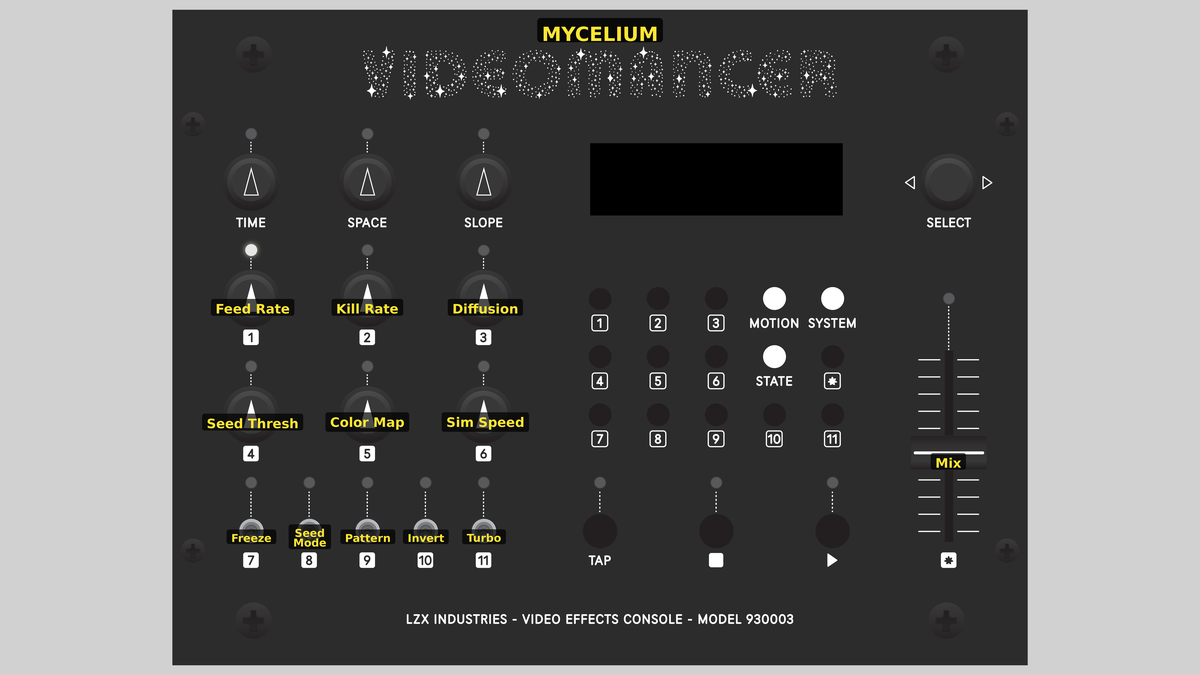 Videomancer's front panel with Mycelium active. Knobs 1–6 (top two rows of left cluster), Toggle switches 7–11 (bottom row of left cluster), Fader 12 (right side).
Knob 1 — Feed Rate
| Property | Value |
|---|---|
| Range | 0.0% – 100.0% |
| Default | 39.1% |
Feed Rate controls the strength of the activator source: how quickly new activator chemical is replenished in the simulation. This corresponds to F in the Gray-Scott reaction-diffusion equations. At low values, the activator replenishes slowly, producing sparse, isolated patterns. As Feed Rate increases, the activator supply strengthens and patterns grow more densely, filling the frame with branching networks. At extreme values, the simulation can become uniformly saturated.
Feed Rate and Kill Rate are deeply coupled. Moving one without adjusting the other can push the simulation into a featureless steady state. Explore them together to find the narrow boundary where interesting patterns live.
Knob 2 — Kill Rate
| Property | Value |
|---|---|
| Range | 0.0% – 100.0% |
| Default | 54.7% |
Kill Rate controls how quickly the inhibitor drains away: the k parameter in the Gray-Scott equations. Low Kill Rate means the inhibitor persists, suppressing activator growth and producing broad, slow-moving patterns. High Kill Rate means the inhibitor is consumed faster, allowing the activator to grow more aggressively and producing finer, more turbulent textures. The balance between Feed Rate and Kill Rate determines the overall character of the pattern: spots, stripes, waves, or chaos.
Knob 3 — Diffusion
| Property | Value |
|---|---|
| Range | 0.0% – 100.0% |
| Default | 50.0% |
Diffusion controls how far each species spreads spatially per simulation step, determining the spatial scale of the patterns. At low values, diffusion is weak and patterns remain compact with fine features. At high values, diffusion is strong and patterns become broader, smoother, and more slowly evolving. The Pattern toggle (Switch 9) determines the ratio between activator and inhibitor diffusion rates.
Low Diffusion with moderate Feed and Kill rates produces crisp, high-contrast networks with sharp edges. High Diffusion produces softer, more painterly textures.
Knob 4 — Seed Thresh
| Property | Value |
|---|---|
| Range | 0.0% – 100.0% |
| Default | 50.0% |
Seed Thresh controls the luminance threshold for video-driven seeding. When the brightness of the input video exceeds this threshold, new inhibitor is injected at that pixel, triggering a local reaction-diffusion event. At low values, only the very brightest areas of the input seed growth. As Seed Thresh increases toward 100%, the threshold drops and progressively dimmer areas trigger seeding, causing the simulation to follow more of the input image's structure.
This parameter also controls the rate at which the network species (W) accumulates, so higher values produce both more aggressive seeding and faster network buildup.
Knob 5 — Color Map
| Property | Value |
|---|---|
| Range | 0.0% – 100.0% |
| Default | 50.0% |
Color Map selects one of eight color palettes for rendering the three-species simulation. The palette maps species concentrations to YUV color. Sweep the knob from left to right to cycle through:
- Monochrome: Neutral luminance, no chroma
- Amber: Bioluminescent orange glow
- Magenta: Warm pink-purple
- Indigo: Deep blue-violet
- Cyan: Bioluminescent aqua
- Green: Forest moss
- Gold: Warm ochre
- Triplex: All three species encoded directly into Y, U, and V channels
Knob 6 — Sim Speed
| Property | Value |
|---|---|
| Range | 0.0% – 100.0% |
| Default | 50.0% |
Sim Speed controls the decay rate of the persistent network species (W). At low values, the network fades very slowly, accumulating a dense historical record of all past growth. At high values, the network fades rapidly, showing only recent activity. This parameter shapes the visual "memory" of the simulation: how long the luminous strand trails persist after the active growth front has moved on.
Switch 7 — Freeze
| Property | Value |
|---|---|
| Off | Off |
| On | On |
| Default | Off |
Freeze halts the simulation. When enabled, the reaction-diffusion equations stop updating and the current pattern is held indefinitely. All three species retain their state. Disable Freeze to resume evolution from the frozen state. Use Freeze to capture an interesting moment and study the pattern's static structure.
Switch 8 — Seed Mode
| Property | Value |
|---|---|
| Off | Cont. |
| On | One-Shot |
| Default | Cont. |
Seed Mode selects between Cont. (Continuous) and One-Shot seeding. In Continuous mode, input video seeds new growth every frame wherever the luminance exceeds the threshold. In One-Shot mode, seeding occurs only once per frame: the first qualifying pixel latches the seed, and all subsequent pixels that frame are ignored. The latch resets on each vertical sync. One-Shot produces a single localized burst of growth per frame, while Continuous produces a distributed pattern that closely follows the input image.
Switch 9 — Pattern
| Property | Value |
|---|---|
| Off | Spots |
| On | Stripes |
| Default | Spots |
Pattern selects between Spots and Stripes diffusion regimes. This toggle controls the ratio between the activator's and inhibitor's diffusion rates. In Spots mode, the activator diffuses significantly faster than the inhibitor (two stops of difference), producing isolated circular features. In Stripes mode, the diffusion rates are closer (one stop of difference), producing labyrinthine, interconnected stripe patterns.
This is the Turing instability: the fundamental mechanism of reaction-diffusion pattern formation. Different diffusion ratios create qualitatively different patterns, just as Alan Turing predicted in 1952.
Switch 10 — Invert
| Property | Value |
|---|---|
| Off | Off |
| On | On |
| Default | Off |
Invert switches the display emphasis between two rendering modes. In the Off position, the output shows UV Tips mode: the inhibitor species (V) dominates luminance, highlighting the active reaction fronts: the bright edges where growth is currently happening. In the On position, the output switches to Web mode: the network species (W) dominates luminance, revealing the persistent strand map: the accumulated history of where growth has been.
Switch 11 — Turbo
| Property | Value |
|---|---|
| Off | Off |
| On | On |
| Default | Off |
Turbo inverts all three species in the color mapping stage. When enabled, the activator, inhibitor, and network values are complemented before rendering. This produces a photographic negative of the pattern: dark areas become bright, background becomes foreground. Combined with different Color Map palettes, Turbo can dramatically change the visual character of the output.
Fader 12 — Mix
| Property | Value |
|---|---|
| Range | 0.0% – 100.0% |
| Default | 100.0% |
Mix crossfades between the input video signal (dry) and the reaction-diffusion output (wet). At 0%, the output is pure dry input. At 100%, the output is pure synthesized imagery. Intermediate values blend the two, superimposing the organic patterns over the input video. Mix defaults to 100% since Mycelium is a synthesis program designed to generate its own visual content.
Background
Reaction-Diffusion Systems
In 1952, the mathematician Alan Turing published a paper titled "The Chemical Basis of Morphogenesis," proposing that patterns in biology: spots on a leopard, stripes on a zebrafish, the branching of coral: could emerge from the interaction of two chemicals that diffuse at different rates. One chemical activates growth; the other inhibits it. When the activator diffuses faster than the inhibitor, a Turing instability occurs: small random fluctuations amplify into stable, self-organizing patterns.
The Gray-Scott model is one of the best-studied implementations of Turing's idea. It describes two interacting species governed by two parameters: feed rate (F), which replenishes the activator, and kill rate (k), which drains the inhibitor. Depending on the balance between F and k, the system produces an extraordinary variety of stable patterns: spots, stripes, spirals, replicating dots, and chaotic turbulence.
Three-Species Extension
Mycelium extends the classical two-species Gray-Scott model with a third species: the network accumulator (W). In biological terms, W represents the persistent hyphal network: the established structure left behind after the active growth front has passed. W accumulates proportionally to inhibitor concentration and decays slowly over time. This gives the simulation a visual memory: the network of luminous strands traces the history of all past growth events.
The three species interact through spatial coupling (diffusion via an approximate Laplacian computed from three neighbors: left, north, and northwest) and through the reaction kinetics. U and V follow the standard Gray-Scott equations with full-precision Radix-4 Booth multipliers computing v² and u·v². W uses shift-based arithmetic for its growth and decay, requiring no additional multipliers.
Seeding and Autonomous Operation
Mycelium seeds its simulation through two complementary mechanisms. The primary path compares input video luminance against a threshold derived from Seed Thresh: when a pixel exceeds the threshold, its luminance value is injected directly as the inhibitor species, triggering a local reaction event. The secondary path is an autonomous LFSR (linear feedback shift register) noise source that provides sparse, random seeding across the frame. This ensures patterns emerge even without any video input connected. The Seed Mode toggle selects whether seeding is continuous (every qualifying pixel, every frame) or one-shot (first qualifying pixel per frame only).
Signal Flow
Signal Flow Notes
The simulation core runs three parallel species updates using shared line buffers and a common Laplacian computation. The critical path is the U and V update, which requires two sequential 8-cycle multiplier stages for v² and u·v². The W species avoids this bottleneck entirely: its growth and decay are computed with shift operations in Stage 2 and written back via a separate 2-clock address pipe, finishing 20 clocks before U and V.
Seeding occurs after the UV assembly stage. Input luminance is compared against a threshold derived from Seed Thresh: higher knob values lower the threshold, admitting more of the input image. When exceeded, the input luminance directly replaces the computed V value at that pixel, injecting a burst of inhibitor that triggers a local reaction event. The LFSR provides sparse background seeding for autonomous operation.
Feed Rate and Kill Rate define the pattern. The simulation lives on a narrow boundary in parameter space: small adjustments produce qualitatively different behaviors. Think of these two knobs as tuning a radio: most of the dial is static, but the interesting textures live in the narrow bands between.
Exercises
These exercises explore the three-species reaction-diffusion system from autonomous pattern generation through video-seeded growth to network visualization.
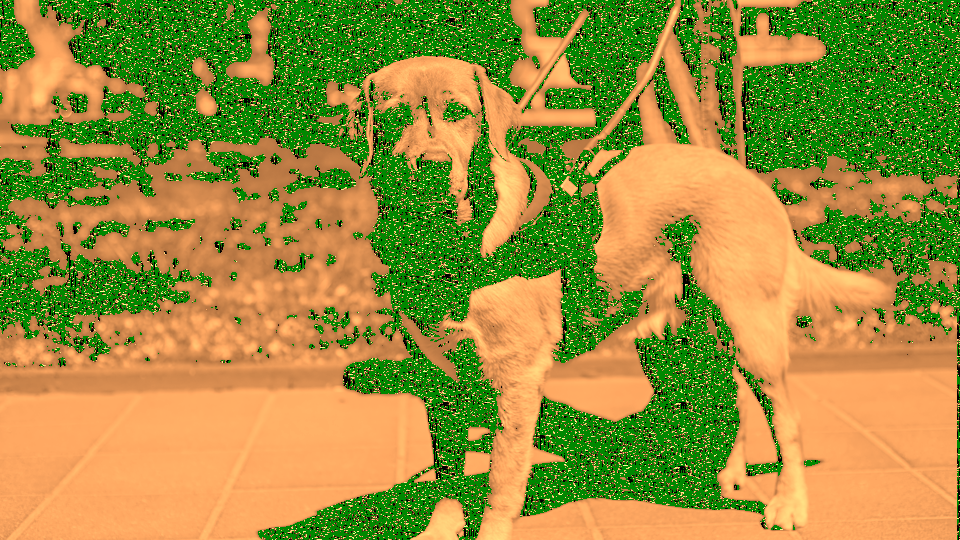
Exercise 1: Autonomous Pattern Growth
 Autonomous Pattern Growth — simulated result across source images.
Exercise Illustration
A description of the exercise illustration.
Learning Outcomes
Observe how Feed Rate and Kill Rate interact to produce different pattern types without any input video.
Key Concepts
- Gray-Scott parameters F and k define pattern morphology
- The Pattern toggle changes diffusion ratios for spots vs. stripes
- Species evolve autonomously from sparse LFSR noise seeding
Steps
- Watch emergence: Start with all defaults. Observe patterns emerging from the noise floor (sparse spots or stripes gradually appear and grow.)
- Increase growth rate: Slowly increase Feed Rate (Knob 1) while keeping Kill Rate (Knob 2) steady. Watch patterns grow denser and more active.
- Finer turbulence: Now slowly increase Kill Rate. The patterns become finer and more turbulent as the inhibitor drains faster.
- Spots vs stripes: Toggle Pattern (Switch 9) between Spots and Stripes. In Spots mode, isolated circular features dominate. In Stripes mode, patterns connect into labyrinthine networks.
- Freeze the moment: Toggle Freeze (Switch 7) to halt the simulation. Study the frozen pattern structure. Unfreeze to resume.
Settings
| Control | Value |
|---|---|
| Feed Rate | ~40% |
| Kill Rate | ~55% |
| Diffusion | 50% |
| Seed Thresh | ~20% |
| Color Map | ~15% (Amber) |
| Sim Speed | 50% |
| Freeze | Off |
| Seed Mode | Cont. |
| Pattern | Spots |
| Invert | Off |
| Turbo | Off |
| Mix | 100% |
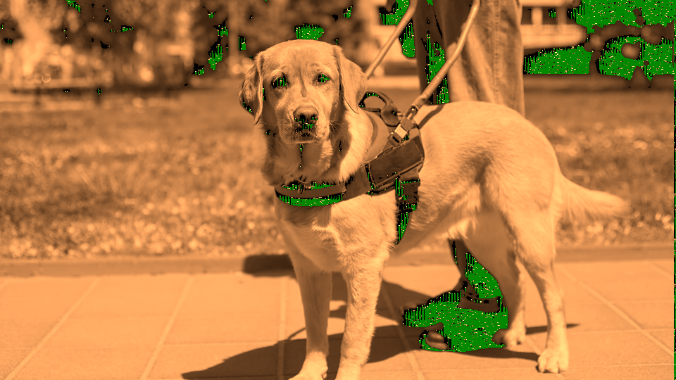
Exercise 2: Video-Seeded Growth
 Video-Seeded Growth — simulated result across source images.
Exercise Illustration
A description of the exercise illustration.
Learning Outcomes
Use input video luminance to control where reaction-diffusion patterns emerge.
Key Concepts
- Input luminance seeds inhibitor injection above a threshold
- Seed Thresh controls how much of the input image triggers growth
- One-Shot mode produces localized bursts vs. Continuous distributed seeding
Steps
- Connect a source: Connect a video source showing a recognizable subject with varied brightness.
- Seed from brightness: Increase Seed Thresh (Knob 4) until patterns begin appearing where the input video is bright. Growth follows the bright contours of the input image.
- Single-burst seeding: Switch Seed Mode (Switch 8) to One-Shot. Notice how seeding becomes a single burst per frame rather than continuous injection (patterns grow outward from a single seed point.)
- Flood the threshold: Switch back to Cont. and slowly raise Seed Thresh further. Progressively dimmer areas begin producing growth. At high values, nearly the entire image seeds the simulation.
- Overlay on source: Adjust Mix (Fader 12) to blend the synthesized pattern over the original input video.
Settings
| Control | Value |
|---|---|
| Feed Rate | ~40% |
| Kill Rate | ~55% |
| Diffusion | 50% |
| Seed Thresh | ~60% |
| Color Map | ~30% (Magenta) |
| Sim Speed | 50% |
| Freeze | Off |
| Seed Mode | Cont. |
| Pattern | Stripes |
| Invert | Off |
| Turbo | Off |
| Mix | ~70% |
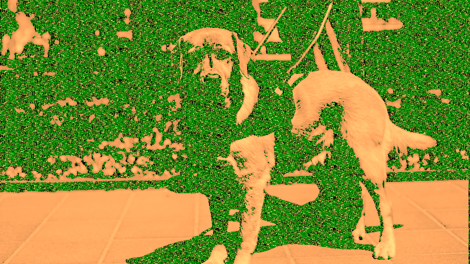
Exercise 3: Network Memory Visualization
 Network Memory Visualization — simulated result across source images.
Exercise Illustration
A description of the exercise illustration.
Learning Outcomes
Explore the network species (W) and how Invert, Turbo, and Sim Speed reveal the simulation's history.
Key Concepts
- The W species accumulates a persistent map of past growth
- Invert toggle switches between active fronts and network history
- Sim Speed controls how quickly the network fades
Steps
- Grow the network: Set moderate Feed Rate and Kill Rate to produce active patterns. Let the simulation run for several seconds to build up network history.
- Reveal the web: Toggle Invert (Switch 10) to On. The display now emphasizes W: the persistent strand network rather than the active growth fronts. The luminous web shows everywhere growth has been.
- Tune persistence: Adjust Sim Speed (Knob 6). At low values, the network persists for a long time, building up a dense historical map. At high values, the network fades quickly, showing only recent growth.
- Photographic negative: Enable Turbo (Switch 11). All three species invert: dark background becomes bright, bright patterns become dark. Combined with different Color Map palettes, this produces dramatic visual shifts.
- Palette exploration: Sweep Color Map (Knob 5) through all eight palettes while in Web mode with Turbo enabled.
Settings
| Control | Value |
|---|---|
| Feed Rate | ~40% |
| Kill Rate | ~55% |
| Diffusion | 50% |
| Seed Thresh | ~50% |
| Color Map | ~60% (Cyan) |
| Sim Speed | ~30% |
| Freeze | Off |
| Seed Mode | Cont. |
| Pattern | Spots |
| Invert | On |
| Turbo | On |
| Mix | 100% |
Glossary
-
Activator: The fast-diffusing species (U) in the Gray-Scott system that drives the expanding growth front.
-
Diffusion: The spatial spreading of a chemical species to neighboring pixels, creating spatial coupling in the simulation.
-
Feed Rate: The Gray-Scott parameter F that controls how quickly the activator is replenished from a background reservoir.
-
Gray-Scott Model: A two-species reaction-diffusion system producing self-organizing patterns from the interaction of an activator and inhibitor.
-
Inhibitor: The slower-diffusing species (V) that depletes resources behind the activator front, creating pattern boundaries.
-
Kill Rate: The Gray-Scott parameter k that controls how quickly the inhibitor drains away.
-
Laplacian: A spatial operator measuring how a value at a point differs from its neighbors; drives diffusion in the simulation.
-
LFSR: Linear Feedback Shift Register; a digital noise source used for autonomous sparse seeding of the simulation.
-
Network Species: The third species (W) unique to Mycelium: a persistent accumulator tracking where growth has occurred.
-
Reaction-Diffusion: A class of mathematical systems where interacting chemicals diffuse at different rates, producing self-organizing spatial patterns.
-
Seeding: Injecting inhibitor at specific pixels to initiate local reaction-diffusion events, controlled by input video luminance or LFSR noise.
-
Turing Instability: The mechanism by which different diffusion rates between activator and inhibitor amplify small fluctuations into stable spatial patterns.