Moiré
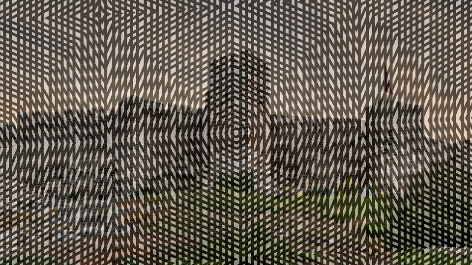
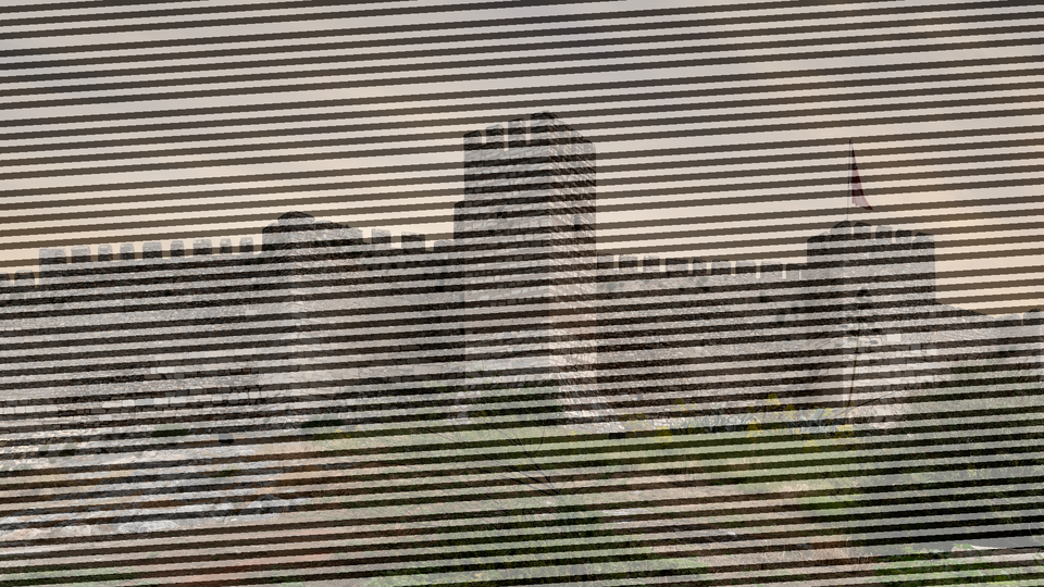 Moire overlaying sinusoidal interference rings on a live video input, creating luminous rippling textures from two rotating grid layers.
Overview
Moire generates smooth sinusoidal interference patterns by superimposing two independently configurable grid layers: circles, ellipses, arcs, and sine waves: and blending the result with an incoming video signal. The two grids each have adjustable pitch and rotation angle. Where their periodic structures overlap, the characteristic moiré fringes emerge: sweeping curves, pulsing rings, and shimmering corridors of light that shift dramatically with even small parameter changes.
Moire produces pure grayscale patterns in its synthesis path and crossfades them with the input video through the Mix fader. At full mix, Moire acts as a standalone pattern synthesizer. At partial mix, the interference texture overlays the source footage, adding rhythmic structure and luminous depth. With the Video Mod control engaged, the input video's brightness bends the spacing of Grid B, locking the moiré fringes to the image content.
Even tiny adjustments to Pitch or Angle create dramatic changes in moiré patterns. Move the knobs slowly (the interference fringes sweep and reshape in real time.)
What's In a Name?
The word moiré comes from the French for "watered," originally describing the shimmering, rippled finish seen on watered silk fabric. That finish is itself an interference pattern: created when two layers of woven thread overlap at a slight angle. Videomancer's Moire program recreates the same phenomenon digitally, superimposing two sinusoidal grids to produce those luminous, shifting fringes on screen.
Quick Start
- Set Pitch A (Knob 1) and Pitch B (Knob 4) to different positions. Two sets of concentric rings appear, and where they overlap, bold moiré fringes form.
- Slowly rotate Angle A (Knob 2). The first grid tilts and the interference fringes sweep across the screen.
- Toggle Grid A (Switch 7) to Ellipse. The circular rings stretch into ovals and the fringe pattern reshapes completely.
- Increase Anim Speed (Knob 6) to add a slow drift. The rings pulse outward and the moiré fringes glide smoothly across the frame.
Parameters
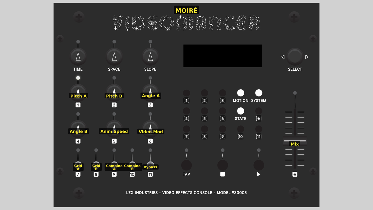 Videomancer's front panel with Moire active. Knobs 1–6 (top two rows of left cluster), Toggle switches 7–11 (bottom row of left cluster), Fader 12 (right side).
Knob 1 — Pitch A
| Property | Value |
|---|---|
| Range | 4px – 64px |
| Default | 12px |
Pitch A sets the spatial frequency of Grid A: how tightly packed the sinusoidal ripples are. At its lowest step, the rings are wide and few, producing broad moiré fringes. At its highest step, the rings are tightly packed, producing fine, dense interference patterns. The control steps through eight discrete frequency values, each roughly doubling the ring density. When Fine (Switch 11) is enabled, all frequencies are doubled, pushing the pattern into even tighter detail.
Knob 2 — Angle A
| Property | Value |
|---|---|
| Range | 0° – 180° |
| Default | 0° |
Angle A rotates Grid A across a 180° range. Even a small rotation creates dramatic changes in the interference fringes where Grid A overlaps Grid B. Because moiré patterns are exquisitely sensitive to angular relationships, this control produces sweeping, organic transformations. The rotation is computed using a 32-entry trigonometric lookup table, giving 16 discrete angle steps.
Knob 3 — Video Mod
| Property | Value |
|---|---|
| Range | 0% – 100% |
| Default | 0% |
Video Mod controls how strongly the input video's luminance bends Grid B's spatial position. At 0%, Grid B is unaffected by the input: the moiré pattern is purely geometric. As Video Mod increases, bright areas of the input image push Grid B's coordinates sideways, warping the concentric rings and locking the moiré fringes to the video content. At full strength, the interference pattern becomes a luminance-driven distortion field.
Video Mod only affects Grid B. Grid A remains geometrically pure regardless of the input signal.
Knob 4 — Pitch B
| Property | Value |
|---|---|
| Range | 4px – 64px |
| Default | 24px |
Pitch B sets the spatial frequency of Grid B independently of Grid A. The interplay between the two pitch values is the primary driver of moiré fringe spacing: when the pitches are close, broad fringes appear; when they differ widely, fine fringes dominate. Like Pitch A, this control offers eight frequency steps, doubled when Fine is active.
Try setting Pitch A and Pitch B to adjacent steps. The slight frequency difference produces slow, sweeping beat frequency fringes: the visual equivalent of two musical notes creating a slow pulsation.
Knob 5 — Angle B
| Property | Value |
|---|---|
| Range | 0° – 180° |
| Default | 120° |
Angle B rotates Grid B independently across 180°. The angular difference between Grid A and Grid B determines the orientation and curvature of the moiré fringes. When both angles are identical, the fringes form straight parallel bands. As the angles diverge, the fringes curve into arcs and hyperbolic shapes.
Knob 6 — Anim Speed
| Property | Value |
|---|---|
| Range | 0% – 100% |
| Default | 0% |
Anim Speed controls the rate of a per-frame animation drift applied to both grids simultaneously. At 0%, the pattern is static. As the value increases, the sinusoidal rings pulse outward from the center at an accelerating rate. The animation uses a direct digital synthesis accumulator that increments phase once per video frame, producing perfectly smooth, jitter-free motion.
Switch 7 — Grid A
| Property | Value |
|---|---|
| Off | Sine |
| On | Ellipse |
| Default | Sine |
Grid A selects between two geometric modes for the first grid layer. In the Sine position, Grid A produces sinusoidal stripes: parallel bands that run perpendicular to the rotation angle. In the Ellipse position, Grid A produces concentric elliptical ripples by stretching the Y axis 2:1 before computing radial distance. Ellipses interact with Grid B's circles to create richer, more asymmetric moiré structures.
Switch 8 — Grid B
| Property | Value |
|---|---|
| Off | Circles |
| On | Arcs |
| Default | Circles |
Grid B selects between two geometric modes for the second grid layer. In the Circles position, Grid B produces concentric circular ripples radiating from the screen center. In the Arcs position, a smooth cosine window fades the lower half of the circles to black, leaving only the upper arcs visible: directional moiré fringes that flow in one direction rather than radiating symmetrically.
Switch 9 — Combine A
| Property | Value |
|---|---|
| Off | Multiply |
| On | Add |
| Default | Multiply |
Combine A selects one axis of the combination mode. Together with Combine B (Switch 10), this toggle selects one of four smooth interference algorithms: see the Toggle Group Notes table below for the full matrix. In the Multiply position, the algorithm emphasizes contrast and dark fringes. In the Add position, the algorithm shifts toward brighter, averaged blends.
Switch 10 — Combine B
| Property | Value |
|---|---|
| Off | Diff |
| On | Min |
| Default | Diff |
Combine B selects the other axis of the combination mode. In the Diff position, the algorithm uses difference-based operations that create high-contrast interference fringes. In the Min position, the algorithm uses softer, shadow-like calculations. The final mode depends on both toggles together: consult the Toggle Group Notes table for the exact behavior of each combination.
Switch 11 — Fine
| Property | Value |
|---|---|
| Off | Off |
| On | On |
| Default | Off |
Fine doubles the spatial frequency of both grids simultaneously. When set to On, all eight pitch steps are shifted upward by one octave, producing patterns with twice the ring density. This is useful for creating tighter, more intricate moiré textures without changing the pitch ratio between the two grids.
At high pitch settings with Fine enabled, the pattern can exceed the display's pixel resolution, producing aliased artifacts. This is sometimes a desirable visual effect.
Switches 9 and 10 form a two-bit mode selector that chooses one of four combination algorithms:
| Combine A | Combine B | Mode | Character |
|---|---|---|---|
| Multiply | Diff | Multiply | Dark fringes, high contrast |
| Add | Diff | Additive | Bright, averaged blend |
| Multiply | Min | Soft Difference | Classic moiré fringes |
| Add | Min | Soft Minimum | Shadow intersections |
Fader 12 — Mix
| Property | Value |
|---|---|
| Range | 0% – 100% |
| Default | 100% |
Mix crossfades between the dry input video and the wet moiré pattern. At 0% (fully left), only the original input passes through. At 100% (fully right), only the pure moiré synthesis is visible: a grayscale pattern with neutral chroma. Intermediate positions blend the moiré texture over the input video, creating luminous overlays where the sinusoidal rings modulate the source image.
Background
Moiré interference
A moiré pattern forms wherever two periodic structures overlap at a slight offset. The effect is familiar from everyday life: two chain-link fences viewed one behind the other, overlapping window screens, or the shimmering bands that appear when you photograph a striped shirt on a digital camera. In each case, the interaction between two regular grids produces a third, larger-scale pattern that wasn't present in either grid alone.
The mathematics behind moiré fringes is the same as acoustic beats: when two frequencies are close but not identical, their sum contains a slow oscillation at the difference frequency. In audio, you hear a pulsing volume. In video, you see sweeping bands of light and dark. Moire exploits this principle by generating two sinusoidal grids with controllable frequency and angle, then combining them to make the interference fringes visible.
Sinusoidal smoothness
Unlike hard-edged square-wave patterns, Moire's grids use a 256-entry sine lookup table stored in a single iCE40 block RAM. The radial distance from the screen center (computed via an alpha-max-beta-min fast approximation) is multiplied by the spatial frequency, and the result indexes into the sine table. This produces perfectly smooth concentric ripples with no hard edges. The sine function also naturally masks the small (~3%) octagonal error in the distance approximation, since it maps any continuous input to a smooth curve.
Coordinate rotation
Each grid's angle is applied by rotating the screen coordinates through a 2D rotation matrix. The sine and cosine values for the rotation come from a compact 32-entry trigonometric lookup table embedded directly in logic. The rotation gives each grid 16 discrete angle steps across a 180° range. Because moiré patterns are extremely sensitive to angular alignment, even a single step change produces a visible transformation of the fringe geometry.
Signal Flow
Signal Flow Notes
Two key architectural choices shape the sound of this program:
-
Dual-path grid generation: Grid A and Grid B are computed in parallel from the same screen coordinates but with independent rotation, shape selection, and pitch. They share the same 256-entry BRAM sine table via true dual-port read, so both lookups happen in the same clock cycle.
-
Video modulation on Grid B only: The input video's luminance offsets Grid B's rotated X coordinate before the distance computation. This means Grid A remains geometrically rigid while Grid B warps dynamically with the image content. The asymmetry creates a moiré pattern that is partly fixed and partly content-reactive.
The combination mode matters. Multiply and Min produce dark fringes (where patterns cancel). Add and Diff produce bright fringes (where patterns reinforce). Experiment with all four modes on the same pitch/angle settings to see how radically the fringe character changes.
Exercises
These exercises build from basic ring interference to animated, video-modulated moiré textures. Each one adds a new dimension to the pattern.
Exercise 1: Beat Frequency Fringes
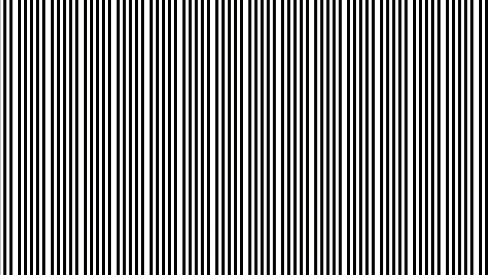 Beat Frequency Fringes — simulated result across source images.
Exercise Illustration
A description of the exercise illustration.
Learning Outcomes
Discover how small pitch differences between the two grids create large-scale moiré fringes.
Key Concepts
- Moiré fringes emerge from the frequency difference between two grids
- Close pitch values → broad fringes; distant values → fine fringes
- Angle offset determines fringe curvature
Video Source
Any video input, or no input with Mix fully clockwise.
Steps
- Match the grids: Set Pitch A (Knob 1) and Pitch B (Knob 4) to the same step. The two grids cancel almost perfectly, producing a nearly uniform field.
- Offset one step: Move Pitch B one step clockwise. Bold, sweeping moiré fringes appear (these are the beat frequency between the two grids.)
- Add angle: Slowly rotate Angle A (Knob 2) away from zero. The straight fringes curve into arcs and hyperbolic shapes.
- Widen the gap: Move Pitch B farther from Pitch A. The fringes become finer and more numerous as the frequency difference increases.
- Try Fine: Enable Fine (Switch 11) to double both frequencies. The overall ring density increases, but the pitch ratio stays the same, so the moiré fringe spacing is preserved.
Settings
| Control | Value |
|---|---|
| Pitch A | Step 3 (~8 px) |
| Angle A | 0° |
| Video Mod | 0% |
| Pitch B | Step 4 (~12 px) |
| Angle B | 0° |
| Anim Speed | 0% |
| Grid A | Sine |
| Grid B | Circles |
| Combine A | Multiply |
| Combine B | Diff |
| Fine | Off |
| Mix | 100% |
Exercise 2: Animated Ellipses and Arcs
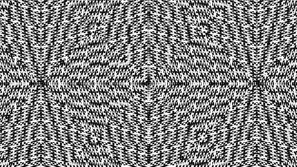 Animated Ellipses and Arcs — simulated result across source images.
Exercise Illustration
A description of the exercise illustration.
Learning Outcomes
Layer different geometric shapes and add animation drift.
Key Concepts
- Ellipses stretch the Y axis before distance computation
- Arcs use a cosine fade to clip circles to a hemisphere
- Animation drift smoothly shifts the phase of both grids
Video Source
A static image or test pattern with strong horizontal and vertical features.
Steps
- Elliptical Grid A: Set Grid A to Ellipse (Switch 7). The concentric rings flatten into ovals, changing the fringe topology.
- Arc Grid B: Set Grid B to Arcs (Switch 8). The lower half of Grid B's circles fades smoothly away, leaving semicircular arcs that interact asymmetrically with Grid A's ellipses.
- Angle both grids: Set Angle A to about 45° and Angle B to about 120°. The tilted ellipses and arcs produce complex, non-repeating fringe corridors.
- Animate: Increase Anim Speed (Knob 6) to about 30%. The rings pulse outward and the moiré fringes glide slowly across the frame.
- Try Additive: Set Combine A to Add (Switch 9). The fringes brighten and the overall texture becomes more luminous.
Settings
| Control | Value |
|---|---|
| Pitch A | Step 4 (~12 px) |
| Angle A | ~45° |
| Video Mod | 0% |
| Pitch B | Step 5 (~16 px) |
| Angle B | ~120° |
| Anim Speed | ~30% |
| Grid A | Ellipse |
| Grid B | Arcs |
| Combine A | Add |
| Combine B | Diff |
| Fine | Off |
| Mix | 100% |
Exercise 3: Video-Modulated Moiré
 Video-Modulated Moiré — simulated result across source images.
Exercise Illustration
A description of the exercise illustration.
Learning Outcomes
Use the input video to warp the moiré pattern, creating content-reactive interference textures.
Key Concepts
- Video Mod offsets Grid B's coordinates based on input luminance
- Grid A stays fixed while Grid B warps, so fringes track image content
- Mix blends the moiré synthesis over the original video
Video Source
Live camera footage or recorded video with varied brightness (faces, landscapes, or objects with strong tonal contrast.)
Steps
- Establish a base pattern: Set both pitches to neighboring steps with a moderate angle offset. Verify that a clear moiré fringe pattern is visible.
- Engage video modulation: Slowly increase Video Mod (Knob 3) from 0%. Grid B's rings distort and follow the bright areas of the video.
- Blend: Pull Mix (Fader 12) to about 50%. The moiré texture overlays the source video, with the interference fringes bending around bright objects.
- Try all combine modes: Cycle through the four combination modes (Switches 9 and 10) while Video Mod is active. Each mode reacts differently to the video-driven distortion.
- Add animation: Set Anim Speed to about 20%. The video-locked fringes drift slowly, creating a shimmering, alive texture over the source image.
Settings
| Control | Value |
|---|---|
| Pitch A | Step 2 (~6 px) |
| Angle A | ~30° |
| Video Mod | ~75% |
| Pitch B | Step 3 (~8 px) |
| Angle B | ~90° |
| Anim Speed | ~20% |
| Grid A | Ellipse |
| Grid B | Circles |
| Combine A | Multiply |
| Combine B | Min |
| Fine | Off |
| Mix | ~50% |
Glossary
-
Alpha-Max-Beta-Min: A fast approximation algorithm for computing the distance from the origin without using a square root; trades ~3% accuracy for much lower hardware cost.
-
Beat Frequency: The slow oscillation that appears when two close but unequal frequencies are combined; in moiré patterns, this produces the large-scale fringe spacing.
-
DDS (Direct Digital Synthesis): A technique for generating precise, jitter-free waveforms by incrementing a phase accumulator at a fixed rate, used here for smooth animation drift.
-
Interference: The phenomenon where two overlapping periodic patterns produce a third, larger-scale pattern at the difference of their frequencies.
-
Moiré: A visual interference pattern created by overlaying two periodic structures at a slight offset, producing sweeping bands, rings, or fringes not present in either structure alone.
-
Radial Distance: The straight-line distance from a point to the screen center, used as the input to the sine function to produce concentric circular patterns.
-
Sine LUT (Lookup Table): A precomputed table of sinusoidal values stored in block RAM, used to convert distance values into smooth, periodic brightness patterns.
-
Spatial Frequency: The number of oscillation cycles per unit of screen distance; higher spatial frequency produces tighter, more closely packed rings.