Faultplane
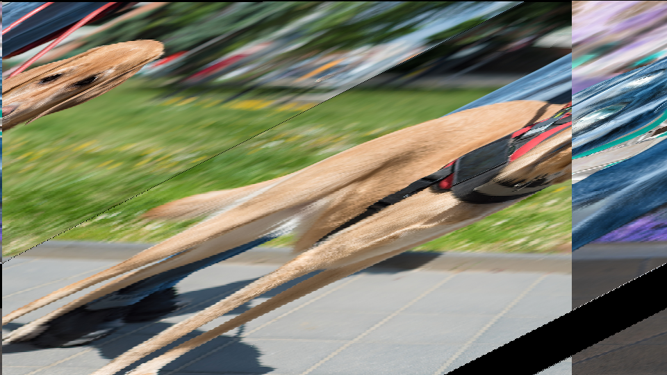
 Faultplane fracturing a video image into displaced horizontal bands, like strata of rock split along geological fault lines.
Overview
Faultplane is a mirror-displacement effect that fractures the video image into horizontal bands, shifting and reflecting them like layers of rock split along a geological fault. Two independent displacement configurations: Top and Bot: each apply their own delay offset, displacement amplitude, horizontal mirroring, and channel inversion to the video signal. A pair of timing accumulators oscillate vertically and horizontally, carving the image into a grid of displaced zones and selecting which configuration drives each zone.
At subtle settings, Faultplane produces gentle horizontal shifts and reflections that give the image a shimmering, fractured-glass quality. At extreme settings, the image shatters into a kaleidoscopic mosaic of mirrored, offset, and inverted bands that bear little resemblance to the source.
The two displacement configurations (Top and Bot) are fully independent. You can set one to a gentle mirror and the other to a wild displacement, and the timing accumulators will weave them together into a single composite texture.
What's In a Name?
In geology, a fault plane is the flat surface along which layers of rock fracture and slide past one another during an earthquake. The displaced strata on either side of the fault reveal the internal structure of the earth. Faultplane does the same thing to video: it fractures the image into bands and displaces them, revealing the internal structure of the picture in unexpected ways.
Quick Start
- Turn Vert Freq (Knob 3) to about 50%. Horizontal fault lines appear, dividing the image into alternating bands. These are the boundaries between the two displacement zones.
- Increase Top Displace (Knob 2) clockwise. One set of bands shifts horizontally, sliding the image sideways like a deck of cards fanned along a table edge.
- Now increase Bot Displace (Knob 5). The other set of bands displaces in its own direction. You now have two interleaved displacement patterns.
- Toggle Top Flip (Switch 7) to On. The Top bands mirror horizontally, creating a reflection effect within those zones.
Parameters
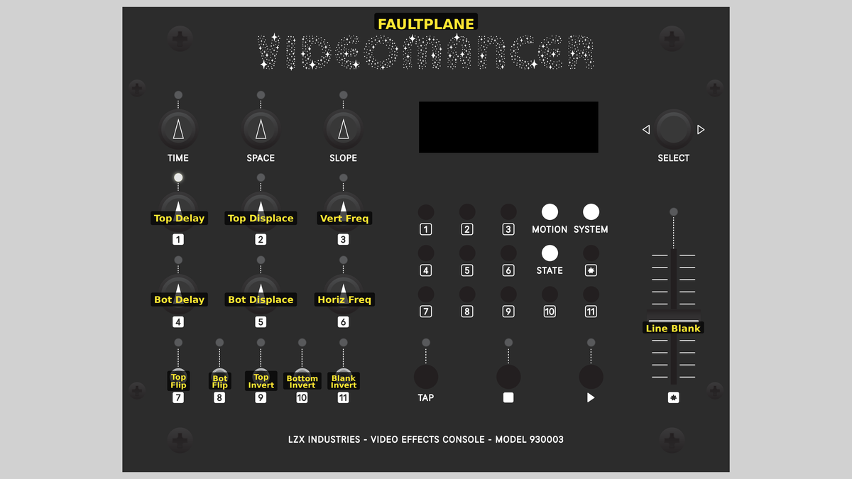 Videomancer's front panel with Faultplane active. Knobs 1–6 (top two rows of left cluster), Toggle switches 7–11 (bottom row of left cluster), Fader 12 (right side).
Knob 1 — Top Delay
| Property | Value |
|---|---|
| Range | 0.0% – 100.0% |
| Default | 0.0% |
Top Delay controls the static horizontal offset for the Top displacement zone. At 0%, fully counterclockwise, there is no offset: pixels read back from their original horizontal position. As the value increases, the readback position shifts farther along the line, sliding the image content sideways. At 100%, the maximum offset is applied. Think of Top Delay as setting the resting position of the fault: how far the displaced strata have slid.
Knob 2 — Top Displace
| Property | Value |
|---|---|
| Range | 0.0% – 100.0% |
| Default | 0.0% |
Top Displace controls the amplitude of oscillation-driven displacement for the Top zone. At 0%, the vertical timing accumulator has no effect on the Top displacement: the readback offset is determined entirely by Top Delay. As the value increases, the timing accumulator modulates the readback position with increasing amplitude, creating a rolling, wave-like displacement. At 100%, the displacement swings across the full line width.
Top Delay and Top Displace work together through a processing amplifier (proc amp). Top Delay is the DC offset and Top Displace is the gain applied to the vertical timing oscillation.
Knob 3 — Vert Freq
| Property | Value |
|---|---|
| Range | 0.0% – 100.0% |
| Default | 0.0% |
Vert Freq sets the oscillation frequency of the vertical timing accumulator. This accumulator drives the amplitude of both Top and Bot displacements, so it controls how rapidly the displacement pattern changes from line to line. At 0%, the oscillation is extremely slow, producing very wide bands. As the value increases, the bands become narrower and more numerous. At 100%, the pattern oscillates at its maximum rate, producing fine horizontal striping.
Knob 4 — Bot Delay
| Property | Value |
|---|---|
| Range | 0.0% – 100.0% |
| Default | 0.0% |
Bot Delay controls the static horizontal offset for the Bot displacement zone, in the same way that Top Delay controls the Top zone. At 0%, no offset. At 100%, maximum offset. The Bot zone alternates with the Top zone in the image, so their combined offsets create the characteristic fractured-strata appearance.
Knob 5 — Bot Displace
| Property | Value |
|---|---|
| Range | 0.0% – 100.0% |
| Default | 0.0% |
Bot Displace controls the amplitude of oscillation-driven displacement for the Bot zone. It mirrors the function of Top Displace but applies to the opposing set of horizontal bands. Setting Top Displace and Bot Displace to different values creates asymmetric displacement: one set of bands swings widely while the other remains relatively stable.
Knob 6 — Horiz Freq
| Property | Value |
|---|---|
| Range | 0.0% – 100.0% |
| Default | 0.0% |
Horiz Freq sets the oscillation frequency of the horizontal timing accumulator. This accumulator contributes to the bank selection signal (combined with the vertical accumulator) and to the blanking threshold. At 0%, the horizontal oscillation is very slow. As the value increases, vertical segmentation appears: the image is carved into columns as well as rows, creating a grid of displaced zones rather than simple horizontal bands.
Combining Vert Freq and Horiz Freq at moderate values creates a checkerboard of displacement zones: each cell in the grid independently applies either the Top or Bot configuration. This is where Faultplane becomes truly kaleidoscopic.
Switch 7 — Top Flip
| Property | Value |
|---|---|
| Off | Off |
| On | On |
| Default | Off |
Top Flip enables horizontal mirroring for the Top displacement zone. When set to Off, pixels in the Top zone are written to the line buffer in normal left-to-right order. When set to On, the write order reverses: pixels are stored right-to-left, creating a mirror image within each Top band.
Switch 8 — Bot Flip
| Property | Value |
|---|---|
| Off | Off |
| On | On |
| Default | Off |
Bot Flip enables horizontal mirroring for the Bot displacement zone. It functions identically to Top Flip but applies to the opposing set of bands. Enabling both Top Flip and Bot Flip creates a symmetric reflection pattern; enabling only one creates an asymmetric effect where alternating bands face opposite directions.
Switch 9 — Top Invert
| Property | Value |
|---|---|
| Off | Off |
| On | On |
| Default | Off |
Top Invert applies a bitwise complement to the video data before it is written to the Top displacement bank, inverting all channels (Y, U, and V) simultaneously. Luminance values flip (bright becomes dark), and chrominance values shift to their complementary hues. The inversion happens at the input stage, so the inverted data is what gets mirrored and displaced.
Switch 10 — Bottom Invert
| Property | Value |
|---|---|
| Off | Off |
| On | On |
| Default | Off |
Bottom Invert applies a bitwise complement to the video data for the Bot displacement bank. It functions identically to Top Invert but applies to the opposing bank. Enabling both creates a uniform inversion; enabling only one creates alternating bands of normal and inverted video (a striking effect that emphasizes the fracture boundaries.)
Switch 11 — Blank Invert
| Property | Value |
|---|---|
| Off | Off |
| On | On |
| Default | Off |
Blank Invert reverses the blanking logic controlled by the Line Blank fader. When set to Off, regions where both timing accumulators are below the blank threshold are blanked to black. When set to On, the logic inverts: regions above the threshold are blanked instead. This lets you toggle between showing the interior or exterior of the blanking mask.
Blank Invert has no visible effect when Line Blank (Fader 12) is at 0%, because the blank threshold is zero and no pixels are blanked in either mode.
Fader 12 — Line Blank
| Property | Value |
|---|---|
| Range | 0.0% – 100.0% |
| Default | 0.0% |
Line Blank sets a threshold for blanking portions of the output based on the timing accumulators. At 0%, no blanking occurs: the full displaced image is visible. As the value increases, zones where both accumulator values fall below the threshold are replaced with black (Y=0, U=512, V=512). At 100%, nearly the entire image is blanked. The blanking mask follows the oscillation pattern of both accumulators, carving geometric shapes out of the displaced image.
Line Blank is a powerful compositional tool. Use it with Blank Invert to isolate specific regions of the displacement pattern, creating floating fragments of fractured video against a black background.
Background
Horizontal line delay
At the heart of Faultplane is a line delay buffer: a block of memory (BRAM) that stores one full horizontal line of video. As each pixel arrives, it is written into the buffer. Simultaneously, previous pixels are read back from a different position in the buffer. When the read position differs from the write position, the output image appears shifted sideways. This is the fundamental mechanism of horizontal displacement.
Faultplane uses a dual-bank ping-pong architecture: two independent BRAM banks alternate between writing and reading on successive video lines. While bank A is writing the current line, bank B is reading back the previous line (and vice versa). This guarantees that reading and writing never collide.
Mirror and displacement
Each BRAM bank supports two transformations at the write stage:
- Mirroring: The write address can count forward (normal) or backward (reversed), flipping the stored line horizontally. This is controlled by the Top Flip and Bot Flip toggles.
- Inversion: The input data can be bitwise-complemented before storage, inverting all channels. This is controlled by the Top Invert and Bottom Invert toggles.
At the read stage, a per-bank offset shifts the readback position along the line. When the offset pushes past the end of the line, it wraps around to the beginning: creating a circular shift rather than a hard cutoff. The offset value comes from a processing amplifier that combines a static position (Delay) with a scaled oscillation (Displace).
Timing accumulators
Two timing accumulators generate periodic oscillation patterns synchronized to the video signal:
- The vertical accumulator (driven by Vert Freq) counts at the vertical rate, creating a ramp that resets once per field. Its output varies from line to line, producing horizontal banding.
- The horizontal accumulator (driven by Horiz Freq) counts at the horizontal rate, creating a ramp that resets once per line. Its output varies from pixel to pixel within each line, producing vertical segmentation.
The vertical accumulator's output feeds both proc amps, so the displacement amplitude changes from line to line: this is what creates the characteristic banded displacement pattern. The two accumulators' clock outputs are XORed to produce the bank selection signal, which determines whether each pixel receives the Top or Bot configuration.
Signal Flow
Signal Flow Notes
Two key architectural details distinguish Faultplane's signal chain:
-
Shared oscillation source: Both the Top and Bot displacement offsets are derived from the same vertical timing accumulator (accumulator A). The two proc amps apply different gain and offset to that shared ramp, producing two independent displacement curves from a single oscillation. This means the Top and Bot bands always follow the same vertical rhythm but can differ in amplitude and phase.
-
XOR bank selection: The bank selection signal is the XOR of both accumulator clocks. When only the vertical accumulator is active (Horiz Freq = 0%), the selection alternates in horizontal bands. When both accumulators are active, the selection creates a checkerboard-like grid, splitting the image into rectangular zones that alternate between Top and Bot configurations.
Order matters. Data inversion happens before the line buffer write, so inverted data is what gets mirrored and displaced. Blanking happens after the line buffer read, so it carves into the displaced result.
Exercises
These exercises progress from basic displacement to complex fractured compositions. Each exercise builds on the previous one, engaging more of the signal chain.
Exercise 1: Simple Fault Lines
 Simple Fault Lines — simulated result across source images.
Exercise Illustration
A description of the exercise illustration.
Learning Outcomes
Learn how the vertical accumulator creates horizontal displacement bands.
Key Concepts
- The vertical timing accumulator divides the image into horizontal bands
- Top Delay and Bot Delay control the static offset in each band
- The two displacement zones alternate, creating the fault-line effect
Video Source
A live camera feed or recorded footage with recognizable horizontal and vertical features (architecture, landscapes, or text).
Steps
- Create bands: Turn Vert Freq (Knob 3) to about 30%. Faint horizontal banding may appear depending on input content.
- Displace one zone: Increase Top Delay (Knob 1) to about 50%. One set of horizontal bands slides sideways. The alternating bands remain unshifted.
- Displace the other: Increase Bot Delay (Knob 4) to about 50% in the opposite direction. The two sets of bands now slide in independent directions, creating clearly visible fault lines.
- Adjust band width: Sweep Vert Freq (Knob 3) slowly. The fault lines compress and expand. Low values produce wide bands; high values produce narrow stripes.
- Mirror one zone: Toggle Top Flip (Switch 7) to On. The Top bands now show a horizontally reflected image, creating a striking contrast with the normal Bot bands.
Settings
| Control | Value |
|---|---|
| Top Delay | 50% |
| Top Displace | 0% |
| Vert Freq | 30% |
| Bot Delay | 50% |
| Bot Displace | 0% |
| Horiz Freq | 0% |
| Top Flip | On |
| Bot Flip | Off |
| Top Invert | Off |
| Bottom Invert | Off |
| Blank Invert | Off |
| Line Blank | 0% |
Exercise 2: Oscillating Displacement
 Oscillating Displacement — simulated result across source images.
Exercise Illustration
A description of the exercise illustration.
Learning Outcomes
Explore how the timing accumulators modulate displacement amplitude.
Key Concepts
- Top Displace and Bot Displace scale the vertical accumulator into the read offset
- The displacement amplitude varies from line to line, creating wave-like shifts
- Horiz Freq adds vertical segmentation for a grid pattern
Video Source
Footage with strong geometric features (tiled floors, window grids, or striped patterns.)
Steps
- Prepare: Set Vert Freq (Knob 3) to about 40% to create moderate banding.
- Oscillating Top: Increase Top Displace (Knob 2) slowly. The Top bands develop a wave-like displacement that shifts across each line. The wave amplitude grows with the knob.
- Oscillating Bot: Increase Bot Displace (Knob 5). The Bot bands develop their own wave pattern, independent of the Top.
- Asymmetric waves: Set Top Displace high (~80%) and Bot Displace low (~20%). The alternating bands now have dramatically different displacement amplitudes.
- Add horizontal segmentation: Increase Horiz Freq (Knob 6) to about 30%. The horizontal banding is now crosscut by vertical divisions, creating a grid of displaced zones.
- Inversion accent: Toggle Top Invert (Switch 9) to On. The Top zones now display inverted video, making the grid pattern even more visible.
Settings
| Control | Value |
|---|---|
| Top Delay | 0% |
| Top Displace | 80% |
| Vert Freq | 40% |
| Bot Delay | 0% |
| Bot Displace | 20% |
| Horiz Freq | 30% |
| Top Flip | Off |
| Bot Flip | Off |
| Top Invert | On |
| Bottom Invert | Off |
| Blank Invert | Off |
| Line Blank | 0% |
Exercise 3: Fractured Kaleidoscope
 Fractured Kaleidoscope — simulated result across source images.
Exercise Illustration
A description of the exercise illustration.
Learning Outcomes
Combine mirroring, inversion, displacement, and blanking for an abstract fractured composition.
Key Concepts
- Mirroring, inversion, and displacement layer together for kaleidoscopic effects
- Blanking extracts geometric shapes from the displacement pattern
- Blank Invert toggles between positive and negative mask shapes
Video Source
High-contrast footage, especially close-up textures, faces, or colorful abstract material.
Steps
- Full grid: Set Vert Freq to ~50% and Horiz Freq to ~40% to create a fine grid of displacement zones.
- Symmetric mirrors: Enable both Top Flip (Switch 7) and Bot Flip (Switch 8). The grid cells alternate between normal and mirrored images.
- Moderate displacement: Set Top Displace to ~60% and Bot Displace to ~40%. Each zone now has its own displacement wave.
- Invert one zone: Enable Top Invert (Switch 9). Alternating zones display inverted video, creating a dramatic tonal contrast across the grid.
- Carve with blanking: Increase Line Blank (Fader 12) to about 40%. Portions of the grid are replaced with black, isolating floating fragments of the pattern.
- Invert the mask: Toggle Blank Invert (Switch 11) to On. The blanking mask flips, revealing the previously hidden areas and hiding what was visible.
- Animate: Slowly sweep Top Delay (Knob 1) to shift the pattern across the blanking mask.
Settings
| Control | Value |
|---|---|
| Top Delay | 30% |
| Top Displace | 60% |
| Vert Freq | 50% |
| Bot Delay | 20% |
| Bot Displace | 40% |
| Horiz Freq | 40% |
| Top Flip | On |
| Bot Flip | On |
| Top Invert | On |
| Bottom Invert | Off |
| Blank Invert | On |
| Line Blank | 40% |
Glossary
-
Accumulator: A counter that wraps around at a configurable rate, producing a periodic ramp waveform synchronized to video timing.
-
BRAM: Block RAM; dedicated memory cells inside the FPGA used to store one or more lines of video data.
-
Displacement: Shifting the horizontal read position of a video line relative to its write position, causing the image to slide sideways.
-
Fault Plane: In geology, the surface along which rock layers fracture and slide past one another; here, the boundary between two displacement zones.
-
Line Buffer: A memory that stores exactly one horizontal line of video, enabling per-line delay and displacement effects.
-
Mirroring: Reversing the horizontal order of pixels within a line, creating a left-right reflection.
-
Ping-Pong: A dual-buffer technique where two memory banks alternate between writing and reading to avoid read-write collisions.
-
Proc Amp: Processing Amplifier; a gain-and-offset stage that scales and shifts a signal, here used to convert a timing ramp into a displacement offset.
-
Timing Accumulator: A phase accumulator synchronized to video sync signals, generating oscillation patterns at vertical or horizontal rates.
-
XOR: Exclusive OR; a logic operation that outputs true when its two inputs differ, used here to combine two oscillation clocks into a bank selection signal.