Glorious
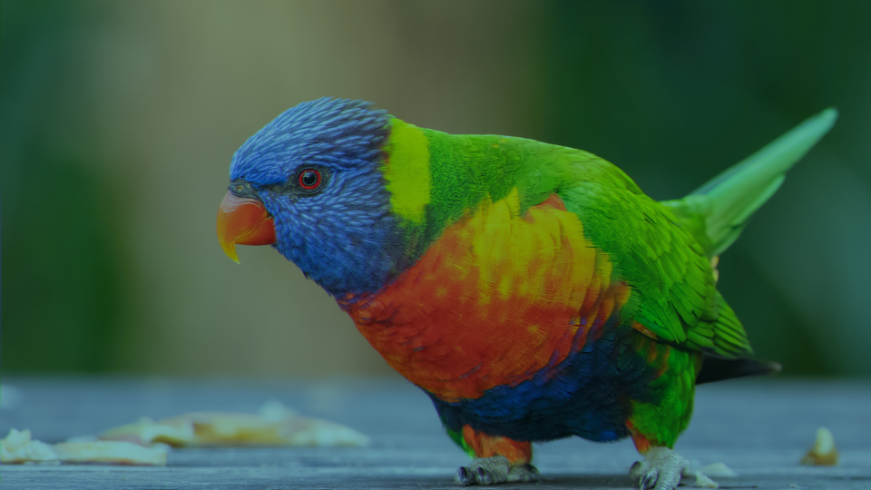
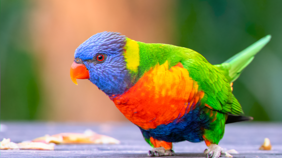 Glorious simulating three-strip Technicolor dye transfer, rendering a video source with per-channel film exposure curves and chromatic fringe.
Overview
Glorious is a three-strip Technicolor dye transfer simulation. It models the complete Technicolor Process 4 imbibition pipeline, where a camera splits light through a prism into three separate film strips: red, green, and blue: then recombines them through a dye transfer printing process. The result is the saturated, slightly imperfect color palette that defined Hollywood's golden age.
Glorious works by converting the input YUV video into RGB, applying independent film response curves to each color channel, introducing controllable registration misalignment between the dye layers, blending inter-channel contamination, and re-encoding back to YUV. The pipeline recreates not just the color science of Technicolor, but its physical imperfections: the fringe halos where strips don't align, the dye bleed where one layer contaminates another, and the way shadows compress and highlights roll off according to the Hurter–Driffield (H&D) density curve of photographic film.
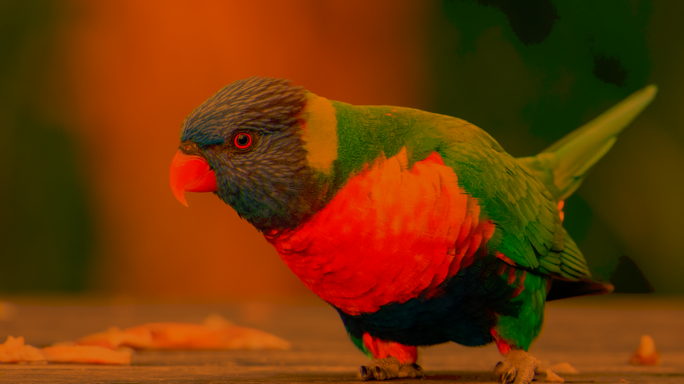
At gentle settings, Glorious adds a warm filmic color shift. At extreme settings, it produces aggressive color separation, chromatic halos, and faded vintage looks.
What's In a Name?
The name Glorious is borrowed from the term Glorious Technicolor, the marketing tagline used in classic Hollywood film titles. It's a celebration of the era when color itself was the spectacle: when audiences gasped at ruby reds and emerald greens that seemed impossibly vivid compared to the black-and-white films they replaced.
Quick Start
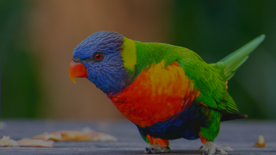
- Feed a colorful video source into Videomancer. Leave all controls at their defaults. The image already has a subtle Technicolor shift from the H&D curve and default saturation boost.
- Turn Red Exp (Knob 1) counterclockwise and Blue Exp (Knob 2) clockwise. The color balance tips: reds darken while blues brighten, simulating unequal printer light exposure across the film strips.
- Increase Fringe (Knob 4) to step 4 or higher. Chromatic halos appear at high-contrast edges where the red and blue strips separate from the green reference.
- Increase Matrix Bleed (Knob 6) to about 50%. Colors begin to contaminate each other, producing the warm, slightly impure palette characteristic of dye transfer prints.
Parameters
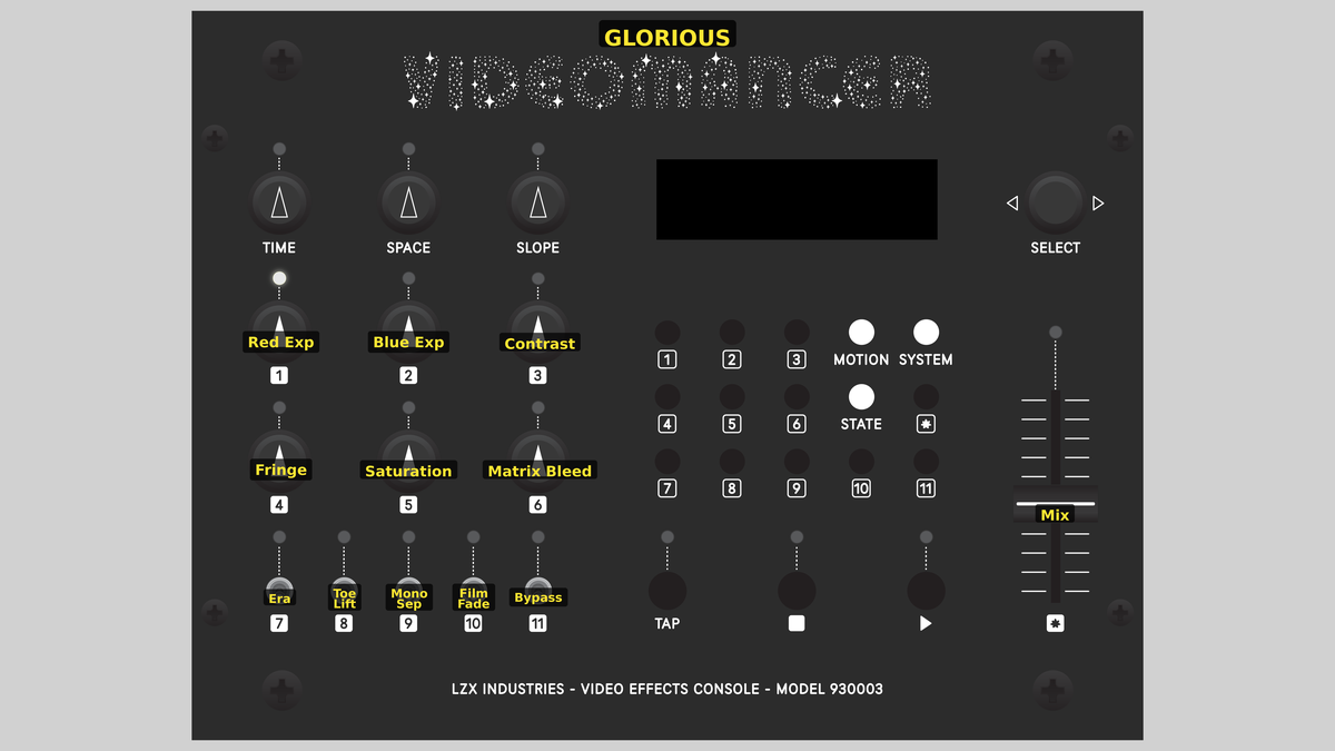 Videomancer's front panel with Glorious active. Knobs 1–6 (top two rows of left cluster), Toggle switches 7–11 (bottom row of left cluster), Fader 12 (right side).
Knob 1 — Red Exp
| Property | Value |
|---|---|
| Range | 0.0% – 200.0% |
| Default | 100.1% |
Red Exp controls the exposure of the red film strip, simulating the printer light intensity used when exposing the red separation negative. At 0%, the red channel is nearly black: no light reaches the red strip. At the default 100%, the red strip receives nominal exposure. Increasing beyond 100% overexposes the red channel, brightening reds and warming the overall image.
The green channel's exposure is automatically derived as the average of Red Exp and Blue Exp, keeping the green record centered between the two outer strips.
In real Technicolor printing, the lab technician adjusted each printer light independently to balance color across scenes. Manipulating Red Exp and Blue Exp together simulates that process.
Knob 2 — Blue Exp
| Property | Value |
|---|---|
| Range | 0.0% – 200.0% |
| Default | 100.1% |
Blue Exp controls the exposure of the blue film strip. At 0%, blues are suppressed. At 100% (default), the blue strip receives nominal exposure. Above 100%, blues are overexposed, cooling the image and intensifying sky tones. As with Red Exp, the green channel tracks the average of the two outer channels.
Knob 3 — Contrast
| Property | Value |
|---|---|
| Range | 0.0% – 100.0% |
| Default | 50.0% |
Contrast adjusts the steepness of the H&D film response curve applied to all three channels. At 0%, the curve has a very short straight section: shadows and highlights compress heavily, producing a soft, flat image. At 100%, the straight section extends across nearly the full range, producing a contrasty, punchy result with minimal toe and shoulder compression.
The H&D curve is a piecewise S-curve: the toe compresses shadows (half gain), the straight section passes values unchanged, and the shoulder compresses highlights (one-eighth gain). Contrast controls how much of the input range falls into the straight section.
Knob 4 — Fringe
| Property | Value |
|---|---|
| Range | 0 – 7 |
| Default | 1 |
Fringe controls the dye registration misalignment between the red, green, and blue strips. At step 0, all three channels are perfectly aligned. Each step shifts the red strip forward and the blue strip backward by one pixel relative to the green reference channel, using a shift register delay. At step 7, the maximum offset produces dramatic chromatic halos at every high-contrast edge.
In the real process, mechanical tolerances in the dye transfer press caused slight misregistration between the three strips, producing colored fringe at object boundaries.
Knob 5 — Saturation
| Property | Value |
|---|---|
| Range | 0.0% – 200.0% |
| Default | 150.1% |
Saturation boosts or cuts the color intensity of the re-encoded YUV output. At 0%, the image is nearly desaturated. At the default 150% (knob at 75%), colors are boosted above unity to simulate the heightened dye density of a Technicolor print. At 200%, colors are extremely vivid and may clip.
Knob 6 — Matrix Bleed
| Property | Value |
|---|---|
| Range | 0.0% – 100.0% |
| Default | 12.5% |
Matrix Bleed introduces inter-channel dye contamination. In real dye transfer printing, each strip's dye would slightly stain the adjacent layers during imbibition. At 0%, the channels are clean. As Matrix Bleed increases, each channel receives a portion of its neighbors: red gets green and blue, green gets red and blue, and blue gets green and red. At 100%, the contamination is heavy, producing a warm, murky palette with reduced color purity.
The bleed matrix is asymmetric by design. Each channel receives its immediate neighbor at full bleed strength and its opposite channel at half strength, mimicking the physical proximity of dye layers in the imbibition stack.
Switch 7 — Era
| Property | Value |
|---|---|
| Off | 3-Strip |
| On | 1-Strip |
| Default | 3-Strip |
Era selects between two Technicolor epochs. In the 3-Strip position, the full fringe offset from Fringe (Knob 4) is applied. In the 1-Strip position, the fringe is halved, simulating the improved registration accuracy of later single-strip Eastmancolor processes that succeeded three-strip Technicolor.
Switch 8 — Toe Lift
| Property | Value |
|---|---|
| Off | Crushed |
| On | Lifted |
| Default | Crushed |
Toe Lift controls the behavior of the shadow region in the H&D curve. In the Crushed position, the toe compresses shadows all the way to black. In the Lifted position, a fixed offset raises the darkest values, preventing pure black and simulating the slightly fogged base density of aged or low-contrast film stock.
Switch 9 — Mono Sep
| Property | Value |
|---|---|
| Off | Color |
| On | Mono |
| Default | Color |
Mono Sep selects between full-color output and a single-channel green record separation. In the Color position, the complete three-strip RGB-to-YUV re-encode runs normally. In the Mono position, only the green channel is used as luminance and the chrominance is zeroed, producing a monochrome image that shows the green separation record: the strip that carried the most luminance detail in the original Technicolor process.
Switch 10 — Film Fade
| Property | Value |
|---|---|
| Off | Fresh |
| On | Aged |
| Default | Fresh |
Film Fade simulates the aging of a Technicolor print. In the Fresh position, all three dye layers retain full density. In the Aged position, the red channel is attenuated by half, mimicking the characteristic magenta fade that occurs as the cyan dye layer in vintage prints degrades faster than the other dyes, shifting the image toward cyan-green tones.
Switch 11 — Negative
| Property | Value |
|---|---|
| Off | Off |
| On | On |
| Default | Off |
Negative inverts the processed signal before the dry/wet mix. In the Off position, the output is a positive image. In the On position, each channel is complemented (1023 minus value), producing a film negative look. Because the inversion is applied after all processing but before the mix, the dry signal path remains unaffected.
Negative is not a bypass toggle. It inverts the processed (wet) signal only. The Mix fader blends between the original dry input and the inverted wet signal.
Fader 12 — Mix
| Property | Value |
|---|---|
| Range | 0.0% – 100.0% |
| Default | 100.0% |
Mix crossfades between the original dry input and the processed wet signal. At 0%, the output is the unprocessed input. At 100% (default), the output is fully processed. Intermediate values blend the two, useful for dialing in subtle Technicolor tinting over the original footage.
Background
Three-Strip Technicolor
Technicolor Process 4, introduced in 1932, used a beam-splitting prism inside the camera to expose three separate black-and-white film strips through red, green, and blue filters simultaneously. After development, each strip became a separation negative capturing one-third of the visible spectrum. Positive prints were made by transferring precise amounts of cyan, magenta, and yellow dye from gelatin matrices: one per strip: onto a single blank film in a process called imbibition. The result was exceptionally saturated, stable color with a distinctive palette that digital color grading still tries to emulate.
The H&D Curve
Every photographic emulsion has a characteristic response to light, described by the Hurter–Driffield curve (also called the D-log-E curve). The curve has three regions: the toe (shadows, where response is compressed), the straight section (midtones, where response is roughly linear), and the shoulder (highlights, where the film density saturates). Glorious implements this as a piecewise function: half gain in the toe, unity in the straight section, and one-eighth gain in the shoulder. The Contrast parameter controls how much of the input range falls into the straight section.
Dye Misregistration
Because Technicolor's three dye layers were physically stacked during imbibition, even slight mechanical misalignment produced colored fringe at high-contrast boundaries. A dark edge against a bright background would show thin halos of red on one side and blue on the other, with the green layer as the reference. Glorious recreates this with a pair of shift register delay lines: one for red, one for blue: that offset each channel by a configurable number of pixels relative to the green record.
Signal Flow
Signal Flow Notes
The pipeline decomposes input YUV into RGB for per-channel film simulation, then re-encodes back to YUV for output. This round-trip is essential because the Technicolor process operates on separated color channels, not luminance and chrominance.
Two key interactions shape the result. First, the green channel exposure is always the average of red and blue exposure: you can't control it independently. This mirrors the role of the green record as the principal luminance carrier in Technicolor: it was always printed at a calibrated exposure relative to the other two strips. Second, fringe is applied after the H&D curve, meaning the nonlinear film response shapes the color values before the shift registers introduce misalignment. The halos inherit the compressed tonal response, which is why they appear soft and filmic rather than harsh.
Film Fade is applied during the matrix bleed stage: it halves the red channel after contamination. This means bleed from red into green and blue is calculated at full strength, but the red channel itself fades. The result is a warm cyan-green shift that matches real aged-print behavior.
Exercises
These exercises progress from basic exposure balance through full vintage film degradation. Each builds on the previous, engaging more of the processing pipeline.
Exercise 1: Printer Light Balancing
 Printer Light Balancing — simulated result across source images.
Exercise Illustration
A description of the exercise illustration.
Learning Outcomes
Learn how per-channel exposure controls shape the Technicolor color palette.
Key Concepts
- Each knob controls one film strip's printer light intensity
- Green exposure is automatically derived from the average of red and blue
- The H&D curve shapes all three channels identically by default
Video Source
A colorful, well-lit scene with recognizable warm and cool tones (a face with a blue sky, or fruit on a table.)
Steps
- Default warmth: Leave all controls at defaults. Observe the subtle warm shift from the default H&D curve and saturation boost.
- Kill the reds: Turn Red Exp (Knob 1) fully counterclockwise. Reds vanish, leaving a cool cyan-blue image.
- Kill the blues: Return Red Exp to center, then turn Blue Exp (Knob 2) fully counterclockwise. Blues vanish, leaving a warm orange-red image.
- Balanced underexposure: Set both Red Exp and Blue Exp to about 75%. Notice how the balanced underexposure darkens the image and compresses tones through the H&D toe.
- Restore punch: Increase Contrast (Knob 3) to about 80%. The straight section of the H&D curve extends, restoring punch to the underexposed image.
Settings
| Control | Value |
|---|---|
| Red Exp | 75.0% |
| Blue Exp | 75.0% |
| Contrast | 80.0% |
| Fringe | 0 |
| Saturation | 150.0% |
| Matrix Bleed | 25.0% |
| Era | 3-Strip |
| Toe Lift | Crushed |
| Mono Sep | Color |
| Film Fade | Fresh |
| Negative | Off |
| Mix | 100.0% |
Exercise 2: Chromatic Fringe and Bleed
 Chromatic Fringe and Bleed — simulated result across source images.
Exercise Illustration
A description of the exercise illustration.
Learning Outcomes
Explore dye registration misalignment and inter-channel contamination.
Key Concepts
- Fringe shifts red and blue channels in opposite directions relative to green
- Matrix bleed simulates dye contamination between adjacent strips
- The Era toggle halves fringe for single-strip mode
Video Source
High-contrast footage with strong edges: text on a white background, silhouettes, or architectural details.
Steps
- Introduce fringe: Set Fringe (Knob 4) to step 4. Chromatic halos appear at every strong edge: red on one side, blue on the other.
- Halve the offset: Toggle Era (Switch 7) to 1-Strip. The fringe halves, producing subtler halos.
- Add dye bleed: Return Era to 3-Strip. Increase Matrix Bleed (Knob 6) to about 60%. Colors blur into each other as dye contamination increases.
- Maximum separation: Set Fringe to step 7. The maximum offset produces wide, painterly color separation.
- Green record only: Enable Mono Sep (Switch 9) to Mono. The image collapses to a monochrome green separation record, but the fringe is still visible as brightness shifts.
Settings
| Control | Value |
|---|---|
| Red Exp | 100.0% |
| Blue Exp | 100.0% |
| Contrast | 50.0% |
| Fringe | 4 |
| Saturation | 150.0% |
| Matrix Bleed | 60.0% |
| Era | 3-Strip |
| Toe Lift | Crushed |
| Mono Sep | Color |
| Film Fade | Fresh |
| Negative | Off |
| Mix | 100.0% |
Exercise 3: Aged Vintage Print
 Aged Vintage Print — simulated result across source images.
Exercise Illustration
A description of the exercise illustration.
Learning Outcomes
Combine film fade, toe lift, and saturation to create a degraded vintage print look.
Key Concepts
- Film Fade simulates magenta dye loss by halving the red channel
- Toe Lift raises shadow density, preventing pure black
- Negative inverts the wet signal before the mix crossfade
Video Source
Any footage with a mix of shadows and highlights: a sunset, a dimly lit room, or a performer under stage lights.
Steps
- Fade the dyes: Enable Film Fade (Switch 10) to Aged. The image shifts toward cyan-green as the red channel fades, simulating a decades-old print.
- Lift the shadows: Enable Toe Lift (Switch 8) to Lifted. Shadows rise slightly: the deepest blacks become a foggy dark gray, like a print with base density fog.
- Flatten the curve: Reduce Contrast (Knob 3) to about 30%. The H&D curve flattens, compressing the tonal range into a soft, low-contrast image.
- Muddy the colors: Increase Matrix Bleed (Knob 6) to about 40%. The faded dyes bleed into each other, further muddying the color purity.
- Registration slip: Add moderate Fringe (Knob 4) at step 2–3. The slight misregistration completes the degraded vintage look.
- Cross-process blend: Toggle Negative (Switch 11) to On and adjust Mix (Fader 12) to about 60%. The blended negative creates an ethereal, cross-processed film effect.
Settings
| Control | Value |
|---|---|
| Red Exp | 90.0% |
| Blue Exp | 90.0% |
| Contrast | 30.0% |
| Fringe | 3 |
| Saturation | 115.0% |
| Matrix Bleed | 40.0% |
| Era | 3-Strip |
| Toe Lift | Lifted |
| Mono Sep | Color |
| Film Fade | Aged |
| Negative | On |
| Mix | 60.0% |
Glossary
-
Beam Splitter: An optical prism inside a Technicolor camera that divides incoming light into three separate paths, each filtered to record one color channel on its own film strip.
-
Dye Transfer: A printing process in which dye from gelatin matrices is absorbed into a blank film through contact, producing the final color image.
-
Fringe: Colored halos at high-contrast edges caused by misalignment between the red, green, and blue dye layers during printing.
-
H&D Curve: The Hurter–Driffield curve describing a photographic emulsion's density response to light exposure, with toe, straight section, and shoulder regions.
-
Imbibition: The physical process of transferring dye from a gelatin relief matrix to a receiving film by soaking, used in Technicolor Process 4.
-
Matrix Bleed: Inter-channel dye contamination where one color layer stains adjacent layers during the imbibition process.
-
Printer Light: The intensity of illumination used when exposing a film strip through a separation negative, controlling the density of each color channel.
-
Separation Negative: A black-and-white film strip recording a single color channel (red, green, or blue), created by filming through a color filter.
-
Shoulder: The upper region of the H&D curve where film density saturates and additional exposure produces diminishing returns in density.
-
Three-Strip: The Technicolor process using three separate film strips, each recording one color through a beam-splitting prism.
-
Toe: The lower region of the H&D curve where film response is compressed, producing soft, low-contrast shadow detail.
-
Toe Lift: A fixed offset added to the toe region of the H&D curve that prevents pure black, simulating base fog density in aged film stock.