Scramble
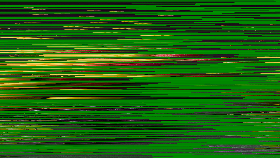 Scramble applying per-line cut-and-rotate shuffling with periodic video inversion and sync jitter to simulate a failing analog TV descrambler.
Overview
Scramble recreates the look of an analog TV signal that has been scrambled for pay-per-view and then improperly decoded by a faulty or unauthorized descrambler box. Each scanline of the video is sliced at a different point and rotated, producing the instantly recognizable "shuffled blinds" effect of systems like VideoCrypt and Nagravision. Additional artifacts: periodic video inversion, horizontal jitter, and drifting decode lock: complete the illusion of intercepted cable television.
The magic is in the Decode control. As you turn it, the scrambled image drifts toward intelligibility, occasionally snapping into brief, tantalizing clarity before losing lock and collapsing back into chaos. This imperfect decoding is the signature aesthetic: the viewer knows something is there, almost visible, but just out of reach.
Scramble is an artifact simulator, not a signal degrader. It doesn't reduce resolution or destroy information: it rearranges it. Every pixel is still present; they've just been shuffled. That's why the Decode knob can bring the image back.
What's In a Name?
The name Scramble is a direct reference to analog television scrambling: the practice of deliberately disrupting a broadcast signal so that only paying subscribers with authorized descramblers could watch. The word captures both the technical process (scrambling pixel positions) and the frantic urgency of trying to decode a signal you're not supposed to see.
Quick Start
- Turn Cut Depth (Knob 1) clockwise to about 50%. The image shatters into horizontal strips, each shifted sideways by a different amount (a classic scrambled channel.)
- Slowly sweep Decode (Knob 2) from left to right. The strips realign. There's a sweet spot where the image snaps briefly into focus, then drifts apart again.
- Turn Invert Period (Knob 4) up to step 3 or 4. Groups of scanlines periodically flip to negative, adding the characteristic black-and-white banding of a failing descrambler.
- Increase Jitter (Knob 5) to about 25%. Each scanline now wobbles horizontally, simulating sync-suppression artifacts that make the image shimmer and tear.
Parameters
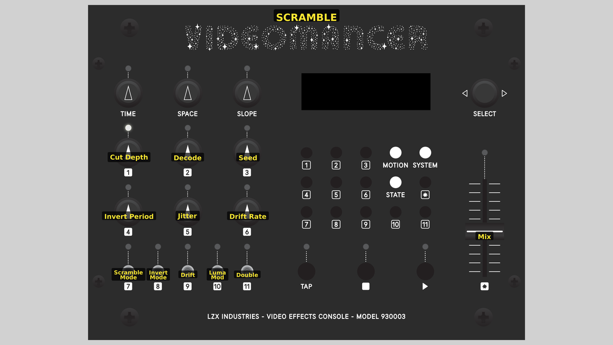 Videomancer's front panel with Scramble active. Knobs 1–6 (top two rows of left cluster), Toggle switches 7–11 (bottom row of left cluster), Fader 12 (right side).
Knob 1 — Cut Depth
| Property | Value |
|---|---|
| Range | 0.0% – 100.0% |
| Default | 50.0% |
Cut Depth controls the maximum horizontal displacement applied to each scanline during the cut-and-rotate shuffle. At 0%, fully counterclockwise, no displacement occurs and the image passes through unscrambled. As the value increases, the cut points stretch further across the scanline, producing more dramatic horizontal offsets. At 100%, fully clockwise, each line can be rotated by up to the full width of the active picture. The resulting image looks like a stack of horizontal strips that have been slid sideways by varying amounts.
Knob 2 — Decode
| Property | Value |
|---|---|
| Range | 0.0% – 100.0% |
| Default | 0.0% |
Decode is the descrambler alignment offset. It subtracts from the per-line cut point, attempting to undo the scrambling and restore the original image. When Decode exactly cancels the LFSR-generated offset for a given line, that line snaps back into its correct position. At 0%, no correction is applied. As you increase the value, more lines realign. The sweet spot where the entire image becomes momentarily coherent depends on the Seed and Cut Depth settings.
Think of Decode as a pirate descrambler's tuning knob. Finding the right setting is a game of cat and mouse: the image locks briefly, then slides away as the LFSR sequence drifts past.
Knob 3 — Seed
| Property | Value |
|---|---|
| Range | 0.0% – 100.0% |
| Default | 25.0% |
Seed sets the initial value of the 16-bit linear feedback shift register (LFSR) that generates the per-line cut points. Different seeds produce different scrambling patterns. At the start of each frame, the LFSR is reloaded with the seed value (combined with the current drift offset), ensuring a repeatable pattern. Changing the seed rotates through entirely different arrangements of line offsets, each producing a distinct scrambled texture.
Knob 4 — Invert Period
| Property | Value |
|---|---|
| Range | 0 – 7 |
| Default | 0 |
Invert Period selects which bit of the line counter controls periodic video inversion. The control is quantized to 8 steps (0 to 7). At step 0, inversion is disabled. Steps 1 through 7 select progressively higher bits of the vertical line counter, creating inversion zones that alternate every 2, 4, 8, 16, 32, 64, or 128 lines respectively. Higher steps produce wider bands of inverted video.
Inversion simulates the sync suppression technique used by analog scramblers, where alternating portions of the signal had their polarity reversed to confuse unauthorized decoders.
Knob 5 — Jitter
| Property | Value |
|---|---|
| Range | 0.0% – 100.0% |
| Default | 12.5% |
Jitter controls the amplitude of per-line horizontal displacement noise. A 10-bit LFSR generates a random offset each scanline, scaled by this control. At 0%, no jitter is applied. Increasing the value adds progressively wilder horizontal wobble to each line. At extreme settings, individual scanlines slide far enough sideways to wrap around the picture, creating a shimmering, tearing distortion reminiscent of a TV with damaged horizontal sync.
Knob 6 — Drift Rate
| Property | Value |
|---|---|
| Range | 0.0% – 100.0% |
| Default | 0.0% |
Drift Rate controls how quickly the internal decode alignment changes over time. When Drift (Switch 9) is enabled, an accumulator adds the drift rate value each frame, slowly rotating through different seed offsets. At 0%, the drift is frozen even when enabled. Higher values cause the descrambler lock to cycle faster, producing a rhythmic pattern of decoding and re-scrambling.
Switch 7 — Scramble Mode
| Property | Value |
|---|---|
| Off | LFSR |
| On | Sawtooth |
| Default | LFSR |
Scramble Mode selects the source of per-line cut-point offsets. In LFSR mode, a pseudo-random sequence produces the classic scrambled-channel look where each line is displaced by a seemingly random amount. In Sawtooth mode, the line counter itself is used as the offset source, creating a smooth diagonal shear across the image: as if the picture were printed on a cylinder and sliced on an angle.
Switch 8 — Invert Mode
| Property | Value |
|---|---|
| Off | Luma |
| On | Full YUV |
| Default | Luma |
Invert Mode determines which channels are affected by periodic video inversion. In Luma mode, only the Y (brightness) channel is inverted, producing alternating bands of positive and negative luminance while colors remain stable. In Full YUV mode, both luminance and chrominance are inverted, creating complementary color banding: blues become oranges, greens become magentas: for a more aggressive, psychedelic distortion.
Switch 9 — Drift
| Property | Value |
|---|---|
| Off | Off |
| On | On |
| Default | Off |
Drift enables or disables the auto-drift accumulator. When Off, the scramble pattern is static from frame to frame (assuming constant Seed and Decode values). When On, the internal offset evolves each frame at the rate set by Drift Rate (Knob 6), causing the image to cycle between scrambled and momentarily decoded states: the lock-and-lose animation of a descrambler slowly falling out of sync.
Switch 10 — Luma Mod
| Property | Value |
|---|---|
| Off | Off |
| On | On |
| Default | Off |
Luma Mod enables luminance-reactive modulation of the cut point. When Off, cut displacement is determined solely by the LFSR (or sawtooth) and the Decode offset. When On, the brightness of each input pixel is added to the read address, causing brighter areas to displace further. The result is content-dependent scrambling where the shuffling pattern follows the tonal contours of the source image.
Luma Mod dramatically increases visual complexity. Combine it with high Cut Depth for extreme image disintegration where the scrambling pattern mirrors the source content.
Switch 11 — Double
| Property | Value |
|---|---|
| Off | Off |
| On | On |
| Default | Off |
Double enables double-scramble mode. When Off, each scanline receives a single cut-and-rotate operation. When On, a second displacement is generated by XORing two halves of the LFSR register, and this additional offset is applied on top of the first. The result is a more aggressively disrupted image that is harder to decode, as if the signal passed through two separate scrambling stages.
Fader 12 — Mix
| Property | Value |
|---|---|
| Range | 0.0% – 100.0% |
| Default | 100.0% |
Mix crossfades between the original (dry) input and the processed (wet) scrambled output. At 0%, only the dry signal is heard: the image is untouched. At 100%, only the scrambled result is visible. Intermediate values blend the two, creating a ghostly overlay of the original image beneath the scrambled version.
Background
Analog TV scrambling
In the analog television era, premium channels protected their signals using line-shuffle scrambling systems like VideoCrypt (used by Sky Television in Europe) and Nagravision (used by Canal+ in France). These systems worked by cutting each scanline at a pseudo-random point and swapping the two halves. The cut point changed every line, determined by a sequence known only to authorized smart cards. Without the correct decryption key, the viewer saw a chaotic mosaic of horizontally displaced strips (recognizable as television but completely unwatchable.)
The infamous "descrambler box" was an unauthorized decoder that attempted to guess or crack the cut-point sequence. When it got close, the image would flash into partial clarity before dissolving again. Scramble recreates this entire experience in FPGA hardware.
Line-buffer cut-and-rotate
The core technique is deceptively simple. Each scanline is written pixel-by-pixel into a line buffer: a block of RAM that holds one full row of video. On readback, the address is offset by the per-line cut point, effectively rotating the line contents. Because the read address wraps around the buffer, no pixels are lost; they simply appear at different horizontal positions. The result is a circular shift of each scanline by a different amount.
The cut point comes from one of two sources: a 16-bit LFSR that produces pseudo-random values, or a sawtooth ramp derived from the line counter. The LFSR produces the classic scrambled look; the sawtooth creates a smooth diagonal displacement.
Sync suppression and jitter
Real analog scramblers didn't just shuffle pixels: they also attacked the synchronization signals that keep a television's scanning circuits locked. Sync suppression reduced or inverted the sync pulses, causing the TV's horizontal oscillator to drift. Scramble simulates this with two mechanisms: periodic video inversion (alternating groups of lines are negated) and horizontal jitter (each line is nudged sideways by a random amount). Together, these artifacts complete the illusion of a signal that refuses to be tamed.
Signal Flow
Signal Flow Notes
The processing pipeline is dominated by the line buffer and its address computation. Each scanline is written sequentially into BRAM. On readback, six offsets are combined to form the read address: the LFSR or sawtooth cut point (scaled by Cut Depth), the Decode subtraction, the Drift accumulator, optional Luma Mod, optional Double scramble, and Jitter noise. All six additions and subtractions happen in unsigned arithmetic and naturally wrap around the buffer.
The Decode knob works by subtraction. When Decode exactly equals the LFSR cut point for a given line, the read offset becomes zero and that line appears in its correct position. This is why sweeping Decode produces a "tuning" sensation (different lines lock in at different Decode values.)
Out-of-range detection compares the computed read address against the actual line width. When displacement pushes the read beyond the written region, the output is forced to black (Y=0) with neutral chroma (U=512, V=512), preventing stale BRAM data from appearing as green artifacts.
Exercises
These exercises progress from basic scrambling to the full descrambler simulation. Each one introduces additional layers of the analog scrambling aesthetic.
Exercise 1: Classic Scrambled Channel
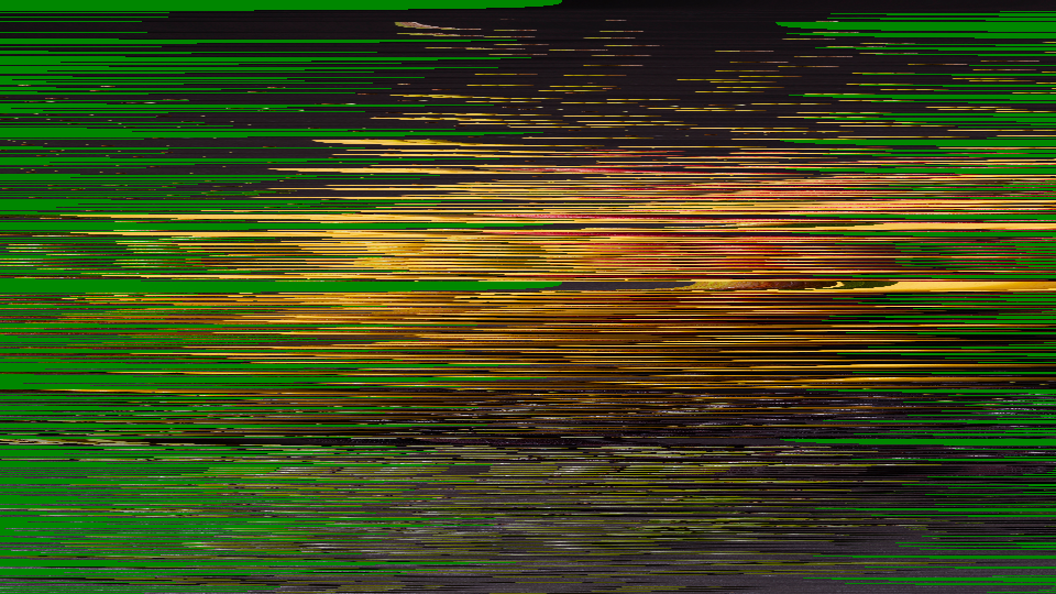 Classic Scrambled Channel — simulated result across source images.
Exercise Illustration
A description of the exercise illustration.
Learning Outcomes
Reproduce the look of a scrambled pay-per-view channel using cut-and-rotate line shuffling.
Key Concepts
- Line-buffer cut-and-rotate is a circular shift per scanline
- The LFSR produces pseudo-random cut points
- Cut Depth scales the displacement amplitude
Video Source
A live camera feed or recorded footage with clear horizontal features (text, faces, architectural lines).
Steps
- Break the image: Set Cut Depth (Knob 1) to about 70%. The image breaks into horizontally displaced strips.
- Full scramble: Leave Decode (Knob 2) at 0%. This is the fully scrambled state.
- Chase the lock: Slowly sweep Decode from 0% to 100%. Strips begin to realign (some lines lock into place briefly before sliding away.)
- Change the pattern: Set Seed (Knob 3) to different values. Notice how the scramble pattern changes entirely with each seed.
- Smooth shear: Toggle Scramble Mode (Switch 7) to Sawtooth. The random displacement becomes a smooth diagonal shear.
Settings
| Control | Value |
|---|---|
| Cut Depth | ~70% |
| Decode | 0% |
| Seed | ~25% |
| Invert Period | 0 |
| Jitter | 0% |
| Drift Rate | 0% |
| Scramble Mode | LFSR |
| Invert Mode | Luma |
| Drift | Off |
| Luma Mod | Off |
| Double | Off |
| Mix | 100% |
Exercise 2: Descrambler Lock and Drift
 Descrambler Lock and Drift — simulated result across source images.
Exercise Illustration
A description of the exercise illustration.
Learning Outcomes
Simulate the experience of a descrambler box drifting in and out of sync with the encrypted signal.
Key Concepts
- The Drift accumulator cycles the seed offset over time
- Different Drift Rate values produce different lock/unlock rhythms
- Decode and Drift interact to create a tuning window
Video Source
Footage with strong contrast and recognizable subjects: the effect is most dramatic when you can tell whether the image is "locked" or not.
Steps
- Partial decode: Set Cut Depth (Knob 1) to 50% and Decode (Knob 2) to about 40%.
- Enable drift: Enable Drift (Switch 9) and set Drift Rate (Knob 6) to about 20%. The image slowly cycles between scrambled and partially decoded states.
- Add inversion bands: Add Invert Period (Knob 4) at step 3. Bands of inverted video appear and disappear as the drift cycles.
- Wobble the lines: Increase Jitter (Knob 5) to about 15%. The horizontal wobble adds urgency to the decoding struggle.
- Chase the sync: Slowly adjust Decode while Drift is running. Notice how you can "chase" the lock point: the image stabilizes briefly when Decode aligns with the current drift state.
Settings
| Control | Value |
|---|---|
| Cut Depth | 50% |
| Decode | ~40% |
| Seed | ~25% |
| Invert Period | 3 |
| Jitter | ~15% |
| Drift Rate | ~20% |
| Scramble Mode | LFSR |
| Invert Mode | Luma |
| Drift | On |
| Luma Mod | Off |
| Double | Off |
| Mix | 100% |
Exercise 3: Full Signal Chaos
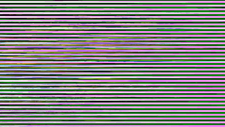
 Full Signal Chaos — simulated result across source images.
Exercise Illustration
A description of the exercise illustration.
Learning Outcomes
Push all disruption layers simultaneously for maximum analog interference texture.
Key Concepts
- Double scramble adds a second displacement layer
- Luma Mod makes the scrambling content-dependent
- Full YUV inversion creates complementary color banding
Video Source
High-contrast footage or graphic patterns: bold shapes survive the extreme processing and remain partially recognizable.
Steps
- Maximum displacement: Set Cut Depth (Knob 1) to 80% and Decode (Knob 2) to 0%.
- Double scramble: Enable Double (Switch 11). The scrambling becomes more aggressive and harder to decode.
- Content-aware chaos: Enable Luma Mod (Switch 10). Bright areas now displace further, making the scramble pattern follow the content.
- Color inversion bands: Set Invert Period (Knob 4) to step 2 and switch Invert Mode (Switch 8) to Full YUV. Alternating bands of complementary colors appear.
- Wild jitter: Increase Jitter (Knob 5) to 50%. Each scanline now wobbles wildly.
- Animated texture: Enable Drift (Switch 9) with Drift Rate (Knob 6) at 40%. The entire texture animates continuously.
- Blend with original: Sweep Mix (Fader 12) to blend the chaotic output with the clean original.
Settings
| Control | Value |
|---|---|
| Cut Depth | 80% |
| Decode | 0% |
| Seed | ~50% |
| Invert Period | 2 |
| Jitter | 50% |
| Drift Rate | 40% |
| Scramble Mode | LFSR |
| Invert Mode | Full YUV |
| Drift | On |
| Luma Mod | On |
| Double | On |
| Mix | 100% |
Glossary
-
Cut-and-Rotate: A scrambling technique that slices a scanline at a pseudo-random point and swaps the two halves, circularly shifting the pixel data.
-
Descrambler: A device that attempts to reverse a scrambling process by predicting or computing the correct cut-point sequence for each line.
-
Drift: A gradual shift in the decoder's alignment with the scrambled signal, causing periodic cycles of locking and losing the decoded image.
-
Jitter: Small, rapid, random displacements of scanlines in the horizontal direction, simulating sync-suppression interference.
-
LFSR: Linear Feedback Shift Register; a shift register whose input bit is a function of its previous state, producing a pseudo-random binary sequence.
-
Line Buffer: A block of RAM that stores one complete scanline of video, enabling random-access readback at offset addresses.
-
Luma Modulation: Using the brightness value of each pixel to influence a processing parameter, creating content-dependent effects.
-
Sawtooth: A waveform that ramps linearly then resets, used here as an alternative to LFSR for generating a smooth diagonal shear pattern.
-
Scrambling: The deliberate disruption of a video signal to prevent unauthorized viewing, typically by rearranging pixel positions or inverting signal polarity.
-
Sync Suppression: An analog scrambling technique that reduces or inverts synchronization pulses, causing the receiver's scanning circuits to lose lock.
-
VideoCrypt: A line-shuffle scrambling system used by Sky Television in Europe, which cut and rotated each scanline at a smart-card-determined point.