Modulation Guide
Overview
Every FPGA program on Videomancer exposes up to twelve parameters — six rotary knobs, five toggle switches, and one fader. In normal operation, those parameters sit wherever you leave them. The modulation engine changes that. It writes new values to those parameters automatically, every video field, so the controls move on their own.
Twelve modulator channels (P1 through P12) map one-to-one onto the twelve physical controls. Each channel runs an independent operator — a small signal-processing algorithm that produces a continuous stream of values spanning the full modulation range. That stream replaces (or combines with) the manual knob position, causing the FPGA program's behavior to change over time without you touching anything.
There are 39 operator types. Some are simple oscillators. Some read external voltage or audio signals. Some simulate physics. Some generate algorithmic patterns. Different kinds of motion suit different creative contexts — a slow sine wave feels nothing like a bouncing ball, and a cellular automaton produces patterns that no oscillator can.
How Modulation Works
Signal Path
Manual Knob Position
    + MIDI CC Offset
    ───────────────────────┐
                           ▼
                    ┌─────────────┐
                    │  Operator   │ ← Time / Space / Slope parameters
                    │  (1 of 39)  │ ← Analog input (some operators)
                    │             │ ← Transport phase (some operators)
                    │             │ ← Random seed (some operators)
                    └──────┬──────┘
                           │ output value
                           ▼
                    ┌─────────────┐
                    │  Gain /     │
                    │  Boolean    │
                    └──────┬──────┘
                           │
                           ▼
                    ┌─────────────┐
                    │  Velocity   │ ← MIDI note velocity (if active)
                    │  Gate       │
                    └──────┬──────┘
                           │
                           ▼
                    Parameter Output
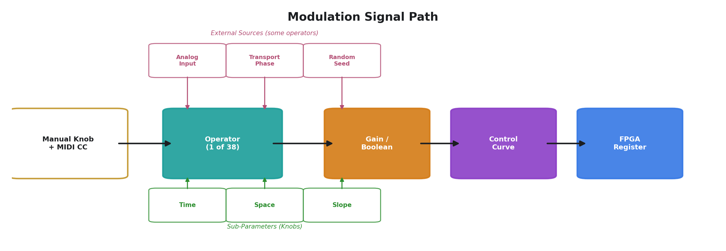
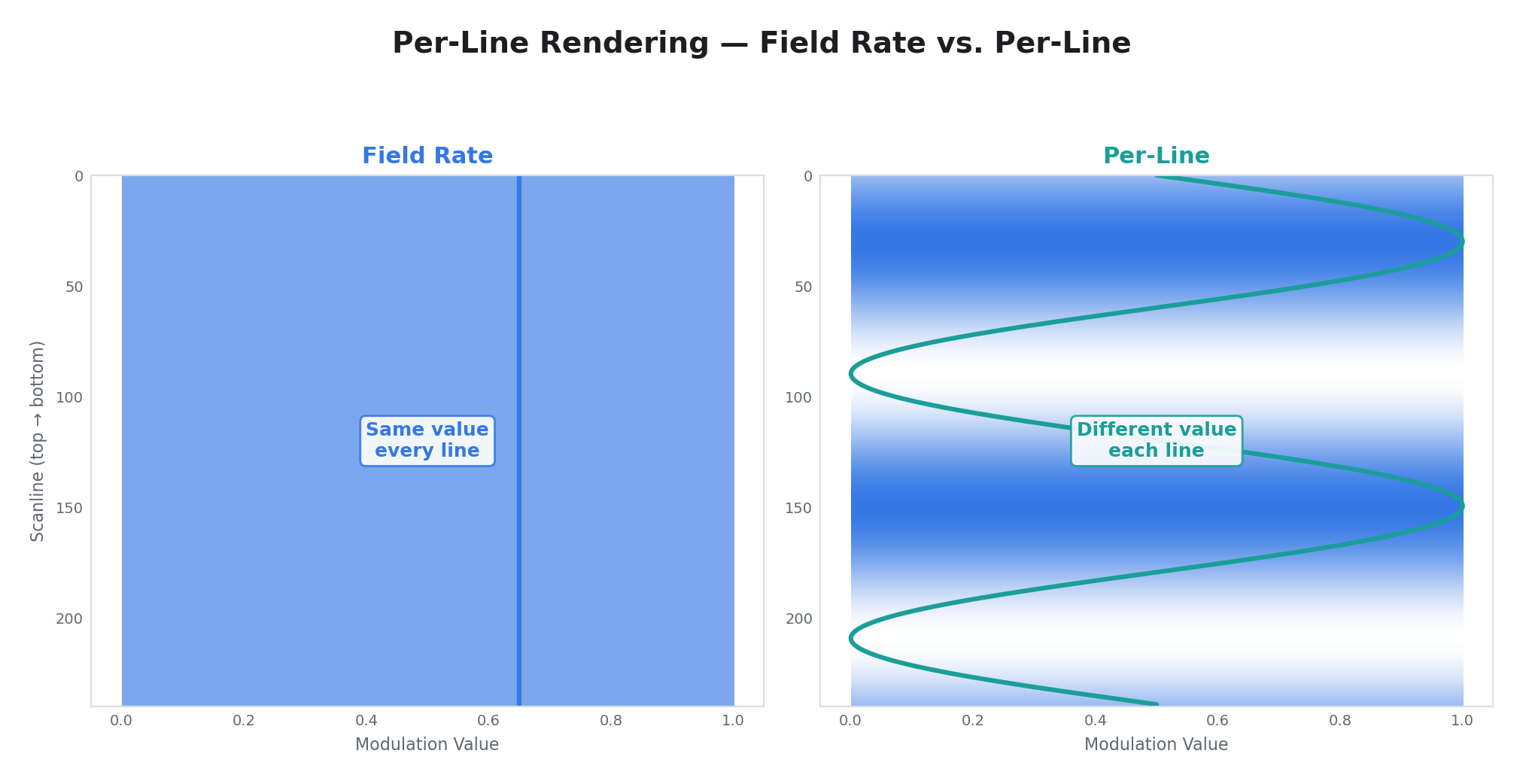
Each modulator updates once per video field (approximately 50 or 60 times per second depending on the video standard). Some operators also produce per-line output — a different value for every scanline within the field — which allows modulation to vary spatially across the frame.
The velocity gate is an optional final stage that applies MIDI note velocity to the output. When a MIDI note-on targeting that modulator is active (note 0 for P1, note 1 for P2, etc.), the note's velocity value scales the output. In linear mode, velocity is added to the output as an offset. In boolean mode, any active note with non-zero velocity forces the output to maximum (fully on). When no note is active, the velocity gate has no effect.
Important: The transport starts in the stopped state on power-up. Most operators produce no modulation output while the transport is stopped — only the manual knob position and MIDI CC offset are applied. Press the Play button or send a MIDI Start message to begin modulation. CV Input and Audio Input are the only operators that produce output regardless of transport state.
The Three Parameters
Every operator receives three control values from dedicated knobs on the Videomancer front panel:
| Parameter | Knob | Role |
|---|---|---|
| Time | M1 | Controls rate or speed — how fast the operator evolves. For oscillators, this is the period. For followers, it is the slew rate. For physics simulations, it controls a force constant. |
| Space | M2 | Controls amplitude or depth — how much the operator's output affects the target parameter. Often labeled "Gain" or "Depth." |
| Slope | M3 | Controls character or shape — which waveshape, which input channel, how much chaos, which rule. This is the qualitative parameter that changes what kind of signal the operator produces. |
The exact meaning of each parameter depends on the active operator. The display labels update automatically when you change operators, so you always see what Time, Space, and Slope do for the current selection.
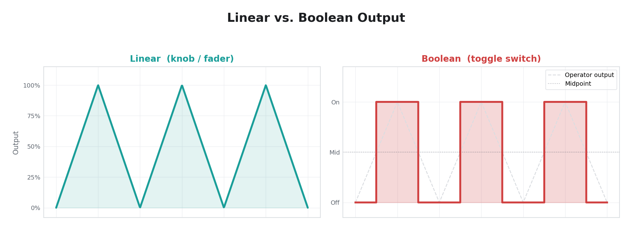
Linear vs. Boolean
Modulators operate in one of two output modes:
- Linear: Outputs a continuous value across the full range. Used for knobs and faders.
- Boolean: Outputs 0 or 1. Used for toggle switches. If the combined manual + operator output is at or above the midpoint (512), the toggle is "on." Below the midpoint, it is "off."
Operator Reference
The 39 operators are grouped by category below. Use this index to find an operator by its numeric ID. The Display column shows the single-character indicator that appears on the Motion screen next to each modulator channel.
| ID | Operator | Display | Category | Per-line |
|---|---|---|---|---|
| 0 | Disabled | · | — | — |
| 1 | Free LFO | L | Oscillators | No |
| 2 | Sync LFO | S | Oscillators | No |
| 3 | CV Input | C | External Input | Yes |
| 4 | Audio Input | A | External Input | Yes |
| 5 | Random | R | Random & Chaos | No |
| 6 | Envelope | E | Envelopes & Followers | No |
| 7 | Sample & Hold | H | Envelopes & Followers | No |
| 8 | Trigger Env | T | Envelopes & Followers | No |
| 9 | Step Seq | Q | Sequencing & Rhythm | No |
| 10 | FFT Band | F | Envelopes & Followers | No |
| 11 | H Displace | D | Spatial (disabled) | No |
| 12 | Turing Machine | U | Random & Chaos | No |
| 13 | Bouncing Ball | B | Physics | No |
| 14 | Logistic Map | X | Random & Chaos | No |
| 15 | Euclidean Rhythm | Y | Sequencing & Rhythm | No |
| 16 | Motion LFO | M | Oscillators | No |
| 17 | V Gradient | G | Spatial (disabled) | No |
| 18 | Comparator | K | Envelopes & Followers | Yes |
| 19 | Pendulum | N | Physics | No |
| 20 | Drift | W | Random & Chaos | No |
| 21 | Ring Mod | * | External Input | Yes |
| 22 | Cellular | # | Random & Chaos | No |
| 23 | Pulse Width | P | Oscillators | No |
| 24 | Peak Hold | J | Envelopes & Followers | Yes |
| 25 | Field Accum | I | Envelopes & Followers | No |
| 26 | Slew Limiter | / | Envelopes & Followers | No |
| 27 | Perlin Noise | ~ | Random & Chaos | No |
| 28 | Wavefolder | Z | Oscillators | No |
| 29 | Clock Div | V | Sequencing & Rhythm | No |
| 30 | Prob Gate | ? | Sequencing & Rhythm | No |
| 31 | Quantizer | O | Envelopes & Followers | Yes |
| 32 | Mouse | m | USB HID Input | No |
| 33 | Keyboard | k | USB HID Input | No |
| 34 | Gamepad | g | USB HID Input | No |
| 35 | Tablet | t | USB HID Input | No |
| 36 | Joystick | ? | USB HID Input | No |
| 37 | Sensor | ? | USB HID Input | No |
| 38 | MIDI Turing | ? | Random & Chaos | No |
Oscillators
These operators generate periodic waveforms. They are the workhorses of modulation — use them whenever you want a parameter to move back and forth in a repeating pattern.
0 — Disabled
| Parameter | Label | Function |
|---|---|---|
| Time | Time | (unused) |
| Space | Space | (unused) |
| Slope | Slope | (unused) |
Per-line: No
Passthrough. The modulator outputs the manual knob position plus any MIDI CC offset, with no modulation applied. This is the default state — select it to return a channel to manual control.
1 — Free LFO
| Parameter | Label | Function |
|---|---|---|
| Time | Rate | Oscillator period. Fully clockwise = 50 ms (fast). Fully counter-clockwise = 20 seconds (slow). The rate response is weighted so that most of the knob's travel covers the slow-to-moderate range, with fast rates concentrated near the top. |
| Space | Depth | Output amplitude. At zero, the oscillator runs but produces no output. At maximum, the full modulation range is used. |
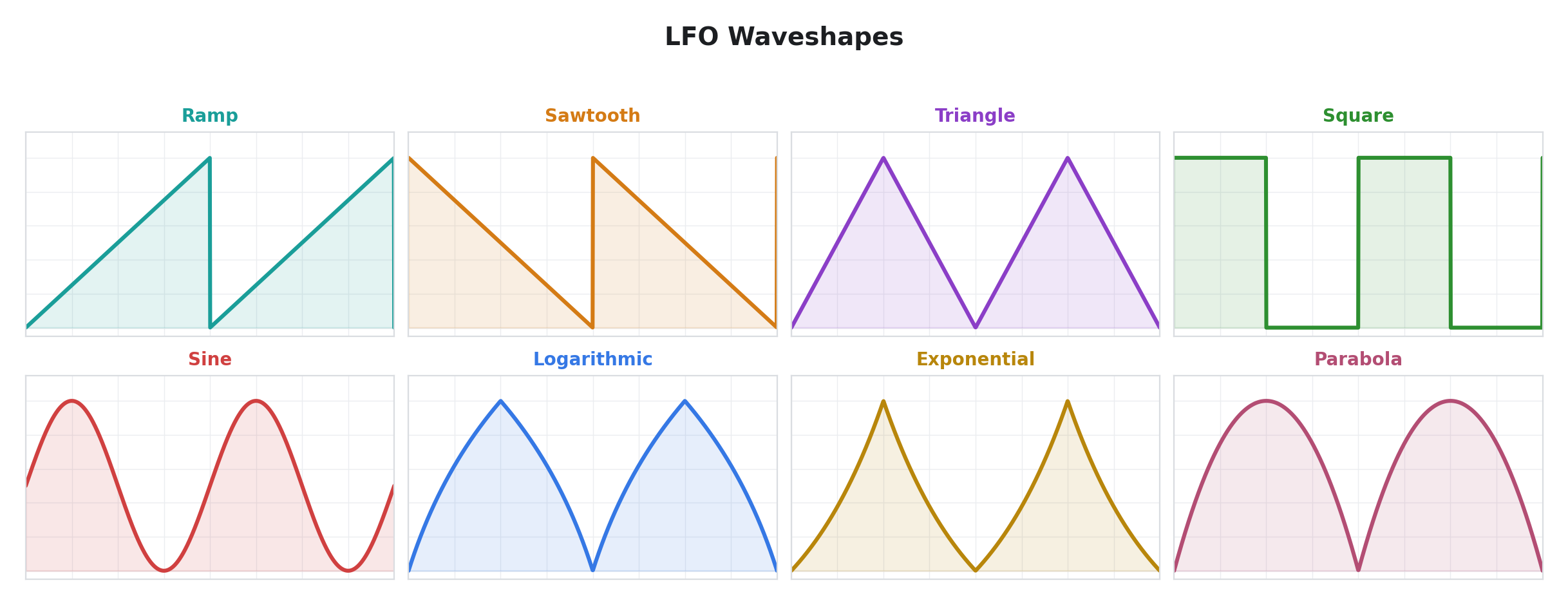
| Slope | Wave | Waveshape select. Eight shapes are available, evenly spaced across the knob: ramp, sawtooth, triangle, square, sine, logarithmic, exponential, and parabola. |
Per-line: No
A low-frequency oscillator. This is the most straightforward modulation source — a repeating waveform at a controllable rate. The oscillator does not lock to any external clock, but it does respect transport state: it only runs while the transport is playing. When the transport stops, Free LFO resets its phase to zero. When the transport pauses, the output freezes at its current value. When playback resumes from a pause, the oscillator continues from where it left off; when playback starts from a stop, it begins fresh from phase zero.
The eight waveshapes cover the fundamental periodic functions. Triangle and sine produce smooth, rounded motion. Square produces hard switching between two values (useful for toggling effects on and off rhythmically). Ramp and sawtooth produce asymmetric sweeps — one direction slow, the other instant. Logarithmic and exponential produce curves that spend more time near one extreme than the other. Parabola produces a rounded bounce shape.
2 — Sync LFO
| Parameter | Label | Function |
|---|---|---|
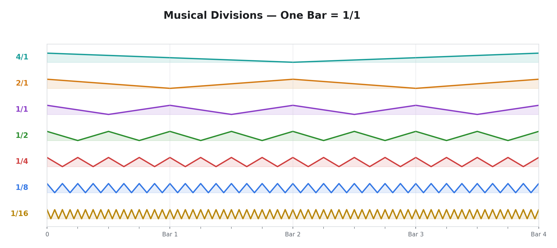
| Time | Division | Musical time division. Sixteen divisions from 32 bars (very slow) down to 1/16 note (fast): 32/1, 16/1, 8/1, 4/1, 3/1, 2/1, 3/2, 1/1, 3/4, 1/2, 3/8, 1/3, 1/4, 1/6, 1/8, 1/16. Dotted and triplet divisions are included. |
| Space | Depth | Output amplitude. |
| Slope | Wave | Waveshape select (same eight shapes as Free LFO). |
Per-line: No
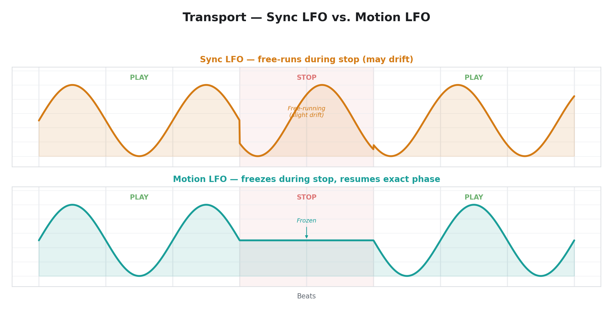
A tempo-synced LFO whose speed is derived from the current BPM. Like Free LFO, this oscillator only advances when the transport is playing — its output drops to zero when the transport stops, and freezes at its current value when the transport pauses. The waveform stays in rhythmic relationship to the beat.
The musical divisions are multiplicative: at 1/1 division, the oscillator completes one full cycle per bar. At 1/4, it completes four cycles per bar (quarter-note rate). At 4/1, it takes four bars to complete one cycle. Dotted divisions (3/2, 3/4, 3/8) and triplet divisions (1/3, 1/6) provide swing and polyrhythmic relationships.
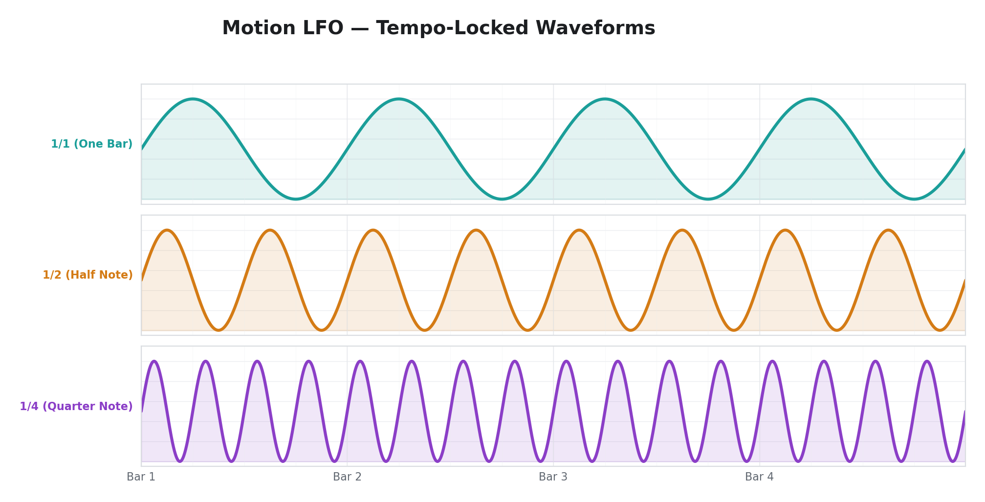
16 — Motion LFO
| Parameter | Label | Function |
|---|---|---|
| Time | Division | Musical time division (same sixteen divisions as Sync LFO). |
| Space | Depth | Output amplitude. |
| Slope | Wave | Waveshape select (eight shapes). |
Per-line: No
A transport-locked LFO that follows the transport position exactly rather than running its own internal clock. The distinction from Sync LFO matters: Sync LFO runs at the same speed as the transport but can drift slightly over time because it runs its own phase accumulator derived from BPM. Motion LFO is perfectly phase-locked to the transport — no drift, no jitter. If you stop and restart the transport, Motion LFO snaps to the exact same position in the waveform every time.
Both Sync LFO and Motion LFO output zero when stopped and freeze when paused. The practical difference is accuracy: use Motion LFO when you need guaranteed phase lock to the transport. Use Sync LFO when BPM-relative speed is sufficient and exact phase alignment is not critical.
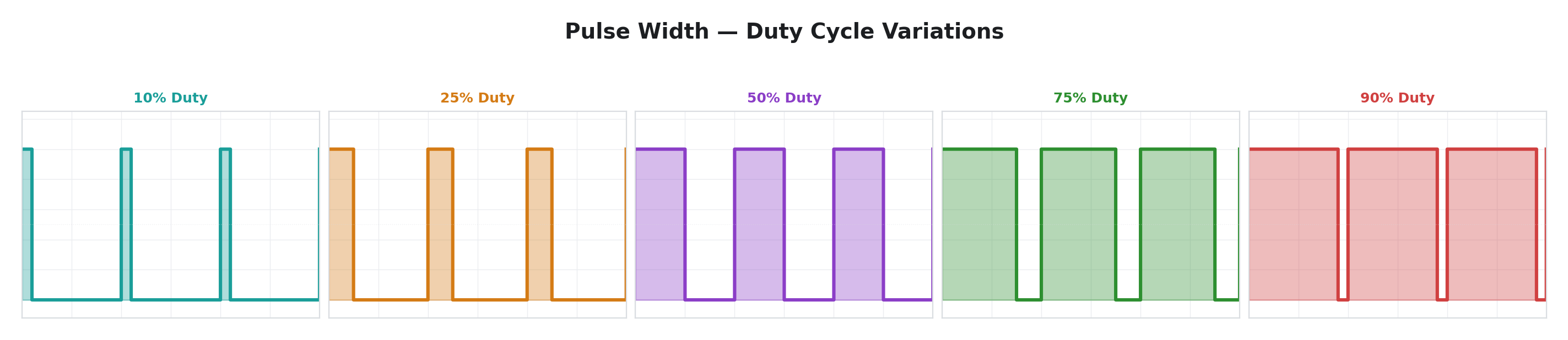
23 — Pulse Width
| Parameter | Label | Function |
|---|---|---|
| Time | Rate | Oscillator period (same weighted rate curve as Free LFO, 50 ms–20 s). |
| Space | Depth | Output amplitude, centered around the midpoint. |
| Slope | Width | Duty cycle. Fully counter-clockwise = 0% (always low). Center = 50% (symmetric square wave). Fully clockwise = 100% (always high). |
Per-line: No
A variable-duty-cycle oscillator. Where a standard square wave spends equal time high and low, Pulse Width lets you skew the ratio. At 50% duty, this produces a standard square wave. As you move toward 0% or 100%, the "on" portion shrinks to a brief pulse or stretches to nearly continuous. The output swings symmetrically above and below the midpoint, with the swing range set by the Depth knob.
Pulse Width is useful for rhythmic gating effects where you want control over how long the "on" portion lasts relative to the cycle — something the square waveshape in Free LFO cannot do.
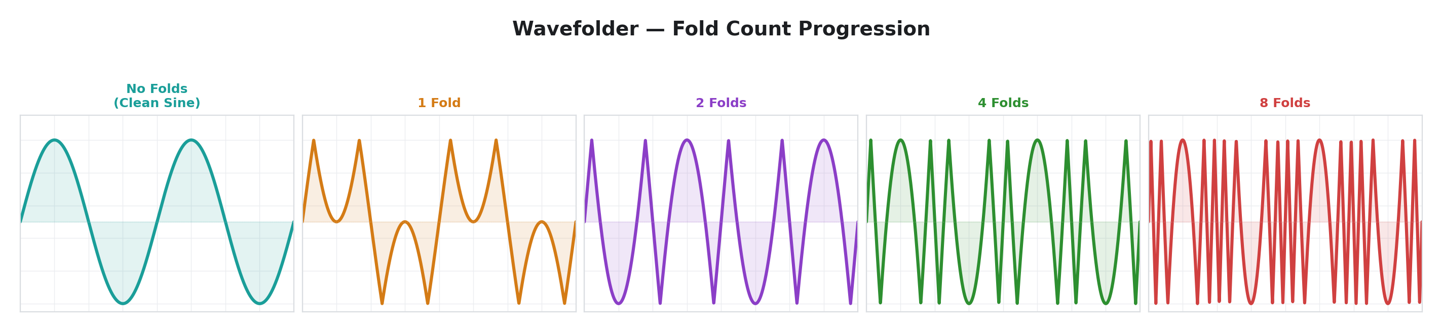
28 — Wavefolder
| Parameter | Label | Function |
|---|---|---|
| Time | Rate | Oscillator period (weighted rate curve, 50 ms–20 s). |
| Space | Folds | Fold count. Fully counter-clockwise = no folding (clean sine wave). Fully clockwise = 8 folds. |
| Slope | Symmetry | Fold center offset. Center = symmetric folding. Turning the knob in either direction shifts the fold center, producing asymmetric waveforms. |
Per-line: No
An internal sine oscillator whose output is passed through a wavefolder. Wavefolding works by amplifying the signal until it exceeds the normal output range, then reflecting ("folding") the excess back inward — like folding a piece of paper. One fold turns a sine wave into a shape with two peaks per cycle. Two folds produce four peaks. Eight folds produce a dense, complex waveform with sixteen zero-crossings per cycle from a single underlying sine.
The Symmetry control shifts where the fold boundary sits. At center, the folding is symmetric around the midpoint and the waveform is balanced. Offsetting the symmetry makes one half of each fold wider than the other, producing asymmetric harmonics.
Wavefolder is the go-to operator when you want complex, harmonically rich modulation from a single oscillator. At low fold counts, the output retains the smooth character of a sine wave with gentle distortion. At high fold counts, it becomes a dense, textured waveform that sits between periodic and chaotic.
External Input
These operators read external signals — CV (control voltage) or audio — from Videomancer's analog input jacks. They turn external signals into modulation sources.
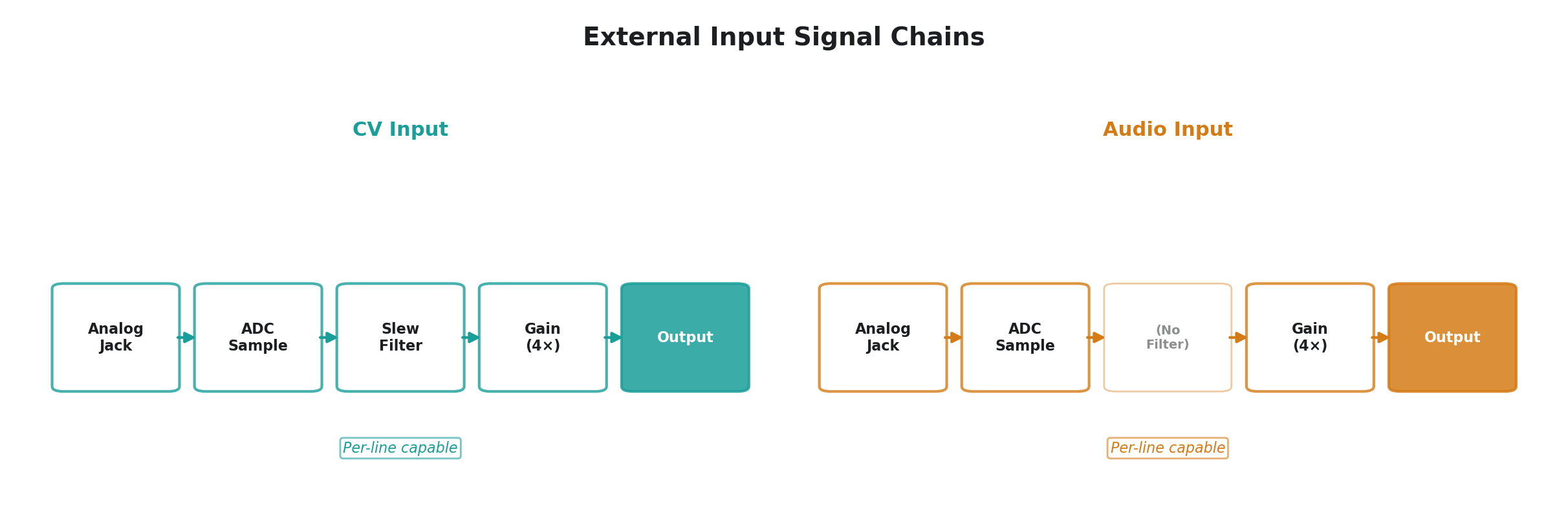
3 — CV Input
| Parameter | Label | Function |
|---|---|---|
| Time | Slew | Smoothing rate. Fully counter-clockwise = instant response (no filtering). Fully clockwise = very slow response (heavy lowpass). |
| Space | Gain | Output amplitude, 4× range. Unity gain at about 25% of travel. Maximum = 4× amplification. |
| Slope | Channel | Input channel select. Six options across the knob range: channels 1–4 individually, or mixed pairs (ch1+2, ch3+4). |
Per-line: Yes
Reads a control voltage from one of Videomancer's analog inputs. The signal passes through a smoothing filter controlled by the Slew knob to remove noise or to intentionally smooth fast-moving inputs into slower gestures. The 4× gain range lets you amplify small input signals to fill the full modulation range.
In per-line mode, each scanline reads its own input sample, so the modulation varies spatially across the frame — different parts of the image see different modulation values depending on the input signal at that moment in the scan.
4 — Audio Input
| Parameter | Label | Function |
|---|---|---|
| Time | Slew | (Unused — this operator does not apply slew filtering. The knob has no effect.) |
| Space | Gain | Output amplitude, 4× range. |
| Slope | Channel | Input channel select (same six options as CV Input). |
Per-line: Yes
Identical to CV Input but with no slew filtering — the raw input signal passes through at full bandwidth regardless of the Time knob position. Use this when the input is an audio-rate signal and you want the modulation to follow every cycle of the waveform rather than tracking just the envelope. The per-line variant is particularly useful here — it maps the instantaneous audio waveform onto the vertical dimension of the video frame.
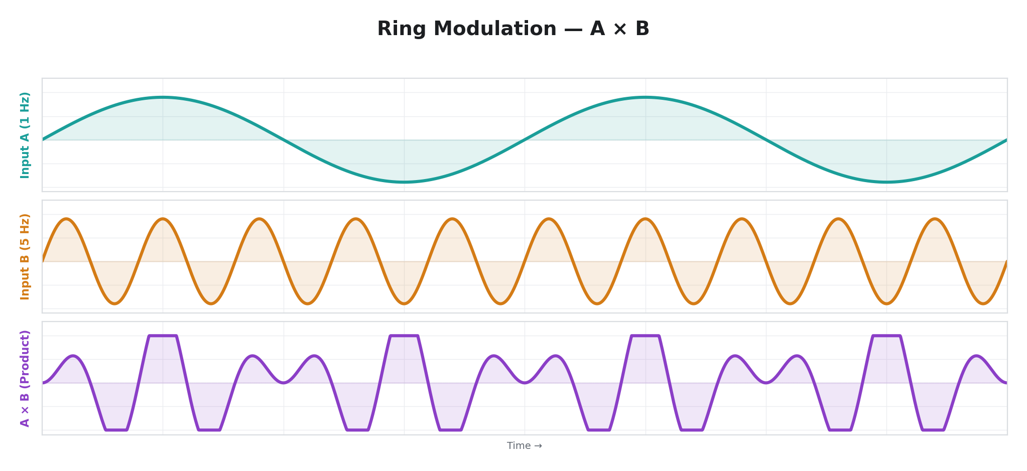
21 — Ring Mod
| Parameter | Label | Function |
|---|---|---|
| Time | Slew | Output smoothing. Fully counter-clockwise = instant response. Fully clockwise = very slow response. |
| Space | Gain | Output amplitude. |
| Slope | Channel | Channel pair. Lower half of the knob = ch1 × ch2. Upper half = ch3 × ch4. |
Per-line: Yes
Multiplies two analog input channels together, centered around the midpoint. This is ring modulation — the output contains new frequencies derived from the interaction of the two inputs, but neither input appears on its own. If both inputs are simple waveforms, the output produces tones not present in either one.
The per-line variant multiplies the two channels at each scanline independently, creating spatially varying modulation patterns driven by the interaction of two external signals.
Envelopes & Followers
These operators track the amplitude or threshold crossings of external signals. They convert dynamic input signals into smooth control signals.
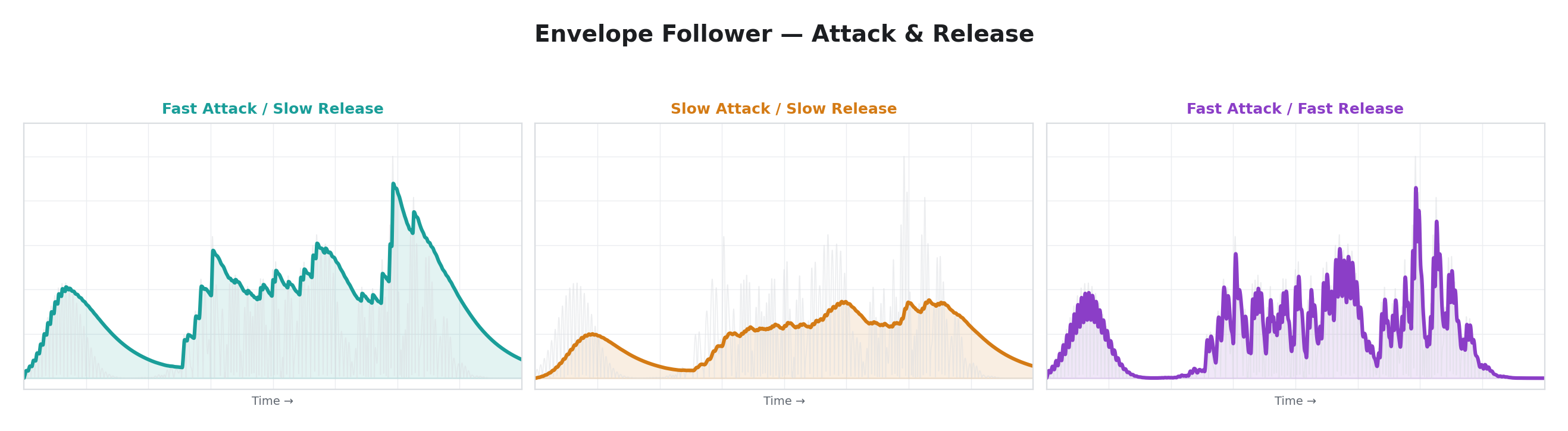
6 — Envelope
| Parameter | Label | Function |
|---|---|---|
| Time | Attack | Attack rate. Fully counter-clockwise = instant (tracks peaks immediately). Fully clockwise = very slow (output rises gradually toward new peaks). |
| Space | Release | Release rate. Fully counter-clockwise = instant (drops immediately when input falls). Fully clockwise = very slow (output holds peaks and decays gradually). |
| Slope | Channel | Input channel select. |
Per-line: No
An envelope follower that tracks the strength of an analog input signal. The input is measured as distance from the midpoint, then processed through a peak detector with independent attack and release rates. When the input exceeds the current output, the output rises at the attack rate. When the input falls below the current output, the output decays at the release rate.
Fast attack and slow release produce a classic "peak hold" envelope that captures transients and releases slowly — ideal for making a parameter respond to the loudness of audio input. Fast attack and fast release produce a signal that closely tracks the input waveform's amplitude.
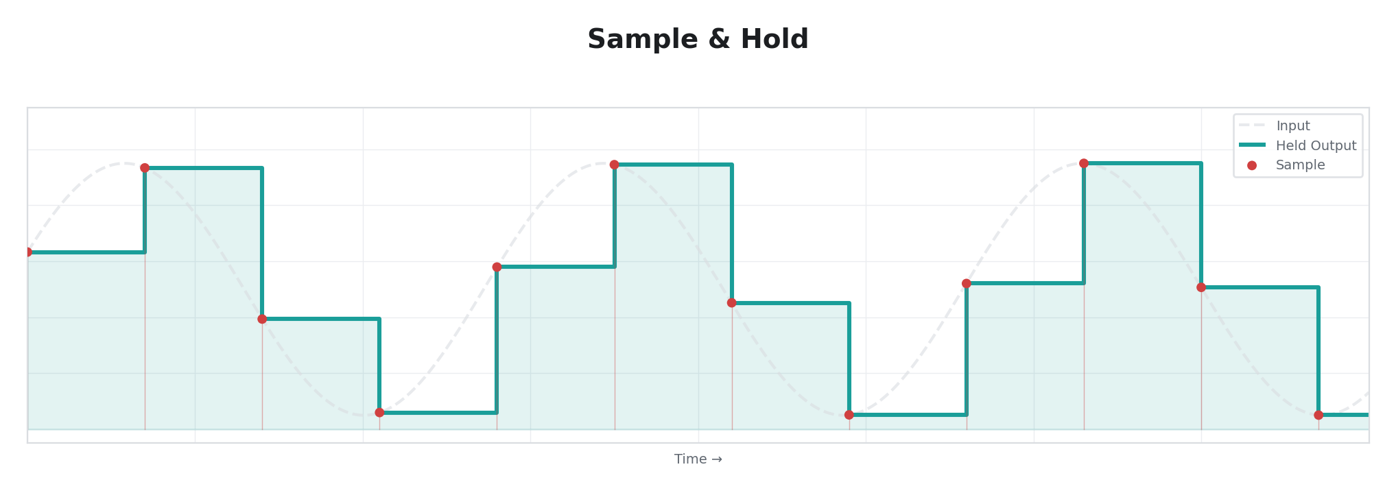
7 — Sample & Hold
| Parameter | Label | Function |
|---|---|---|
| Time | Rate | Clock period (50 ms–20 s). |
| Space | Gain | Output amplitude. |
| Slope | Channel | Input channel select. |
Per-line: No
A classic sample-and-hold circuit. An internal clock runs freely at the rate set by Time. On each clock tick, a new sample is captured from the selected input channel, and that value is held constant until the next tick. The result is a staircase waveform — a series of flat plateaus at random-seeming levels determined by whatever the input signal happened to be at each sample moment.
Sample & Hold is one of the fundamental building blocks of analog synthesizer modulation. It turns a continuous signal into discrete steps, creating unpredictable but input-correlated patterns.
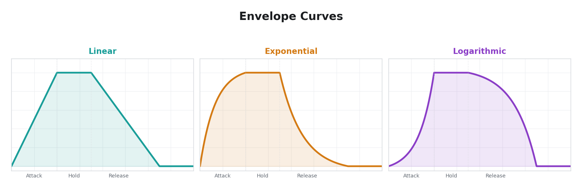
8 — Trigger Env
| Parameter | Label | Function |
|---|---|---|
| Time | Attack | Attack rate. Fully counter-clockwise = instant. Fully clockwise = very slow. |
| Space | Release | Release rate. Fully counter-clockwise = instant. Fully clockwise = very slow. |
| Slope | Curve | Envelope shape. Three curves across the knob range: linear, exponential, and logarithmic. |
Per-line: No
A MIDI-triggered attack/release envelope. When a MIDI note-on message arrives, the output ramps from zero to maximum at the attack rate. When a note-off arrives, it ramps back to zero at the release rate. Three curve shapes control the contour of the ramp: linear (constant rate), exponential (starts fast, decelerates), and logarithmic (starts slow, accelerates).
This is the operator to use when you want a parameter to respond to MIDI keyboard or sequencer events — press a key and the parameter sweeps up, release it and it sweeps back down.
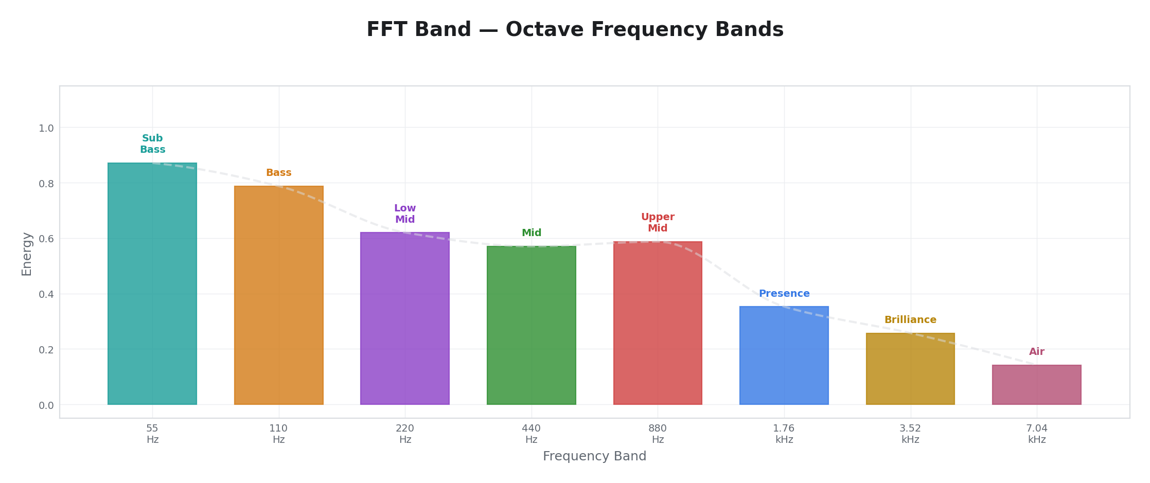
10 — FFT Band
| Parameter | Label | Function |
|---|---|---|
| Time | Slew | Envelope smoothing. Fully counter-clockwise = instant response. Fully clockwise = very slow response. |
| Space | Gain | Output amplitude. |
| Slope | Band | (Display only — does not affect audio processing. The display shows a band label but the output always tracks broadband energy.) |
Per-line: No
Note: Despite its name, FFT Band does not perform frequency-selective analysis in the current firmware. It reads broadband energy from Input 1 (rectified and scaled) and tracks it with an envelope follower controlled by the Slew knob. The Slope knob's "Band" label changes the display but has no effect on the audio processing — all band selections produce the same output. This operator functions as a simple audio energy follower on Input 1.
Use FFT Band when you want a parameter to respond to the overall loudness of an audio signal on Input 1. For true frequency-selective behavior, apply external bandpass filtering before the input jack.
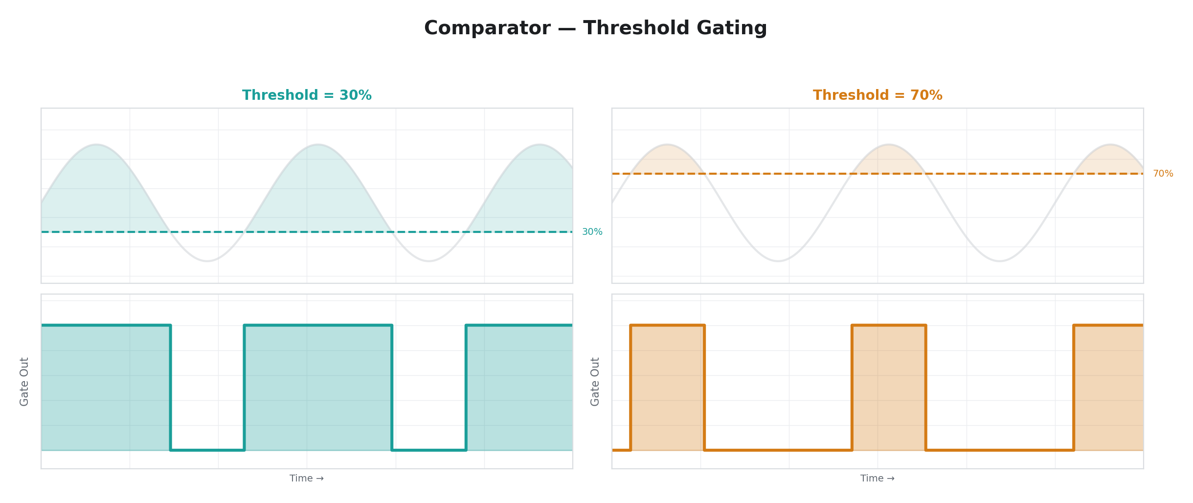
18 — Comparator
| Parameter | Label | Function |
|---|---|---|
| Time | Thresh | Comparison threshold. Fully counter-clockwise = lowest threshold (almost everything passes). Fully clockwise = highest threshold (only the strongest signals pass). |
| Space | Gain | Output amplitude. |
| Slope | Channel | Input channel select. |
Per-line: Yes
A threshold comparator. The input signal is compared against the threshold value set by Time. When the input is at or above the threshold, the output is maximum. When below, the output is zero. There is no smoothing, no hysteresis — just a hard binary decision based on voltage level.
In per-line mode, the comparison happens independently at each scanline, so the output creates a spatial pattern: parts of the frame where the input signal exceeds the threshold are "on," and parts where it falls below are "off." This is essentially a real-time luminance key applied to the modulation signal.
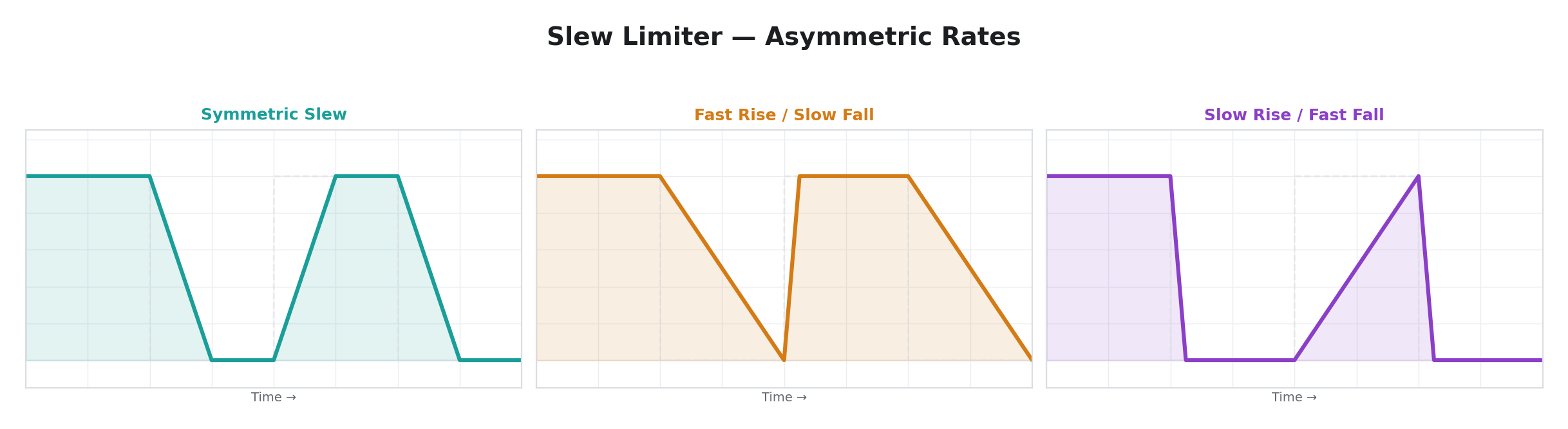
26 — Slew Limiter
| Parameter | Label | Function |
|---|---|---|
| Time | Rise | Maximum rise rate. Fully counter-clockwise = nearly frozen (very slow rise). Fully clockwise = instant (follows input upward immediately). |
| Space | Gain | Output amplitude. |
| Slope | Fall | Maximum fall rate. Same scale as Rise but applied to downward movement. |
Per-line: No
A rate-limited follower of an analog input signal (always Input 1). The output tracks the input, but the maximum speed at which it can move upward (rise) and downward (fall) is independently limited. If the input jumps instantly from low to high, the output ramps up at the rise rate. If the input drops, the output ramps down at the fall rate.
Asymmetric slew rates produce distinctive motion profiles. Fast rise and slow fall creates a signal that snaps to peaks and gently decays — useful for making parameters respond quickly to transients but recover slowly. Slow rise and fast fall creates the opposite: sluggish response to increasing input but instant response to decreasing input.
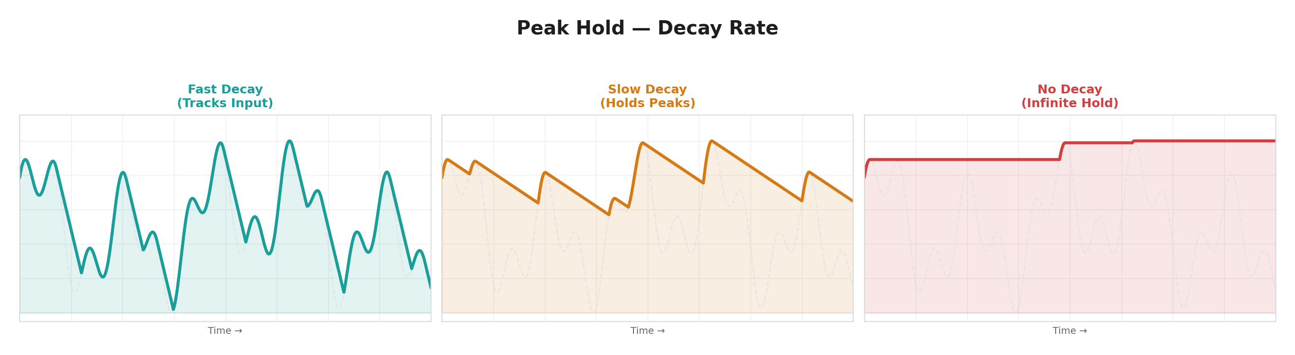
24 — Peak Hold
| Parameter | Label | Function |
|---|---|---|
| Time | Decay | Decay rate. Fully counter-clockwise = instant decay (output tracks input directly). Fully clockwise = infinite hold (peaks are captured and never decay). |
| Space | Gain | Output amplitude. |
| Slope | Channel | Input channel select. |
Per-line: Yes
A peak detector with configurable hold time. New peaks in the input are captured instantly — the output jumps to match. Between peaks, the output decays toward zero at the rate set by Decay. With the knob fully counter-clockwise (fastest decay), the output simply follows the input. With the knob fully clockwise (no decay), peaks are held indefinitely, creating a ratchet effect where the output can only go up.
The per-line variant outputs the maximum of the held peak and the current scanline's input value, so per-line variation from the input signal is preserved while the held peak provides a floor.
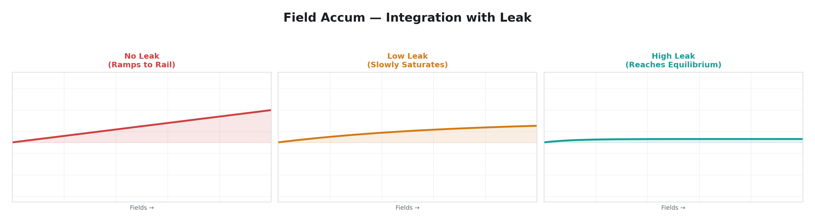
25 — Field Accum
| Parameter | Label | Function |
|---|---|---|
| Time | Rate | Integration rate. Controls how much of the input signal is added per field (1/64 at minimum, 1/1 at maximum). |
| Space | Gain | Output amplitude. |
| Slope | Leak | Drain rate and input channel select. Fully counter-clockwise = no leak (pure integrator, value latches). Fully clockwise = fast drain (output returns to center quickly). |
Per-line: No
Field Accum operates as an integrator: it continuously adds the input signal from Input 1 (minus the midpoint) to a running total. Over time, the total drifts upward if the input is above center, or downward if below. The Leak parameter applies a constant drain that pulls the total back toward center, preventing it from railing at the extremes.
With no leak and a steady input, Field Accum ramps steadily in one direction until it hits the rail — useful for generating slow ramps locked to an input signal. With moderate leak, it produces a smoothed, sluggishly-responding version of the input. With high leak, the output tracks the input loosely, acting as a weighted running average.
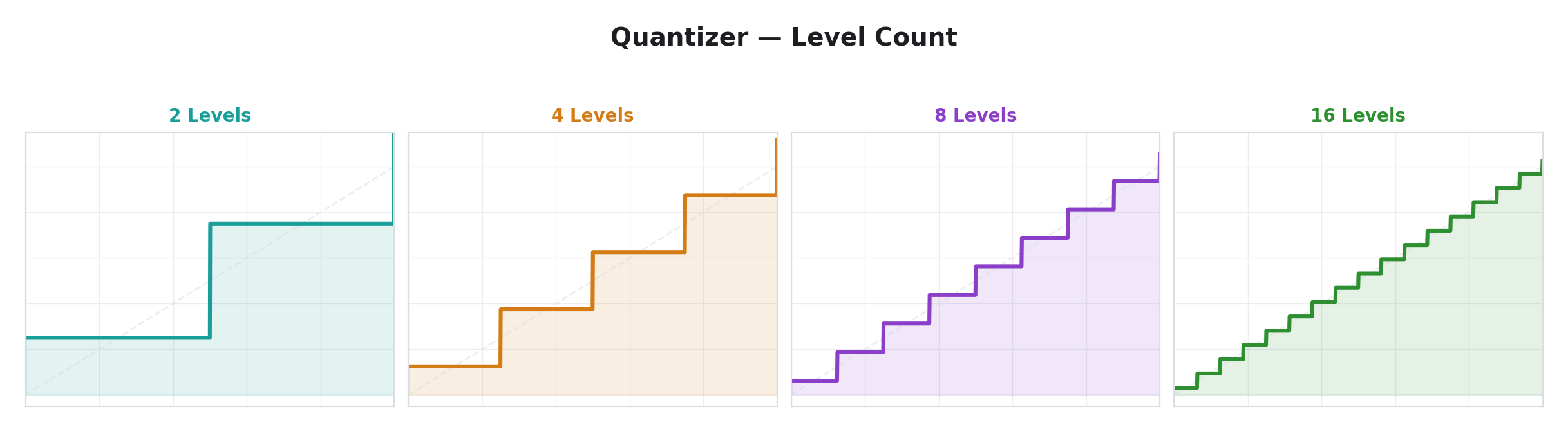
31 — Quantizer
| Parameter | Label | Function |
|---|---|---|
| Time | Levels | Number of quantization levels (2 at minimum, 32 at maximum). |
| Space | Gain | Output amplitude. |
| Slope | Channel | Input channel select. |
Per-line: Yes
Snaps the input to one of N evenly-spaced levels, producing a staircase output. The continuous input range is divided into N equal bins, and every input value within a bin is mapped to that bin's center value.
At 2 levels, the output is binary — effectively a comparator at the midpoint. At 32 levels, the output is a fine staircase that closely tracks the input but with visible quantization steps. The creative sweet spot is often between 4 and 12 levels, where the staircase structure is clearly visible in the modulated parameter.
Quantizer is the only operator in this group with per-line rendering. Each scanline is quantized independently, so the staircase pattern applies spatially — a smooth gradient in the input becomes a series of discrete spatial bands in the output.
Random & Chaos
These operators produce non-repeating or quasi-periodic patterns. They range from smooth noise to mathematical chaos.
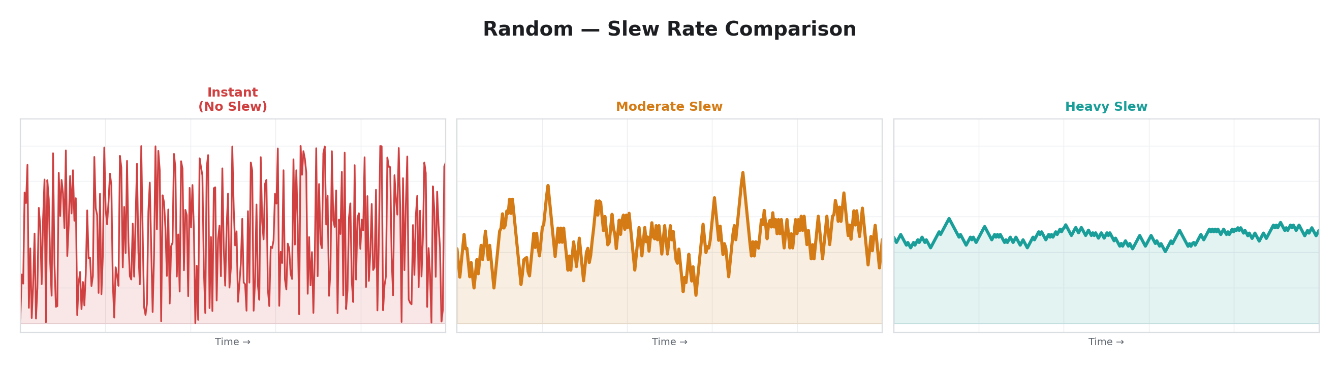
5 — Random
| Parameter | Label | Function |
|---|---|---|
| Time | Rise | Rise slew rate. Fully counter-clockwise = instant. Fully clockwise = very slow. |
| Space | Gain | Output amplitude. |
| Slope | Fall | Fall slew rate. Fully counter-clockwise = instant. Fully clockwise = very slow. |
Per-line: No
Generates a new random target value every video field and slews toward it. The slew has independent rise and fall rates — the output moves toward new targets that are above it at the rise rate, and toward targets below it at the fall rate.
With both slew rates at zero (instant), the output jumps to a new random value every field — pure sample-and-hold noise at the field rate. With moderate slew, the output wanders smoothly between random targets. With high slew, the output becomes a slow, lazy random drift.
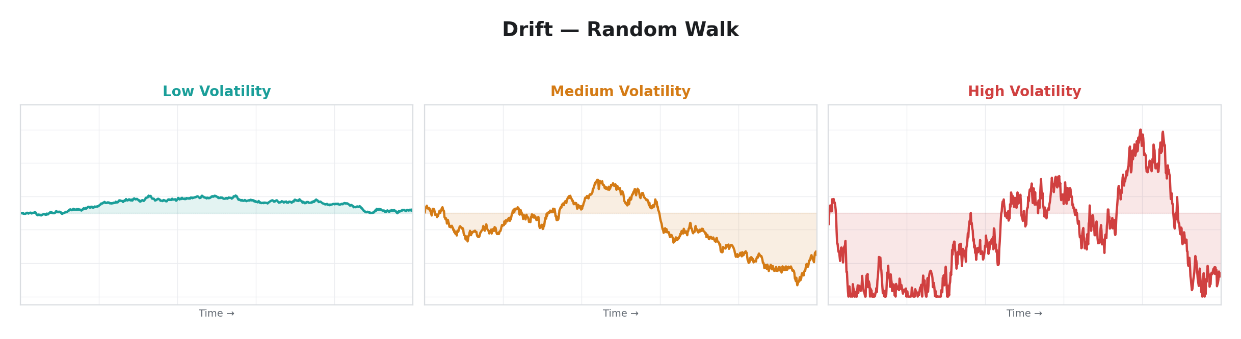
20 — Drift
| Parameter | Label | Function |
|---|---|---|
| Time | Rate | Step size / volatility. Fully counter-clockwise = static (no movement). Fully clockwise = large random steps. |
| Space | Gain | Output amplitude. |
| Slope | Range | Centering pull. Fully counter-clockwise = free walk (no centering). Fully clockwise = tight centering (output stays near middle). |
Per-line: No
Brownian random walk. Each frame, a small random step is added to the current position. A configurable centering force gently pulls the value back toward the midpoint, preventing it from permanently drifting to one extreme.
Drift produces motion that feels organic and aimless — like a leaf blowing in the wind. Unlike Random (which jumps to brand-new targets), Drift moves by small increments from wherever it currently is, so the output is always locally smooth even though its long-term trajectory is unpredictable. The centering force determines whether the walk is bounded (with centering) or truly free-roaming (without).
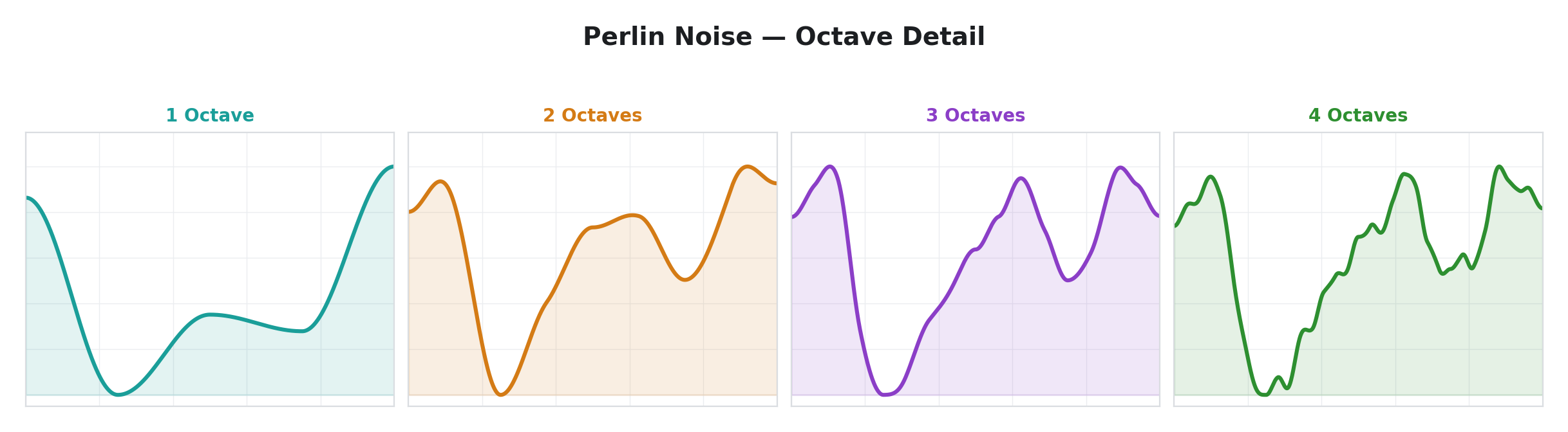
27 — Perlin Noise
| Parameter | Label | Function |
|---|---|---|
| Time | Speed | Evolution rate. Fully counter-clockwise = slow, gradual drift. Fully clockwise = fast, rapidly changing texture. |
| Space | Gain | Output amplitude. |
| Slope | Detail | Octave count. Fully counter-clockwise = 1 octave (smooth, gentle undulation). Fully clockwise = 4 octaves (rough, detailed texture). |
Per-line: No
Smooth, coherent noise inspired by Perlin noise. Unlike Random (which jumps between uncorrelated values) or Drift (which wanders by small steps), Perlin Noise interpolates smoothly between random lattice points, producing motion that is continuous and has no visible "steps" or "jumps."
The Detail parameter adds octave layering — additional noise at higher frequencies is summed with the base noise, creating progressively more complex texture. At one octave, the output is a gentle, wide undulation. At four octaves, it has both slow macro-movement and fast micro-variation, much like natural phenomena such as clouds, terrain, or water surfaces.
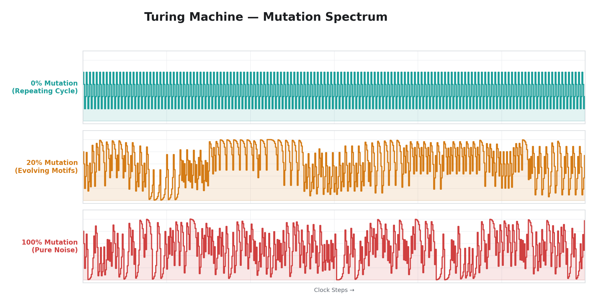
12 — Turing Machine
| Parameter | Label | Function |
|---|---|---|
| Time | Rate | Clock period (50 ms–20 s). |
| Space | Gain | Output amplitude. |
| Slope | Mutate | Mutation probability. Fully counter-clockwise = locked (perfectly repeating cycle). Center = 50% (every other bit is mutated). Fully clockwise = fully random (no pattern memory). |
Per-line: No
A shift-register sequencer inspired by the "Turing Machine" module from modular synthesis. An 8-bit shift register advances one position per clock tick. The new value entering the register is either a deterministic feedback (creating a repeating pseudo-random sequence) or a truly random value — the Mutate parameter controls the probability of mutation.
At zero mutation, the sequence cycles through a fixed 255-step pattern that repeats identically forever. At full mutation, every step is random and the output is pure noise. The creative territory is in between: low mutation produces long sequences that occasionally vary. Moderate mutation creates patterns that evolve gradually — recognizable motifs that drift and transform over time.
38 — MIDI Turing
| Parameter | Label | Function |
|---|---|---|
| Time | Slew | Output smoothing. Fully counter-clockwise = instant jumps (new value appears immediately). Fully clockwise = slow glide (output slews toward the new value over many frames). |
| Space | Gain | Output amplitude. |
| Slope | Mutate | Mutation probability. Same behavior as Turing Machine: fully counter-clockwise = locked loop, fully clockwise = fully random, center = 50% mutation. |
Per-line: No
A variant of the Turing Machine that advances on MIDI note events instead of a free-running clock. The 8-bit shift register only shifts when a new MIDI note-on message is received targeting that modulator — holding a note produces a steady output, and each new note triggers a single step of the sequence.
This makes the modulation rhythmically synchronized to your MIDI performance. Playing a fast arpeggio produces rapid value changes; holding a sustained note keeps the output steady. The Mutate parameter controls the same order-to-chaos spectrum as the standard Turing Machine.
The Slew parameter replaces Rate (since timing is now determined by MIDI input). It controls how quickly the output moves toward each new value — at zero, transitions are instantaneous; at higher values, the output glides smoothly between steps, creating portamento-like modulation contours. Assign MIDI Turing to a video effect parameter and play MIDI notes to step through a pseudo-random sequence. With low mutation, the sequence repeats exactly with each pass through the same note pattern. With moderate mutation, the sequence gradually evolves across performances.
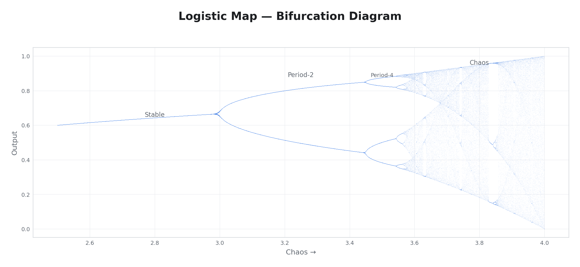
14 — Logistic Map
| Parameter | Label | Function |
|---|---|---|
| Time | Rate | Iteration clock (50 ms–20 s). |
| Space | Gain | Output amplitude. |
| Slope | Chaos | Controls the balance between order and randomness. Fully counter-clockwise = stable, repeating value. Center = oscillation between a few values. Fully clockwise = full chaos (output never repeats). |
Per-line: No
Iterates a simple mathematical equation that produces genuinely chaotic behavior. The Chaos parameter controls whether the system converges to a stable value, oscillates between a few values, or becomes fully unpredictable.
Sweeping Chaos from low to high reveals a characteristic progression: at the low end, the output settles to a single steady value. As you turn the knob further, it begins alternating between two values, then four, then eight. Eventually, the output becomes chaotic — it never repeats, yet it is entirely determined by the equation. At maximum Chaos, the output looks random but follows an underlying mathematical structure.
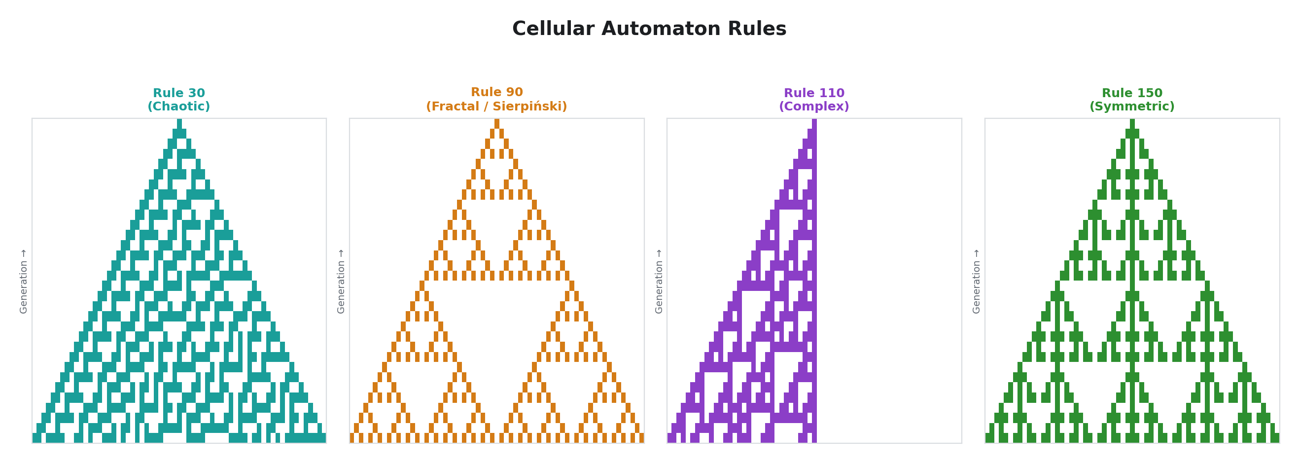
22 — Cellular
| Parameter | Label | Function |
|---|---|---|
| Time | Rate | Generation clock (50 ms–20 s). |
| Space | Gain | Output amplitude. |
| Slope | Rule | Automaton rule select. Four elementary cellular automaton rules across the knob: Rule 30 (chaotic), Rule 90 (fractal/Sierpinski), Rule 110 (complex), Rule 150 (symmetric complex). |
Per-line: No
A one-dimensional cellular automaton. Each generation, every cell's next state is determined by its current state and the states of its two neighbors, according to the selected rule. The output reflects the state of the automaton, scaled to the full modulation range.
These simple rules produce remarkably complex behavior. Rule 30 produces seemingly random output from ordered starting conditions. Rule 90 produces self-similar fractal patterns (the Sierpinski triangle). Rule 110 produces complex patterns with both structured and unpredictable regions. Rule 150 produces complex symmetric structures.
The automaton re-seeds when you change rules (only the center cell starts active), so switching rules initiates a fresh evolution from a known starting condition.
Sequencing & Rhythm
These operators produce structured, repeating patterns — step sequences, rhythmic gates, and clock-derived signals.
9 — Step Seq
| Parameter | Label | Function |
|---|---|---|
| Time | Rate | Clock period (50 ms–20 s). |
| Space | Depth | Output amplitude. |
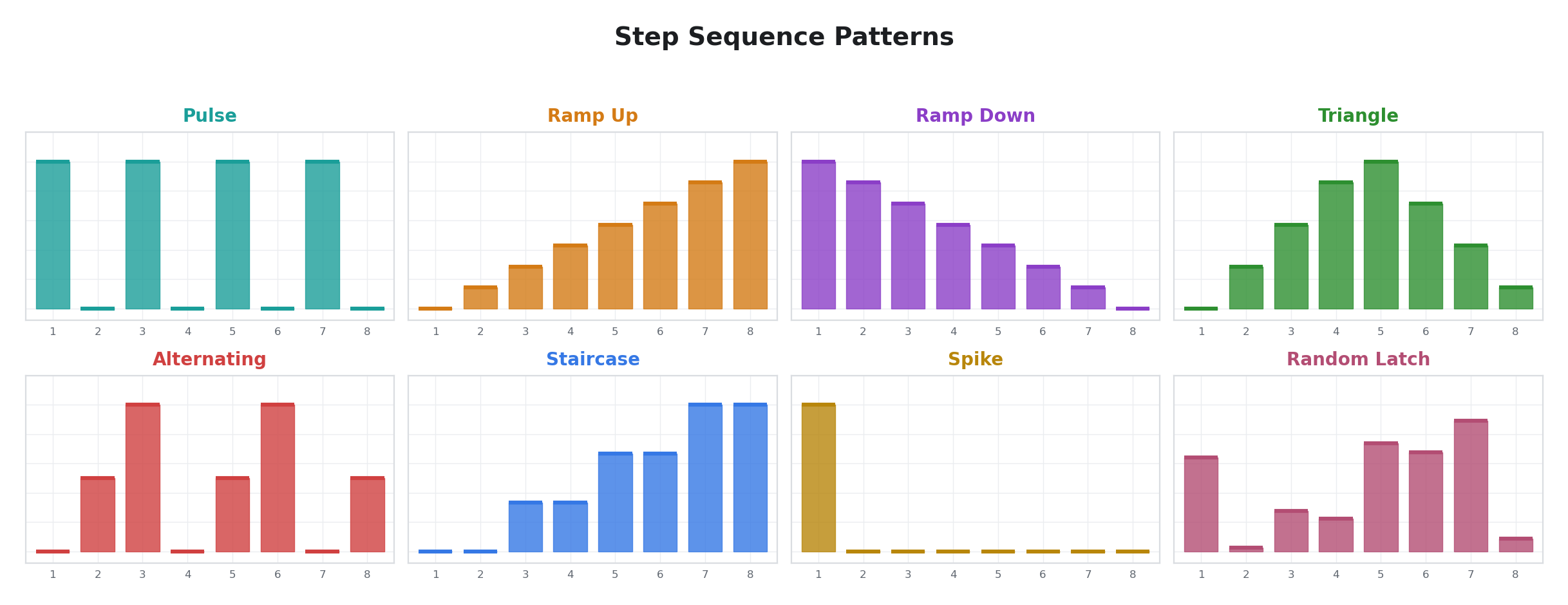
| Slope | Pattern | Pattern select. Eight preset patterns across the knob: pulse, ramp up, ramp down, triangle, alternating, staircase, spike, and random-latch. |
Per-line: No
An 8-step sequencer driven by an internal clock. Each clock tick advances to the next step. Each pattern defines eight fixed output levels that the sequencer cycles through.
The patterns cover common modulation shapes: Pulse alternates between high and low on every step (a regular pulse train at half the sequence rate). Ramp Up and Ramp Down produce ascending and descending staircases. Triangle goes up and back down. Alternating cycles through three levels (low, mid, high) in a shifting pattern. Staircase has four levels, each held for two steps. Spike is a single-step impulse. Random-Latch latches a new random value at each step, producing an 8-step random sequence that changes every cycle.
15 — Euclidean Rhythm
| Parameter | Label | Function |
|---|---|---|
| Time | Rate | Clock period (50 ms–20 s). |
| Space | Gain | Output amplitude. |
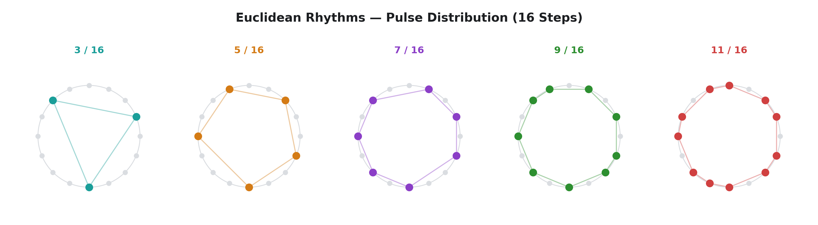
| Slope | Density | Pulse count. Fully counter-clockwise = 0 pulses (silent). Fully clockwise = 16 pulses (all steps active). |
Per-line: No
Generates Euclidean rhythms — patterns where a given number of pulses are distributed as evenly as possible across 16 steps. The algorithm is equivalent to Bjorklund's, the same method that produces many traditional world music rhythms (such as the Cuban tresillo and West African bell patterns) at various step counts.
The output is binary per step (high or low), making this operator ideal for boolean modulation of toggle switches. In linear mode, the output alternates between zero and full scale in the Euclidean pattern.
29 — Clock Div
| Parameter | Label | Function |
|---|---|---|
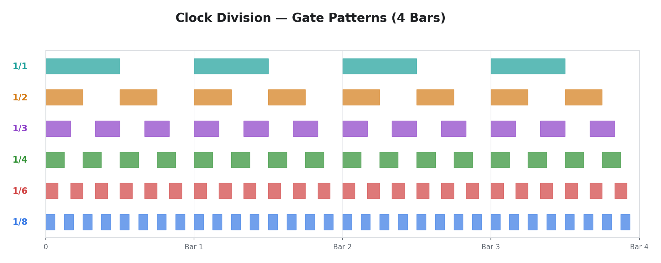
| Time | Division | Division ratio. Fully counter-clockwise = ÷1 (follows transport directly). Fully clockwise = ÷16. |
| Space | Gain | Output amplitude. |
| Slope | Duty | Gate duty cycle. Fully counter-clockwise = shortest possible pulse. Center = 50% (symmetric square). Fully clockwise = nearly 100% (gate stays open almost the entire divided period). |
Per-line: No
An integer clock divider that divides the motion transport phase by a ratio from 1 to 16. The output is a square-wave gate at the divided rate, with a controllable duty cycle. At ÷1, the output toggles at the base transport rate. At ÷4, it toggles at one quarter the rate. At ÷16, it produces one gate cycle for every 16 transport cycles.
Clock Div is the rhythmic complement to Motion LFO. Where Motion LFO produces continuously varying waveforms locked to the transport, Clock Div produces clean, hard-edged gates at related tempos. The Duty parameter controls the gate shape — making it useful for creating rhythmic on/off patterns with precise timing relative to the master clock.
30 — Prob Gate
| Parameter | Label | Function |
|---|---|---|
| Time | Rate | Gate period (50 ms–20 s). |
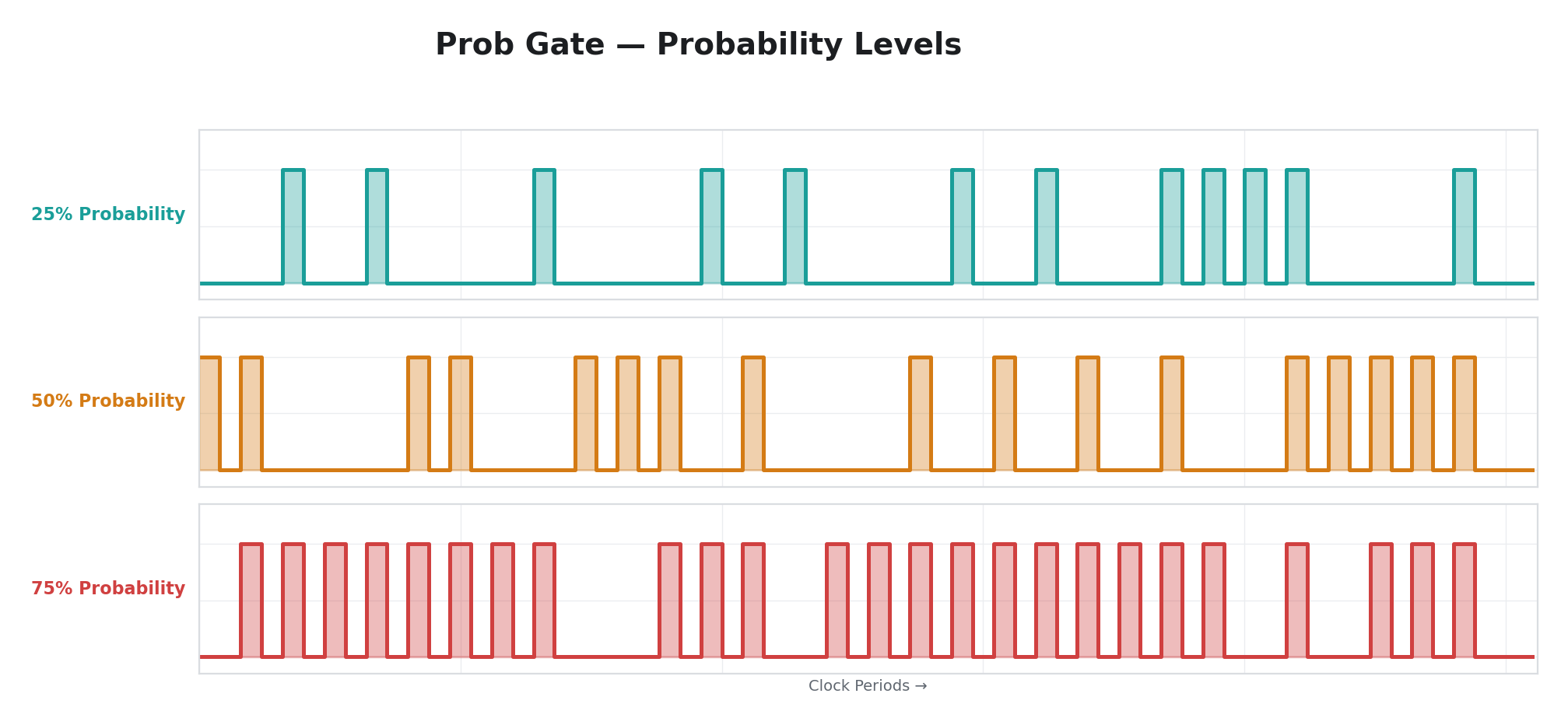
| Space | Prob | Probability of the gate being "high" on any given period (0% = never, 50% = half the time, 100% = always). |
| Slope | Length | Gate length within the period. Controls what fraction of the period the gate stays open when it fires. |
Per-line: No
A probabilistic binary gate. At each period boundary, a random coin flip determines whether the gate will be high or low for the upcoming period. The Prob parameter sets the probability: at 0%, the gate never opens. At 100%, it always opens. At 50%, it opens roughly half the time. The Length parameter controls how long the gate stays open within each period — at full length, the gate fills the entire period; at short length, it produces a brief pulse near the start.
Prob Gate is designed for generative composition — it produces rhythmic on/off patterns that are statistically predictable but not deterministically repeating. Two Prob Gates with different rates and probabilities, assigned to different parameters, create complex polyrhythmic textures that never exactly repeat.
Spatial (Disabled)
These operators are designed to produce values that vary across the video frame rather than (or in addition to) varying over time. Both are currently disabled in firmware and behave as passthrough (identical to Disabled). They are reserved for a future firmware update.
11 — H Displace
| Parameter | Label | Function |
|---|---|---|
| Time | Freq | (unused) |
| Space | Depth | (unused) |
| Slope | Wave | (unused) |
Per-line: No
Note: H Displace is currently disabled in firmware. Selecting it behaves identically to Disabled — the modulator passes through the manual knob position with no modulation applied. This operator is reserved for a future firmware update.
17 — V Gradient
| Parameter | Label | Function |
|---|---|---|
| Time | Freq | (unused) |
| Space | Depth | (unused) |
| Slope | Wave | (unused) |
Per-line: No
Note: V Gradient is currently disabled in firmware. Selecting it behaves identically to Disabled — the modulator passes through the manual knob position with no modulation applied. This operator is reserved for a future firmware update.
Physics
These operators simulate physical systems. They produce the kinds of motion that arise from natural forces — gravity, springs, friction, damping.
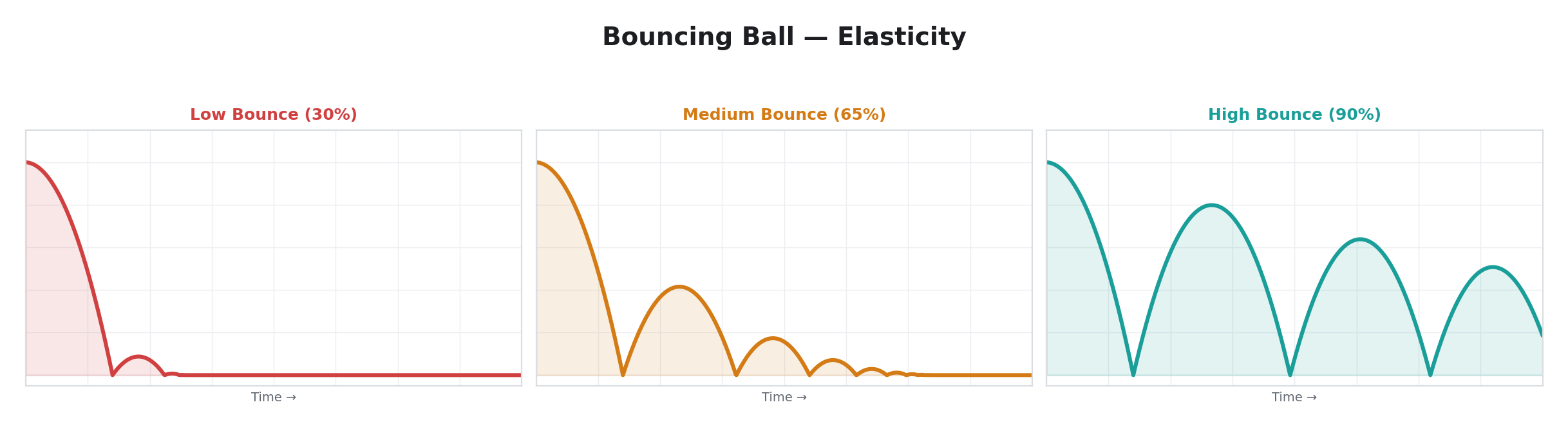
13 — Bouncing Ball
| Parameter | Label | Function |
|---|---|---|
| Time | Gravity | Gravitational acceleration. Fully counter-clockwise = weak gravity (floaty, slow falls). Fully clockwise = strong gravity (fast, violent bounces). |
| Space | Gain | Output amplitude. |
| Slope | Bounce | Elasticity. Fully counter-clockwise = no bounce (ball sticks to floor). Fully clockwise = nearly perfect bounce (ball returns to almost its original height). |
Per-line: No
Simulates a ball bouncing on a floor. The ball starts at the top, falls under gravity, hits the floor, and bounces back. Each bounce is lower than the last (unless Bounce is set very high). When the ball comes to rest, it automatically retriggers after approximately half a second, starting a new drop.
A MIDI note-on resets the ball to the ceiling when the ball has come to rest on the floor, triggering a fresh drop. Note-on messages received while the ball is still bouncing are ignored. This makes Bouncing Ball useful as a MIDI-triggered decay effect — press a key and the parameter bounces rapidly at first, then settles to a resting value.
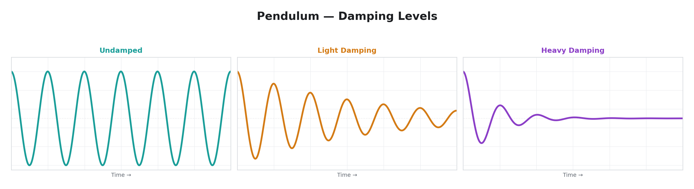
19 — Pendulum
| Parameter | Label | Function |
|---|---|---|
| Time | Length | Pendulum period. Fully counter-clockwise = short pendulum (fast swings). Fully clockwise = long pendulum (slow swings). |
| Space | Gain | Output amplitude. |
| Slope | Damp | Damping coefficient. Fully counter-clockwise = undamped (oscillates forever). Fully clockwise = heavy damping (oscillation dies out quickly). |
Per-line: No
Simulates a damped pendulum — a weight on a string swinging back and forth. A restoring force proportional to displacement from center pulls the pendulum back when it swings to one side. Damping gradually reduces the swing amplitude. The result is a decaying sinusoidal oscillation that feels natural and organic — the kind of motion you see when you push a swing and let it settle.
A MIDI note-on displaces the pendulum to its maximum angle, triggering a new decay — but only when the pendulum has come to rest. Note-on messages received while the pendulum is still swinging are ignored. Without MIDI, the pendulum swings from its initial displacement and either oscillates indefinitely (no damping) or settles to center (with damping).
The difference between Pendulum and a damped Free LFO is in how the motion decays. Pendulum applies a restoring force proportional to displacement and friction proportional to velocity, so the output naturally settles to center. A damped Free LFO fades the waveform in place without pulling toward a rest point.
USB HID Input
These operators use USB-connected human interface devices as modulation sources. Connect a device to the USB Host port to use these operators. See USB HID Devices for connection details, device compatibility, and persistence behavior.
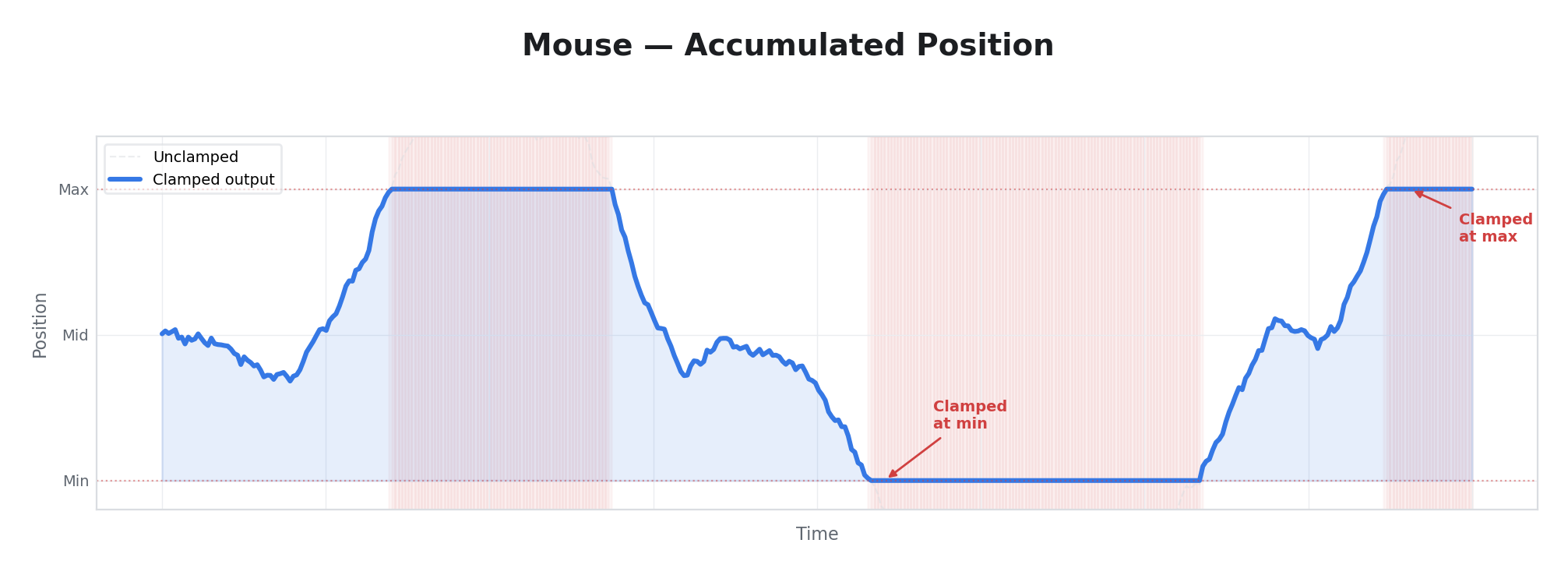
32 — Mouse
| Parameter | Label | Function |
|---|---|---|
| Time | Slew | Smoothing. Fully counter-clockwise = instant response. Fully clockwise = very slow, gliding response. |
| Space | Gain | Output amplitude. |
| Slope | Axis | Selects which mouse axis to read: X position, Y position, Scroll Wheel, or Buttons. |
Per-line: No
Tracks USB mouse movement as an accumulated position. Moving the mouse left/right or up/down sweeps the modulation value across its full range. The position is clamped at both ends, so continuous movement in one direction eventually hits the limit. Reconnecting or switching away does not reset the position — it persists as long as the device is powered.
The Wheel axis accumulates scroll wheel deltas. The Buttons axis provides a gate output — any mouse button press drives the output to maximum.
Approximately two full mouse sweeps cover the entire modulation range. For finer control, increase Slew or reduce Gain. See Mouse in USB HID Devices for connection details and persistence behavior.
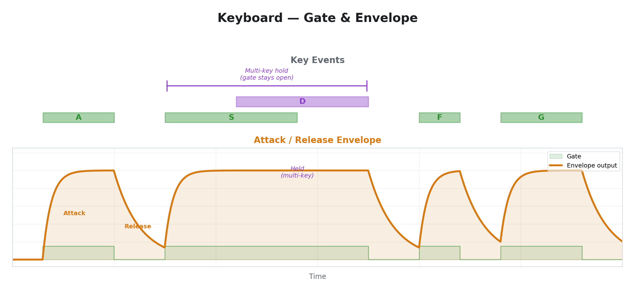
33 — Keyboard
| Parameter | Label | Function |
|---|---|---|
| Time | Attack | Ramp-up rate when a key is pressed. Fully counter-clockwise = instant. Fully clockwise = very slow. |
| Space | Release | Ramp-down rate when all keys are released. Fully counter-clockwise = instant. Fully clockwise = very slow. |
| Slope | Curve | Envelope shape: linear, exponential, or logarithmic. |
Per-line: No
Provides an attack/release envelope triggered by USB keyboard input. Any key press activates the gate. Holding multiple keys keeps the gate active — it only releases when all keys are released. This functions identically to Trigger Env but responds to keyboard input instead of MIDI notes.
With fast Attack and slow Release, a brief keypress produces a percussive burst. With slow Attack and fast Release, keys create a gradual swell that snaps off. The Curve parameter shapes the envelope contour using the same three curves as Trigger Env.
Particularly useful in performance when a MIDI controller is not available — any USB keyboard becomes a modulation trigger surface. See Keyboard in USB HID Devices for key handling details.
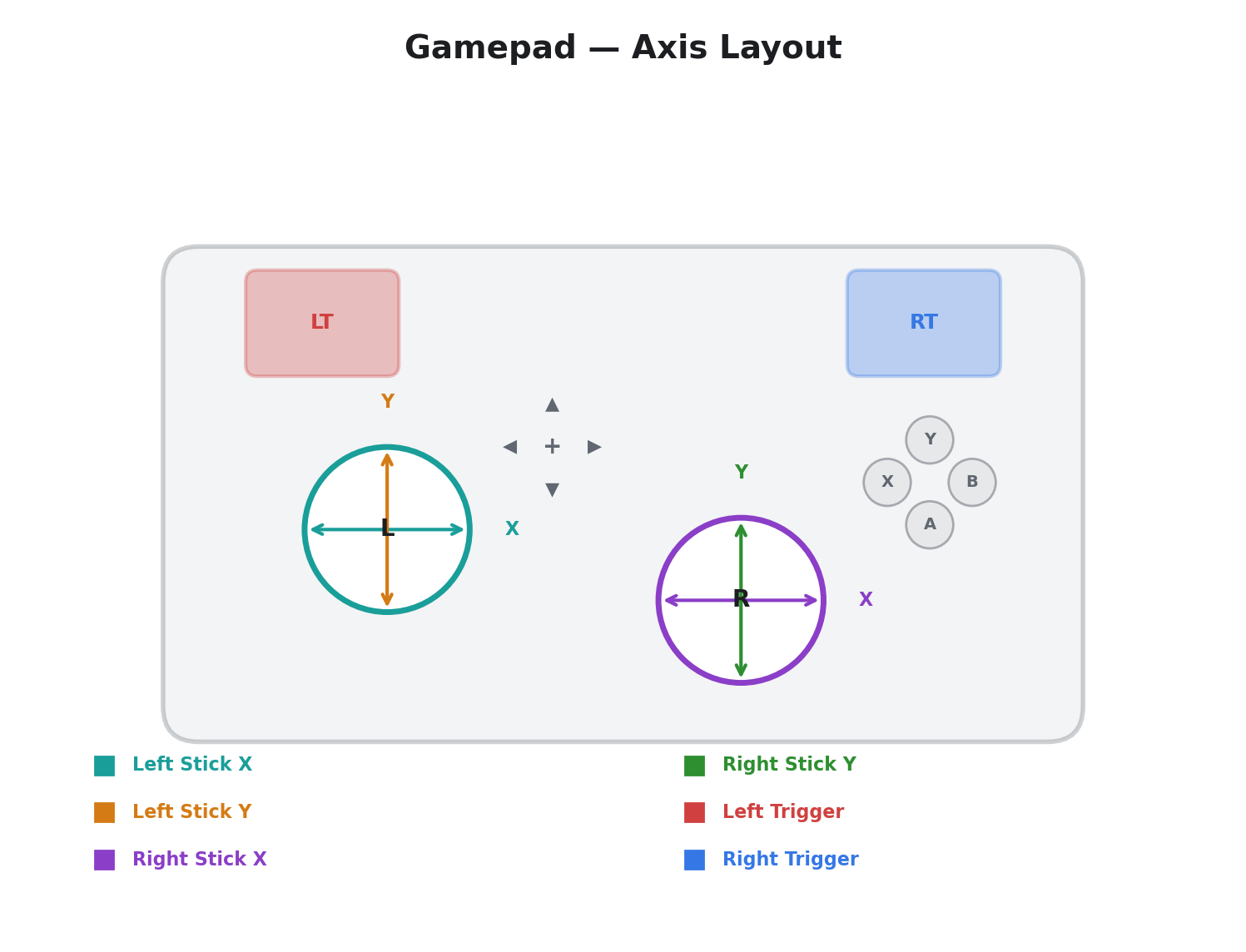
34 — Gamepad
| Parameter | Label | Function |
|---|---|---|
| Time | Slew | Smoothing. Fully counter-clockwise = instant response. Fully clockwise = very slow response. |
| Space | Gain | Output amplitude. |
| Slope | Axis | Selects which gamepad input to read: Left Stick X/Y, Right Stick X/Y, Left/Right Trigger, or Buttons. |
Per-line: No
Reads USB gamepad analog stick axes, triggers, and buttons. The Axis parameter selects from seven inputs: Left Stick X/Y, Right Stick X/Y, Left/Right Trigger, and Buttons (any button gate). Stick axes are spring-centered, returning to the midpoint when released — ideal for temporary parameter offsets. Triggers provide one-directional ramps.
See Gamepad in USB HID Devices for axis details, spring-return behavior, and performance tips.
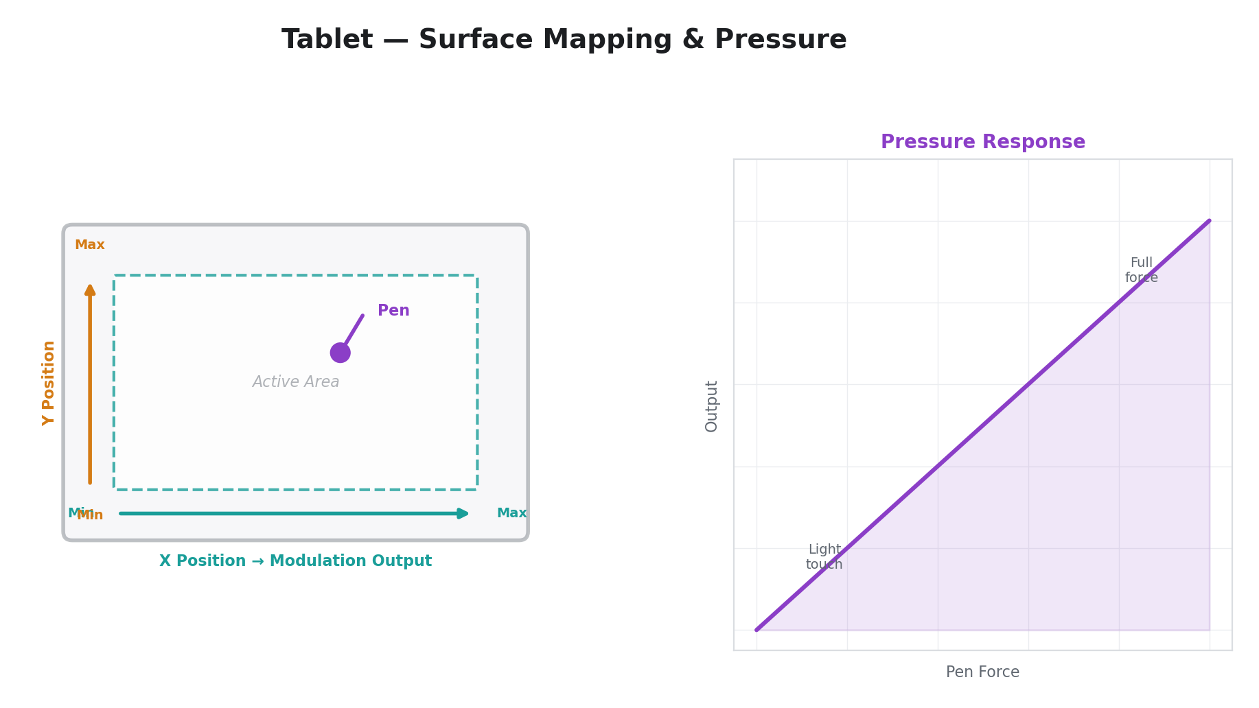
35 — Tablet
| Parameter | Label | Function |
|---|---|---|
| Time | Slew | Smoothing. Fully counter-clockwise = instant response. Fully clockwise = very slow response. |
| Space | Gain | Output amplitude. |
| Slope | Axis | Selects which tablet input to read: X Position, Y Position, Pressure, or Buttons. |
Per-line: No
Reads absolute position, pressure, and button state from USB digitizer devices — drawing tablets, touchscreens, and touchpads. Unlike Mouse (which accumulates relative movement), Tablet maps the device's absolute coordinate space directly to the modulation range. The Axis parameter selects X Position, Y Position, Pressure, or Buttons (tip switch, barrel button, or eraser gate).
Pressure is the key differentiator — pressure-sensitive tablets report continuous pen force, enabling expressive modulation that responds to how hard the performer presses. Coordinates persist when the pen is lifted, freezing the last known position until the pen touches down again.
See Drawing Tablet in USB HID Devices for device compatibility, axis behavior, and touchscreen notes.
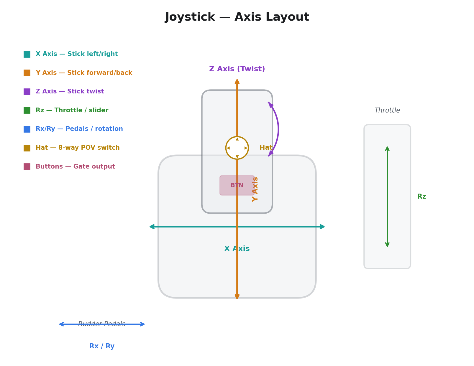
36 — Joystick
| Parameter | Label | Function |
|---|---|---|
| Time | Slew | Smoothing. Fully counter-clockwise = instant response. Fully clockwise = very slow response. |
| Space | Gain | Output amplitude. |
| Slope | Axis | Selects which joystick input to read: X, Y, Z, Rx, Ry, Rz, Hat, or Buttons. |
Per-line: No
Reads USB joystick axes, hat switch, and buttons. The Axis parameter selects from eight inputs: X, Y, Z, Rx, Ry, Rz, Hat, and Buttons. Joysticks typically provide more axes than gamepads — up to six plus a hat switch — suitable for flight sticks, HOTAS setups, throttle quadrants, and rudder pedals.
Unlike Gamepad, axes are often not spring-centered — throttle levers and rudder pedals stay where you set them. The Hat switch maps its eight directional positions across the output range, with the center (released) position producing the midpoint.
See Joystick in USB HID Devices for axis mapping, compatibility notes, and HOTAS tips.
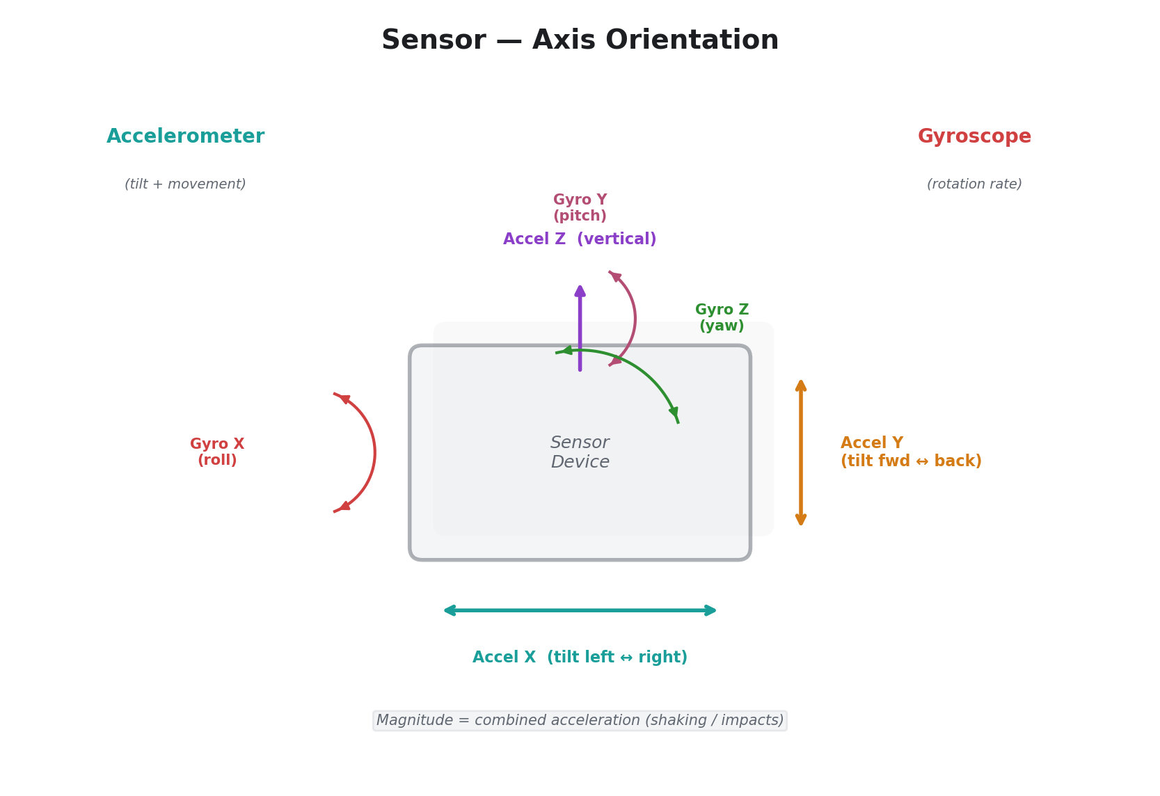
37 — Sensor
| Parameter | Label | Function |
|---|---|---|
| Time | Slew | Smoothing. Fully counter-clockwise = instant response. Fully clockwise = very slow response. |
| Space | Gain | Output amplitude. |
| Slope | Axis | Selects which sensor axis to read: Accel X/Y/Z, Gyro X/Y/Z, or Magnitude. |
Per-line: No
Reads USB sensor devices providing accelerometer and gyroscope data. The Axis parameter selects from seven inputs: Accel X/Y/Z, Gyro X/Y/Z, and Magnitude. Accelerometer axes respond to both static tilt (gravity) and dynamic acceleration (shaking). Gyroscope axes measure rotation rate, returning to the midpoint when rotation stops. Magnitude captures total acceleration regardless of direction.
Sensor data tends to be noisy — increase Slew for smooth modulation, or decrease it for responsive gesture detection.
See Sensor in USB HID Devices for axis orientation, rest positions, and usage tips.
Per-Line Rendering
Six of the 39 operators produce per-scanline varying output. This means the modulation value changes for every horizontal line of the video frame, not just once per field. Per-line rendering enables spatial modulation effects that would be impossible with field-rate updates alone.
| Operator | Per-line function | What varies per line |
|---|---|---|
| CV Input | Reads input at each scanline | Input voltage at that moment in the scan |
| Audio Input | Reads input at each scanline | Audio waveform mapped to vertical position |
| Comparator | Compares input at each scanline | Binary threshold map across frame |
| Ring Mod | Multiplies two input channels per line | Product of two input signals, spatially varying |
| Peak Hold | Combines held peak with per-line input | Spatial floor at the held peak value |
| Quantizer | Quantizes input at each scanline | Staircase-quantized spatial pattern |
Note: H Displace and V Gradient are listed in the operator reference as spatial per-line operators, but they are currently disabled in firmware and produce no per-line output. They are reserved for a future firmware update.
When a per-line operator is active, the parameter is updated once per scanline during active video rather than once per field. This means the top of the frame may have a different value than the bottom.
Audio & CV Inputs
Videomancer has four analog input jacks on the rear panel, labeled Input 1 through Input 4. Each jack accepts control voltages (slow-moving signals used for parameter automation) or audio-rate signals (for waveform-driven and frequency-reactive modulation). There is no hardware distinction between CV and audio — the same jack handles both. The difference is entirely in how the modulation operator processes the signal.
Hardware Overview
Each input is sampled once per video scanline, synchronized to the video timing. The effective sample rate per channel equals the video line rate — approximately 15,700 samples per second at standard definition or 33,750 samples per second at high definition. This is fast enough to capture control voltages with full fidelity and audio signals up to approximately 7.8 kHz (SD) or 16.8 kHz (HD).
Input Channels
Eleven modulation operators read from the analog inputs — CV Input, Audio Input, FFT Band, Envelope, Sample & Hold, Comparator, Ring Mod, Peak Hold, Field Accum, Slew Limiter, and Quantizer. Most of these operators let you select which input channel to read via the Slope knob, with six options:
| Slope Position | Channel | Description |
|---|---|---|
| Far left | Ch 1 | Input jack 1 only |
| Left of center | Ch 2 | Input jack 2 only |
| Center-left | Ch 3 | Input jack 3 only |
| Center-right | Ch 4 | Input jack 4 only |
| Right of center | Ch 1+2 | Average of inputs 1 and 2 |
| Far right | Ch 3+4 | Average of inputs 3 and 4 |
The mixed-pair options (Ch 1+2 and Ch 3+4) are useful when you want a modulation source derived from two related signals — for example, left and right channels of a stereo audio signal.
FFT Band, Field Accum, and Slew Limiter are exceptions — they always read Input 1 regardless of the Slope setting. FFT Band uses Slope to select a display-only band label. Field Accum uses Slope to control leak rate. Slew Limiter uses Slope to control fall rate.
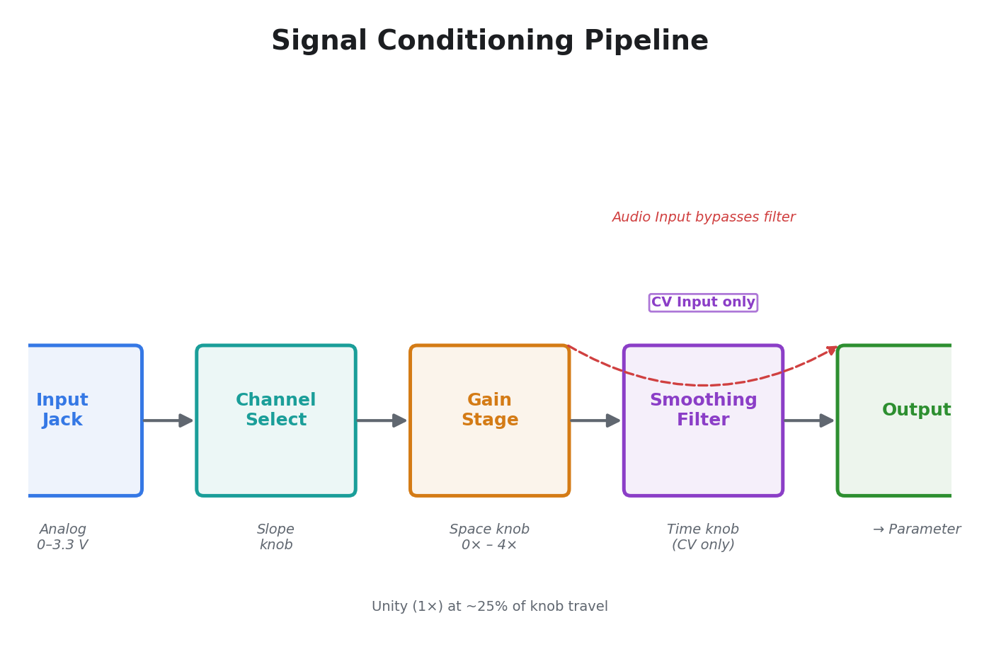
Signal Conditioning
Every input-reading operator processes the analog signal through the same pipeline:
Analog input jack
  │
  ▼
Input signal
  │
  ├─ Smoothing filter (CV Input only)
  │    Rate controlled by Time knob
  │    Counter-clockwise = instant tracking
  │    Clockwise = very slow glide
  │
  ├─ Gain stage (controlled by Space knob)
  │    ~25% of travel = unity (1×)
  │    Maximum = 4× amplification
  │    Output is clamped at both ends
  │
  └─ Final output → parameter output
The gain stage is shared by most input operators. At zero, the output is silent. Unity gain (1×) is at about 25% of the Space knob's travel, and the gain increases linearly to 4× at maximum — useful for boosting quiet input signals to fill the full modulation range. The output is always clamped so amplification cannot cause unexpected results.
The smoothing filter is unique to the CV Input operator. It smooths transitions at a rate controlled by the Time knob, turning abrupt voltage changes into gentle glides. Audio Input bypasses this filter entirely so that audio waveforms pass through unaltered.
Midpoint Convention
Some operators process signals that swing above and below a center point. The center is at half scale — the midpoint of the modulation range. Operators like Envelope and Ring Mod use this center as their reference. If your input signal always stays above zero (for example, a gate or trigger), this convention does not affect normal operation.
Per-Line Spatial Modulation
Six operators support per-line rendering, where the modulation value changes for each scanline of the video frame. Instead of updating once per field, the parameter updates once per scanline. This maps the input signal spatially across the frame — the top of the image can have a different modulation value than the bottom.
Per-line rendering is particularly powerful with audio inputs. Feeding a sine wave into Audio Input in per-line mode maps the instantaneous audio waveform vertically across the frame. Higher frequencies create more visible oscillations in the vertical dimension. This technique produces modulation effects that would be impossible with conventional per-frame updates.
The six per-line operators are: CV Input, Audio Input, Comparator, Ring Mod, Peak Hold, and Quantizer.
Frequency Analysis (FFT Bands)
Note: The FFT Band operator does not currently perform frequency-selective analysis. In the current firmware, it reads broadband energy from Input 1 (rectified envelope) and tracks it with a smoothing filter. The Slope knob's "Band" label is display-only and does not change the audio processing. All band selections produce the same output — a broadband energy follower on Input 1.
To achieve frequency-selective audio reactivity with the current firmware, apply external bandpass filtering (via a hardware filter or mixer EQ) before the input jack, and assign separate filtered signals to different input channels using the Envelope or CV Input operators.
MIDI
Videomancer receives and processes MIDI over three independent ports: a rear-panel TRS jack, a rear-panel USB Host connector, and a front-panel USB Device connector. All three ports feed the same message-handling pipeline — any CC, note, clock, or program change message is processed identically regardless of which port it arrives on. You do not need to choose which port is "active" — all three are always listening.
MIDI Ports
TRS MIDI (DIN)
The rear panel has a TRS MIDI In jack (3.5mm) using the Type A pinout (MIDI Manufacturers Association standard). This is the connection to use with hardware MIDI gear — Eurorack MIDI-to-CV modules, drum machines, hardware sequencers, and any device with a 5-pin DIN MIDI output.
How to use it:
- Connect a MIDI source to the TRS MIDI In jack on the rear panel using a TRS-A cable or a TRS-A to 5-pin DIN adapter.
- MIDI messages are received immediately — no configuration required.
TRS-A pinout: Videomancer uses the MIDI Manufacturers Association standard (TRS-A). If your source device uses TRS-B (used by some Korg and Arturia products), you need a TRS-A-to-B adapter cable.
TRS MIDI Out: The rear panel also has a TRS MIDI Out jack. This output is reserved for future use — no MIDI data is currently transmitted from this jack.
USB MIDI Host (Controller Input)
The rear-panel USB Host port (USB-C connector) accepts USB MIDI controllers — keyboards, knob boxes, pad controllers, and any other class-compliant USB MIDI device. Videomancer acts as the USB host, providing power and recognizing the connected device automatically.
How to use it:
- Plug a USB MIDI controller into the USB Host port on the rear panel.
- The controller is recognized automatically — no configuration or driver installation required.
- Send MIDI CC messages from the controller to modulate Videomancer's parameters.
Any class-compliant USB MIDI device works. Common examples include Novation Launch Control, Korg nanoKONTROL, Arturia MiniLab, Akai MPK Mini, and generic USB MIDI keyboards. Devices that require vendor-specific drivers (non-class-compliant) are not supported.
The USB Host port also accepts USB HID devices (mice, keyboards, gamepads) — see USB HID Devices. If a device provides both MIDI and HID interfaces (uncommon), both are active simultaneously. A USB hub can be used to connect multiple devices to the single host port.
USB MIDI Device (Computer Connection)
The front-panel USB Device port (USB-C connector, also used for firmware updates) allows a computer to send MIDI to Videomancer. When connected to a computer via USB, Videomancer appears as a class-compliant USB MIDI device — no driver installation is needed on macOS, Windows, or Linux. The device name appears in your DAW or MIDI software's device list.
How to use it:
- Connect Videomancer to your computer with a USB-C cable.
- Videomancer appears as a MIDI device in your DAW, Max/MSP, TouchDesigner, or other MIDI software.
- Send MIDI CC, notes, clock, or program change messages from the software.
Supported Messages
All three MIDI ports support the same set of standard MIDI messages:
| Category | Messages |
|---|---|
| Channel Voice | Note On, Note Off, Control Change, Program Change, Pitch Bend, Polyphonic Aftertouch, Channel Pressure |
| System Common | MTC Quarter Frame, Song Position Pointer, Song Select, Tune Request |
| System Real-Time | Clock, Start, Continue, Stop, Active Sensing, System Reset |
| System Exclusive | SysEx (up to 64 bytes) |
All standard MIDI behaviors are supported, including interpreting Note On with velocity 0 as Note Off.
MIDI CC Mapping
MIDI Continuous Controller (CC) messages are the primary way to remotely control Videomancer's modulation parameters. Each of the 12 modulator channels (P1–P12) can be assigned a CC number. When a MIDI CC message arrives with that number, its value is applied as a modulation offset on that channel.
Default CC Assignments
Out of the box, the CC assignments are:
| Modulator | CC MSB | CC LSB | Control |
|---|---|---|---|
| P1 (Knob 1) | CC 0 | CC 32 | Rotary knob 1 |
| P2 (Knob 2) | CC 1 | CC 33 | Rotary knob 2 |
| P3 (Knob 3) | CC 2 | CC 34 | Rotary knob 3 |
| P4 (Knob 4) | CC 3 | CC 35 | Rotary knob 4 |
| P5 (Knob 5) | CC 4 | CC 36 | Rotary knob 5 |
| P6 (Knob 6) | CC 5 | CC 37 | Rotary knob 6 |
| P7 (Toggle 7) | CC 6 | CC 38 | Toggle switch 7 |
| P8 (Toggle 8) | CC 7 | CC 39 | Toggle switch 8 |
| P9 (Toggle 9) | CC 8 | CC 40 | Toggle switch 9 |
| P10 (Toggle 10) | CC 9 | CC 41 | Toggle switch 10 |
| P11 (Toggle 11) | CC 10 | CC 42 | Toggle switch 11 |
| P12 (Fader) | CC 11 | CC 43 | Linear fader 12 |
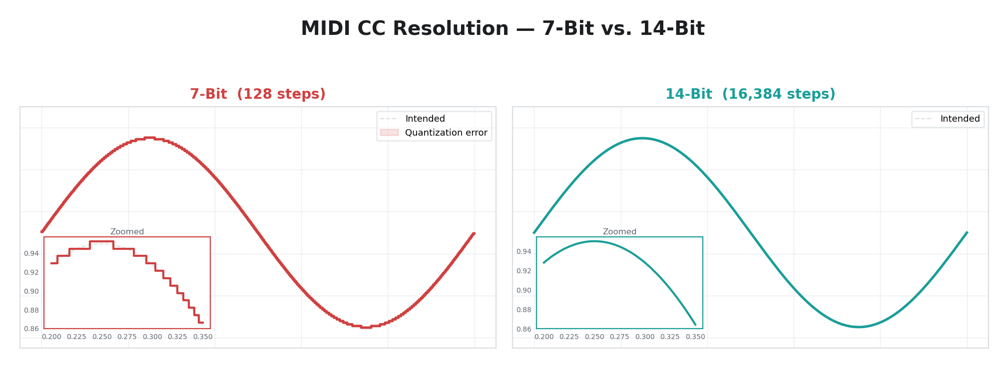
14-Bit Resolution
Each assignment supports optional 14-bit high-resolution CC for smoother control. The MSB CC provides coarse control. If a paired LSB CC is also assigned, it adds fine resolution for smooth, jitter-free transitions across the full range. By default, the LSB is auto-paired at MSB + 32 (the MIDI standard convention for 14-bit CC pairs). Sending only the MSB is fine for most uses — the LSB is optional.
One CC, One Modulator
Each CC number can be assigned to exactly one modulator. If you assign a CC that is already mapped to another modulator, the old assignment is automatically cleared. This prevents ambiguous routing.
Persistence
CC assignments are saved to flash memory and restored on power-up. They are also stored per-preset, so different presets can use different CC layouts — useful when switching between different MIDI controllers or performance setups.
MIDI Assign
MIDI Assign provides an intuitive way to assign CC numbers without memorizing CC tables. You can either point at a modulator and wiggle a knob on your MIDI controller — on any MIDI port (TRS, USB Host, or USB Device) — or use the rotary encoder to manually dial in a CC number. The assignment is saved immediately and restored on power-up.
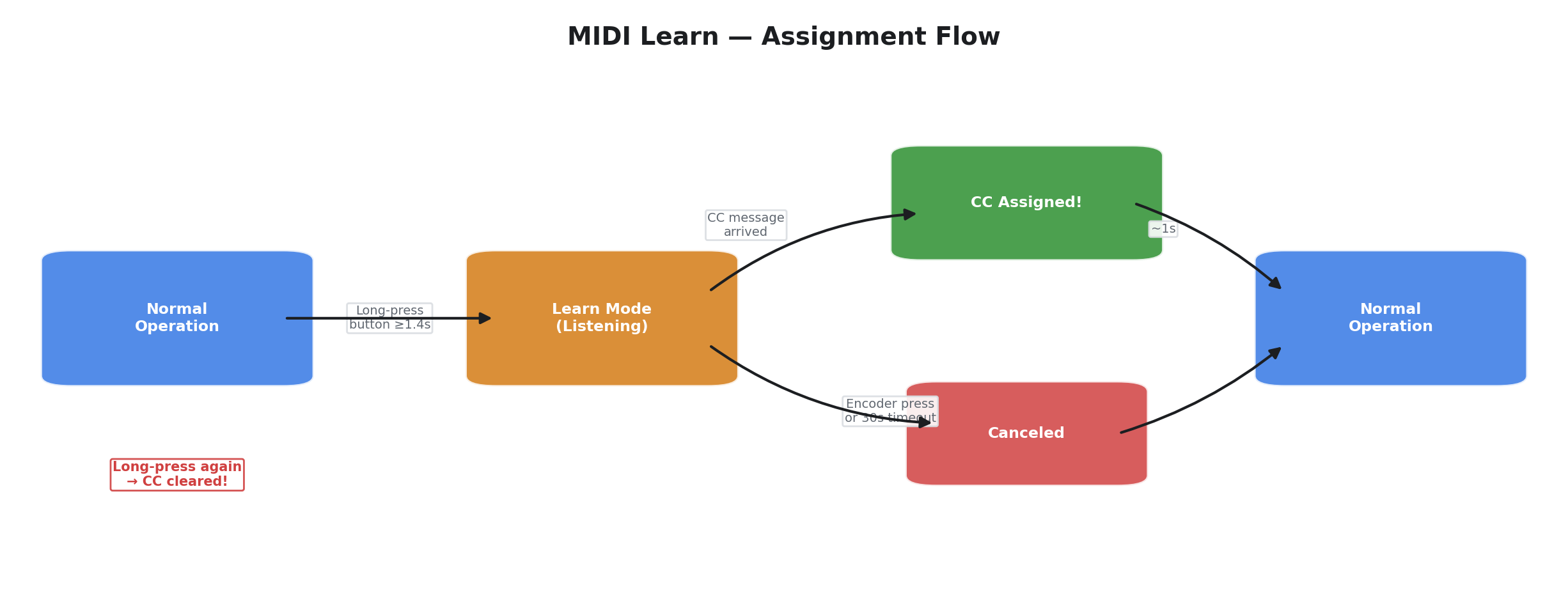
Entering Assign Mode
- Navigate to the modulator you want to assign (P1 through P12) so its screen is visible.
- Long-press its button — hold for at least 1.4 seconds. A short press cycles through modulator pages as usual; assign mode only activates on a long press.
- The LCD switches to assign mode:
P3  MIDI Assign
Move a CC..._
The blinking cursor (_) on the bottom line pulses at about 2 Hz to show the system is listening. The LED for the target modulator also blinks at 2 Hz so you can tell at a glance which modulator is waiting for input.
Assigning a CC (Automatic)
- Move any knob, fader, or button on your MIDI controller. The first CC message received is captured — it does not matter which MIDI port the message arrives on (TRS, USB Host, or USB Device). Only CC-type messages are candidates; notes, pitch bend, program change, and other message types are ignored.
- The LCD briefly confirms the assignment:
P3  MIDI Assign
CC 74 assigned!
After about one second the display returns to the normal modulator view and the assignment is persisted to flash.
If a MIDI controller sends a rapid burst of CC values (for example, quickly moving an expression pedal), only the first CC number in the burst is captured. Once a CC number has been accepted, the assign session is complete — additional CC messages with the same or different numbers are not captured.
Assigning a CC (Manual)
Instead of wiggling a physical MIDI knob, you can also select a CC number manually:
- Rotate the encoder clockwise or counter-clockwise to select a CC number (0–127). The display updates to show the pending CC number:
P3  MIDI Assign
CC# 74_
- Press the encoder button to confirm the selection. The display shows:
P3  MIDI Assign
CC 74 assigned!
After about one second the display returns to the normal modulator view and the assignment is persisted to flash. The CC number wraps around — turning past 127 returns to 0, and turning below 0 returns to 127.
If a MIDI CC arrives while you are dialing in a number with the encoder, the incoming CC takes priority and the manual selection is discarded.
14-Bit Auto-Pairing
When a CC is learned, the MSB → LSB pair is set automatically following the MIDI standard: the LSB CC number equals MSB + 32. For example, learning CC 14 auto-pairs LSB CC 46.
CCs in the range 32–63 are already defined as LSB positions by the MIDI specification. If you assign a CC with an MSB number of 32 or higher, no LSB auto-pair is created because there is no valid partner — the assignment operates at 7-bit resolution only. For full 14-bit control, use MSB CC numbers 0–31.
Canceling Assign Mode
- Press the encoder when no CC# has been dialed in (i.e., the encoder has not been turned) to cancel without making a change. The display returns to the normal modulator view and the existing CC assignment (if any) is left untouched. If a CC# has been dialed in via the encoder, pressing the button confirms the selection instead of canceling. To cancel with a pending CC# showing, long-press the same modulator button again.
Clearing an Assignment
- Long-press the same modulator button while it already has a learned CC assignment. The LCD shows "CC cleared!" for about one second, then returns to normal operation. The modulator reverts to its default CC assignment from the factory table.
CC Conflicts
Each CC number can be assigned to exactly one modulator. If you learn a CC that is already mapped to a different modulator, the new assignment wins and the old modulator's mapping is automatically cleared — there is no conflict warning. This one-to-one rule keeps routing unambiguous.
Channel Filtering
MIDI Assign respects the active MIDI channel filter. If you have set channel filtering to a specific channel, only CCs arriving on that channel are candidates for learning. In omni mode (the default), CCs on any channel are accepted. This prevents accidental learning from other devices sharing the same MIDI bus.
Viewing Existing Assignments
When the modulator screen is showing the Source parameter page for a modulator that has a CC assignment, the display shows the assigned CC number:
P1  Free LFO
Source   CC:074
This lets you check which CC is mapped without entering assign mode.
Persistence and Presets
Learned CC assignments follow the same persistence rules as manual assignments — saved to flash and stored per-preset. Loading a different preset via the front panel or via MIDI Program Change restores that preset's CC layout.
A power cycle during assign mode is harmless — assign mode is a temporary UI state. If power is lost while assign mode is active, Videomancer boots normally with the last saved CC map intact.
Summary of Assign Mode Interactions
| User Action | System Response |
|---|---|
| Short-press Px | Normal: cycles modulator parameter page |
| Long-press Px (≥1.4 s), no existing CC | Enters assign mode (LCD + LED blink) |
| Long-press Px (≥1.4 s), CC already assigned | Clears the assignment, shows "CC cleared!" |
| Move MIDI knob during assign (any port) | Captures CC, shows "CC N assigned!", persists |
| Rotate encoder during assign | Selects CC# manually (0–127, wrapping) |
| Press encoder (CC# dialed in) | Confirms manual CC# selection, persists |
| Press encoder (no CC# dialed in) | Cancels assign mode, no change |
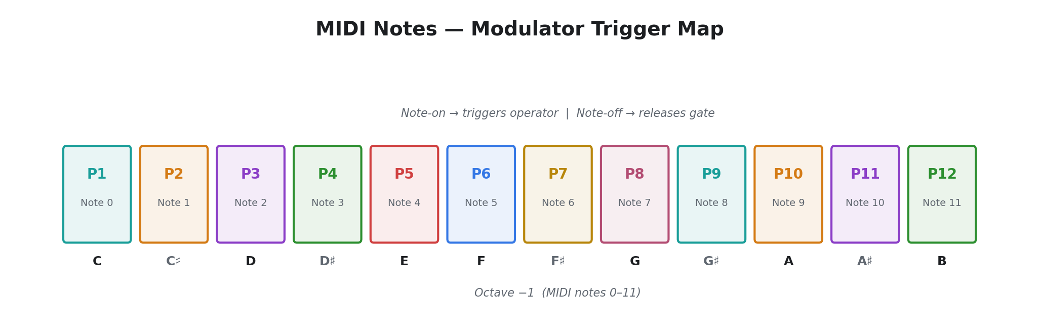
MIDI Notes
MIDI note messages provide trigger control for modulation operators that respond to gates — Trigger Env, Bouncing Ball, Pendulum, and MIDI Turing.
Note-to-modulator mapping: Note numbers 0 through 11 map directly to modulators P1 through P12. Note 0 triggers P1, note 1 triggers P2, and so on. Notes 12 and above are ignored.
| Note Number | Modulator | Octave (Middle C = 60) |
|---|---|---|
| 0 (C-2) | P1 | Lowest C |
| 1 (C#-2) | P2 | |
| 2 (D-2) | P3 | |
| 3 (D#-2) | P4 | |
| 4 (E-2) | P5 | |
| 5 (F-2) | P6 | |
| 6 (F#-2) | P7 | |
| 7 (G-2) | P8 | |
| 8 (G#-2) | P9 | |
| 9 (A-2) | P10 | |
| 10 (A#-2) | P11 | |
| 11 (B-2) | P12 |
Note On activates the target modulator. Operators that respond to notes — like Trigger Env — begin their attack phase. Bouncing Ball resets to the top and starts a new drop. MIDI Turing advances one step in its shift register sequence.
Note Off (or Note On with velocity 0) releases the modulator, triggering the release phase of Trigger Env or allowing Pendulum to decay naturally.
Practical tip: Most MIDI keyboards default to middle C (note 60). To trigger Videomancer's modulators, you need to play in the lowest octave range of your keyboard (notes 0–11), or use your DAW to transpose MIDI data down. Many DAWs allow you to set a MIDI note offset, or you can use a MIDI monitor to verify you are sending the correct note numbers.
MIDI Program Change
MIDI Program Change messages recall presets. The program number (0–127) maps directly to a preset slot. When a Program Change message is received, Videomancer loads the corresponding preset — restoring all modulator settings, FPGA program selection, and CC assignments stored in that preset.
This allows a MIDI sequencer or foot controller to switch between Videomancer configurations during a performance.
MIDI Clock & Transport
Videomancer synchronizes its internal transport to external MIDI clock, enabling tempo-locked modulation via the Sync LFO, Motion LFO, and Clock Div operators.
Clock Synchronization
MIDI Clock messages arrive at 24 pulses per quarter note (24 PPQN). Videomancer measures the time interval between consecutive beats (every 24 clock ticks) and derives the BPM. The derived BPM updates continuously as long as clock messages are being received, so tempo changes in the master are tracked in real time.
The BPM is displayed on the LCD and used by all transport-locked operators. No manual BPM entry is needed when an external clock is connected — Videomancer follows the master automatically.
Transport Control
Three MIDI messages control the transport state:
| Message | Action |
|---|---|
| Start | Begins playback from the start. The transport position resets to zero. |
| Continue | Resumes playback from the current position. |
| Stop | Stops playback. BPM continues to be tracked from incoming clock messages. |
Transport state affects different operators differently:
- Free LFO and most operators produce no modulation output while the transport is stopped. Free LFO resets its phase to zero on stop.
- Sync LFO advances only while playing. Its output drops to zero when stopped and freezes when paused.
- Motion LFO reads the transport phase directly. It jumps to the correct position when playback starts.
- Clock Div produces gates derived from the transport phase. It stops gating when the transport stops.
- CV Input and Audio Input are the exceptions — they run regardless of transport state.
MIDI Time Code (MTC)
Videomancer also supports MIDI Time Code for absolute timecode synchronization. MTC messages are assembled into complete timecode positions (hours:minutes:seconds:frames), supporting 24, 25, 29.97 (drop-frame), and 30 fps frame rates. When playing with MTC, the transport follows the timecode position rather than clock pulses.
Tap Tempo
When no MIDI clock is connected, the BPM can be set manually via tap tempo. Tapping the transport button at regular intervals sets the BPM based on a rolling average of the last four tap intervals. There is a 3-second timeout — if you stop tapping for more than 3 seconds, the next tap starts a fresh measurement.
LED Feedback
The transport LEDs reflect the current state:
| State | Stop LED | Play LED |
|---|---|---|
| Stopped | Solid on | Off |
| Playing | Off | Solid on |
| Paused | Off | Blinking |
MIDI Channel Filtering
All MIDI input can be filtered by channel:
| Setting | Behavior |
|---|---|
| Disabled | No MIDI messages are processed |
| Omni (default) | Messages on all 16 MIDI channels are accepted |
| Channel 1–16 | Only messages on the selected channel are accepted |
The channel filter applies to CC, note, program change, and aftertouch messages. System messages (clock, start, stop, continue, SysEx) are always accepted regardless of the channel filter setting, since they have no channel.
The channel filter is set in the Settings menu and persists across power cycles.
USB HID Devices
Videomancer's USB Host port accepts standard USB Human Interface Devices — mice, keyboards, gamepads, drawing tablets, joysticks, and sensors. These devices provide expressive, gestural modulation sources that are familiar and intuitive. Any class-compliant USB HID device works without drivers or configuration.
Supported Device Types
| Device Type | Input Style | Typical Use |
|---|---|---|
| Mouse | Accumulated relative position | Sweep parameters by dragging |
| Keyboard | Gate (any key pressed) | Trigger envelopes and gates |
| Gamepad | Analog sticks, triggers, buttons | Two-axis control, spring-return |
| Drawing Tablet | Absolute position, pressure | Pressure-expressive gestural control |
| Joystick | Up to 6 axes, hat switch, buttons | Multi-axis flight stick, HOTAS, throttle |
| Sensor | Accelerometer, gyroscope | Motion-controlled tilt/shake modulation |
Connecting Devices
Plug the USB device into the USB Host port (USB-C, rear panel). The device is recognized automatically within a few seconds. Up to four HID devices can be connected simultaneously using a USB hub — for example, a mouse and a gamepad, or a keyboard and a drawing tablet.
When a device is connected, the LCD briefly indicates the connection. If the current modulator is set to a matching HID operator (Mouse, Keyboard, Gamepad, Tablet, Joystick, or Sensor), input begins immediately.
HID state is persistent — the accumulated mouse position, keyboard gate, gamepad axes, and tablet coordinates are maintained even when you switch the modulator to a different operator and back. Disconnecting a device freezes the last known state. Reconnecting does not reset values — the previous state persists until the next power cycle.
Mouse
Any standard USB mouse works, including wireless mice with USB receivers. The mouse provides four modulation axes selectable via the Slope knob on the Mouse operator (operator 32):
| Axis | Behavior |
|---|---|
| X position | Accumulated horizontal movement (starts at center) |
| Y position | Accumulated vertical movement (starts at center) |
| Scroll wheel | Accumulated scroll movement (starts at center) |
| Buttons | Gate: any button pressed |
Mouse movement is relative — the mouse reports how far it moved since the last report, and Videomancer accumulates those movements into a bounded position. Moving left decreases X; moving right increases it. The position starts at center and clamps at both extremes, so continuous movement in one direction eventually hits the limit.
Approximately two full mouse sweeps cover the entire modulation range. For finer control, increase the Slew parameter or reduce Gain. For bolder sweeps, increase Gain.
The mouse position persists across device reconnections and modulator changes. It does not reset when you unplug and replug the mouse — only a full power cycle returns it to center.
Keyboard
Any standard USB keyboard works. The Keyboard operator (operator 33) provides an attack/release envelope triggered by key presses — any key activates the gate. Multiple simultaneous key presses keep the gate held; it only releases when all keys are released.
The key count (how many keys are currently pressed) is tracked. This means holding three keys and releasing one does not trigger a false release — the gate stays active until the last key is lifted.
The three operator parameters control the envelope shape:
| Parameter | Function |
|---|---|
| Time (Attack) | How fast the output ramps up when a key is pressed. Fully counter-clockwise = instant snap to maximum. Fully clockwise = very slow swell. |
| Space (Release) | How fast the output ramps down when all keys are released. Fully counter-clockwise = instant cut. Fully clockwise = long decay. |
| Slope (Curve) | Envelope contour: linear (equal rate throughout), exponential (fast start, slow finish), or logarithmic (slow start, fast finish). |
Keyboard modulation is useful when a MIDI controller is not available. Any USB keyboard becomes a modulation trigger surface — press keys for percussive hits, hold keys for sustained effects, or tap rhythmically for gated patterns.
Modifier keys (Shift, Ctrl, Alt) count as keys and activate the gate like any other key. There is no difference between letter keys, number keys, and modifier keys for modulation purposes.
Gamepad
Standard USB gamepads (Xbox-compatible, PlayStation-compatible, and generic HID gamepads) are supported. The Gamepad operator (operator 34) provides seven selectable inputs:
| Input | Behavior | Rest Position |
|---|---|---|
| Left Stick X | Horizontal axis, spring-centered | Center |
| Left Stick Y | Vertical axis, spring-centered | Center |
| Right Stick X | Horizontal axis, spring-centered | Center |
| Right Stick Y | Vertical axis, spring-centered | Center |
| Left Trigger | Linear pull, no spring return | Minimum (released) |
| Right Trigger | Linear pull, no spring return | Minimum (released) |
| Buttons | Gate: any button pressed | Off (released) |
Analog sticks are spring-centered — they naturally return to the midpoint when released. This makes them ideal for temporary parameter offsets. Push the stick to modulate, release to snap back. Triggers are one-directional ramps suitable for intensity control.
The D-pad / hat switch is not directly exposed as a modulation axis. Buttons are aggregated — any button press on the gamepad drives the Buttons axis high.
Live performance tip: Assign the left stick X and Y to two different parameters for intuitive two-axis control. Use a trigger for a third parameter (intensity or depth). The spring-return behavior means you can make dramatic parameter sweeps and always return to a known position by releasing the stick.
Drawing Tablet
USB drawing tablets and digitizers (Wacom, Huion, XP-Pen, and most USB digitizer devices) provide pressure-sensitive, absolute-position input. The Tablet operator (operator 35) exposes four axes:
| Axis | Behavior |
|---|---|
| X position | Absolute horizontal position on the tablet surface (left edge to right edge) |
| Y position | Absolute vertical position on the tablet surface (top edge to bottom edge) |
| Pressure | Pen or finger pressure (no contact to maximum) |
| Buttons | Gate: tip switch, barrel button, or eraser |
Unlike the Mouse, the Tablet uses absolute positioning — the pen's position on the tablet maps directly to a fixed modulation value. Moving to the left edge always produces the same value; the right edge always produces the opposite extreme. This provides repeatable, deterministic control — the same physical position always produces the same modulation value.
Pressure is the key differentiator from all other input devices. Pressure-sensitive tablets report continuous pen pressure, enabling expressive modulation that responds to how hard you press. Light touches produce subtle modulation; pressing firmly drives the output to maximum. This is particularly natural for musicians and visual artists who are accustomed to pressure-sensitive tools.
Tablet coordinates persist when the pen is lifted — the last known position is held until the pen touches down again. Combined with Slew smoothing (via the Time knob), this creates gestural modulation with natural decay: move the pen to a position, lift, and watch the modulation glide smoothly to a rest state.
The Buttons axis provides a gate output. The tip switch (pen contact with the tablet surface), barrel button (pen side button), and eraser (pen flip) all activate the gate — any contact drives the output high.
Touchscreen note: Some touchscreen devices report as digitizers. If your touchscreen is recognized as a tablet device, it will work with the Tablet operator, though pressure sensitivity depends on the hardware's capabilities.
Joystick
USB flight sticks, HOTAS throttles, and other multi-axis joystick controllers are supported. The Joystick operator (operator 36) is distinguished from the Gamepad operator by how the device identifies itself — devices that report as joysticks are routed here, while devices that report as gamepads use the Gamepad operator.
| Axis | Behavior | Typical Physical Control |
|---|---|---|
| X | Primary stick horizontal | Stick left/right |
| Y | Primary stick vertical | Stick forward/back |
| Z | Third axis | Throttle lever or stick twist |
| Rx | Rotation X | Secondary axis or pedals |
| Ry | Rotation Y | Secondary axis |
| Rz | Rotation Z | Rudder pedals or stick twist |
| Hat | 8-directional switch | POV hat on stick top |
| Buttons | Gate: any button pressed | Stick buttons, hat press |
Joystick axes are typically not spring-centered — throttle levers and rudder pedals stay where you set them, providing absolute positioning similar to the Tablet operator but with more axes. The 8-position hat switch is mapped across the output range: each position corresponds to a different output value, and the center position (hat released) produces the midpoint.
The Joystick operator is ideal for live performance setups where a musician wants dedicated physical controls with independent axes. A HOTAS setup provides throttle on Z, stick on X/Y, and rudder on Rz — four independent modulation sources from a single USB device.
Compatibility note: Not all joystick devices identify themselves the same way. Some USB flight sticks report as gamepads and will be handled by the Gamepad operator instead. If your joystick does not respond under the Joystick operator, try the Gamepad operator.
Sensor
USB sensor devices (motion sensor dongles and similar controllers) provide accelerometer and gyroscope data for motion-controlled modulation. The Sensor operator (operator 37) exposes six axes plus a combined magnitude:
| Axis | Measures | Rest Position |
|---|---|---|
| Accel X | Tilt left/right (gravity component) | Level |
| Accel Y | Tilt forward/back (gravity component) | Level |
| Accel Z | Vertical acceleration (gravity) | Offset by gravity |
| Gyro X | Roll rotation rate | Stationary |
| Gyro Y | Pitch rotation rate | Stationary |
| Gyro Z | Yaw rotation rate | Stationary |
| Magnitude | Combined acceleration magnitude | Varies with orientation |
Accelerometer axes respond to both static tilt (gravity) and dynamic acceleration (shaking, striking). Tilting the sensor slowly produces a smooth modulation sweep — ideal for gradual parameter changes controlled by physical orientation. Shaking the sensor produces rapid, noisy output — useful for percussive or chaotic effects.
Gyroscope axes measure rotation rate, not absolute angle. Spinning the sensor around an axis produces proportional output; when rotation stops, the output returns to the midpoint. This makes gyro axes self-centering like gamepad sticks, suitable for temporary modulation offsets.
The Magnitude axis provides an orientation-independent measure of total acceleration. It responds to shaking, striking, and sudden movements regardless of which direction they occur in. Higher Slew settings smooth the output into a gentle envelope; lower Slew settings capture individual impacts.
Noise note: Sensor data is inherently noisier than other HID inputs. Increase the Slew parameter for smooth, musical modulation. The Gain parameter can reduce noisy signals to a usable range.
Guided Exercises
These exercises progress from basic oscillator modulation through external input processing to generative composition. Each builds on concepts from the previous exercise.
Exercise 1: First Movement
Objective: Understand what modulation does by watching a single LFO move a single parameter.
- Load any FPGA program with a clearly visible effect on Knob 1 (Bitcullis's Hori Decimate or Lumarian's Contrast work well).
- Set modulator P1 to Free LFO. Set Rate to about 40% (a few seconds per cycle). Set Depth to maximum. Set Wave to triangle.
- Watch the FPGA program's parameter sweep smoothly back and forth. The knob position sets the center of the sweep; depth controls how far it swings.
- Slowly decrease Depth. The sweep narrows. At zero, the modulation disappears.
- Change Wave from triangle to square. The parameter now snaps between two values instead of sweeping.
- Try each waveshape. Notice how each produces a different feel of motion from the same rate and depth settings.
Key concepts: Rate controls speed, Depth controls swing range, Wave controls the shape of the motion.
Exercise 2: Audio-Reactive Modulation
Objective: Use an external audio signal to drive parameter changes.
- Connect an audio source to Videomancer's Input 1.
- Set a modulator to FFT Band. Set Gain to maximum. Set Slew to about 30% for gentle smoothing.
- Play music with a strong bass line. Watch the modulated parameter pulse in time with the audio energy.
- Now set a second modulator to Envelope on a different parameter. Set Attack to about 20% and Release to 60%. Compare how the envelope follower tracks the audio versus FFT Band — both respond to overall loudness, but with different smoothing characteristics.
- For true frequency-selective reactivity, apply external bandpass filtering before the input jack — route bass-filtered audio to Input 1 and treble-filtered audio to Input 2, then use separate CV Input or Envelope operators on each channel.
Key concepts: FFT Band tracks broadband audio energy on Input 1, Envelope tracks overall amplitude with configurable attack/release, external filtering enables frequency-selective multi-band reactivity.
Exercise 3: Generative Rhythms
Objective: Combine pattern generators for evolving, non-repeating modulation.
- Set the global BPM to 120 (or connect a MIDI clock).
- Set modulator P1 to Euclidean Rhythm. Rate at about 50% (moderate tempo). Density at about 40% (about 6 pulses in 16 steps). This creates a rhythmic gate pattern.
- Set modulator P2 to Prob Gate. Rate at about 60%. Prob at 50%. Length at about 40%. This creates a second rhythmic pattern that is similar in rate but randomly varies from cycle to cycle.
- Set modulator P3 to Turing Machine. Rate matching the others. Gain at maximum. Mutate at about 20%. This adds a quasi-periodic melodic contour that slowly evolves.
- Let all three run. The Euclidean rhythm provides a steady structural pulse. The Prob Gate adds unpredictable variation. The Turing Machine creates slowly evolving melodic movement. Together, they produce modulation that has rhythmic structure but never exactly repeats.
- Slowly increase the Turing Machine's Mutate parameter. Watch the melodic pattern dissolve from structured repetition into randomness.
Key concepts: Layering different generator types creates complexity, deterministic patterns provide structure, probabilistic elements prevent exact repetition.
Exercise 4: Physics and Chaos
Objective: Explore how physics simulations and mathematical chaos differ from traditional oscillators.
- Set a modulator to Bouncing Ball. Gravity at about 50%, Bounce at about 80%.
- If MIDI is connected, press a key. The ball drops, bounces, and settles. Each key press restarts the drop.
- Now switch to Pendulum. Length at 50%, Damp at about 30%. The parameter swings back and forth, gradually settling to center.
- Switch to Logistic Map. Rate at about 40%. Start with Chaos fully counter-clockwise (stable). Slowly turn Chaos clockwise. Watch the output transition from a steady value, to alternating between two values, to four values, and finally to unpredictable chaos.
- Switch to Cellular (Rule 30). Set Rate to about 30% so you can see individual generations. Watch the apparently random output emerge from a simple three-neighbor rule.
- Change to Rule 90. Notice the more structured, self-similar pattern.
Key concepts: Physics simulations produce natural-feeling decay and oscillation, chaos systems produce deterministic but unpredictable output, the transition from order to chaos is continuous and controllable.
Tips
- Start with Free LFO. It is the simplest operator and the best way to learn what a modulator does to any given FPGA parameter. Once you understand the effect, switch to more complex operators.
- Boolean mode for toggles. When modulating a toggle switch, the modulator outputs 0 or 1. Any operator that produces values crossing the midpoint creates rhythmic toggling — a triangle LFO becomes an alternating on/off pattern.
- Layer slow and fast. Combine a slow modulator (Drift or Perlin Noise at low speed) with a fast one (Free LFO or Euclidean Rhythm). The slow operator creates gradual evolution while the fast one adds rhythmic detail.
- Motion LFO vs. Sync LFO. Use Motion LFO when you need guaranteed phase lock to the transport. Use Sync LFO when BPM-relative speed is sufficient and exact phase alignment is not critical.
- Depth is your friend. If a modulated effect is too dramatic, reduce Depth before changing anything else. Most operators produce useful results across their full parameter range — the issue is usually amplitude, not the operator itself.
- Per-line operators for spatial effects. Any of the six per-line operators can create spatial variation across the frame. CV Input with a ramp or triangle wave on the input produces a clean vertical gradient controlled by the external signal.
- MIDI triggers. Trigger Env, Bouncing Ball, Pendulum, and MIDI Turing all respond to MIDI note messages. Connect a keyboard or sequencer to create musically timed one-shot events.
- Chaos is a spectrum. Logistic Map's Chaos parameter and Turing Machine's Mutate parameter both control the balance between order and randomness. The most interesting territory is usually in the middle — not fully ordered, not fully random.
- Combine pattern generators. Euclidean Rhythm + Prob Gate + Clock Div on three different parameters creates interlocking rhythmic modulation with a mix of deterministic structure and probabilistic variation.
- Wavefolder for complex LFO shapes. If the eight basic waveshapes are not enough, Wavefolder produces complex waveforms from a single sine oscillator. Start with one or two folds and sweep Symmetry to find new shapes.
- Quantizer for stepped spatial effects. Quantizer with a low level count on a CV input creates visible banding in per-line mode — the frame is divided into discrete horizontal zones.
- Mouse for gestural modulation. The Mouse operator accumulates movement into a persistent position, making it ideal for slowly sweeping a parameter by hand. Increase Slew for buttery smooth transitions.
- Keyboard as trigger source. Any USB keyboard becomes a modulation trigger with the Keyboard operator. Use fast Attack and slow Release for percussive hits, or slow Attack for gradual swells.
- Gamepad for expressive control. Gamepad sticks are spring-centered, so they naturally return to the midpoint when released — perfect for temporary parameter offsets during live performance. Assign left and right sticks to different parameters for two-axis control.
- Tablet pressure for dynamics. Pressure-sensitive tablets add an expressive dimension no other input provides. Map pressure to effect depth for touch-responsive modulation that feels like playing an instrument.
- MIDI Assign is your CC shortcut. Do not memorize CC numbers — long-press any modulator button, wiggle a knob on your controller, and the mapping is done. The assignment persists across power cycles and is stored per-preset.
- 14-bit CC for smooth sweeps. If your MIDI controller supports high-resolution CC (MSB + LSB pairs), Videomancer uses both values for full precision. This eliminates the stepping visible with standard-resolution CC on slowly moving parameters.
- USB hub for multi-device setups. A single USB hub on the host port supports up to four HID devices simultaneously — combine a MIDI controller and a gamepad, or a keyboard and a drawing tablet, for layered input sources.
- TRS MIDI for hardware rigs. Use TRS MIDI for connecting to Eurorack MIDI-to-CV modules, drum machines, and hardware sequencers. The Type A pinout is used — check your adapter if connecting to devices with 5-pin DIN.
- FFT bands for audio energy tracking. FFT Band tracks broadband energy from Input 1 — it responds to overall loudness rather than specific frequency bands. For frequency-selective reactivity, apply external bandpass filtering before the input jack and use separate Envelope or CV Input operators on different input channels.
- Channel filter for multi-device MIDI. When multiple MIDI devices are connected, set the channel filter to isolate one device's channel. Set it to Omni when using a single controller.
- CV gain for quiet signals. If your CV source does not fill the full voltage range, turn up the Space knob to amplify — the gain reaches 4× at maximum. The output is clamped, so overdriving is safe — it just clips at maximum.
- Program Change for live preset recall. Map your MIDI foot controller's program change buttons to Videomancer presets for hands-free preset switching during performance.
- Joystick for multi-axis control. Flight sticks and HOTAS setups provide up to six independent axes plus a hat switch — far more simultaneous control dimensions than a gamepad. Use the throttle axis (Z) for slow sweeps and the stick (X/Y) for quick gestural modulation.
- Sensor for motion-controlled effects. Tilt a USB motion sensor to sweep parameters with physical orientation, or shake it for percussive bursts. Increase Slew for smooth tilt tracking; decrease it for responsive shake detection. The Magnitude axis captures overall motion intensity regardless of direction.