Howler
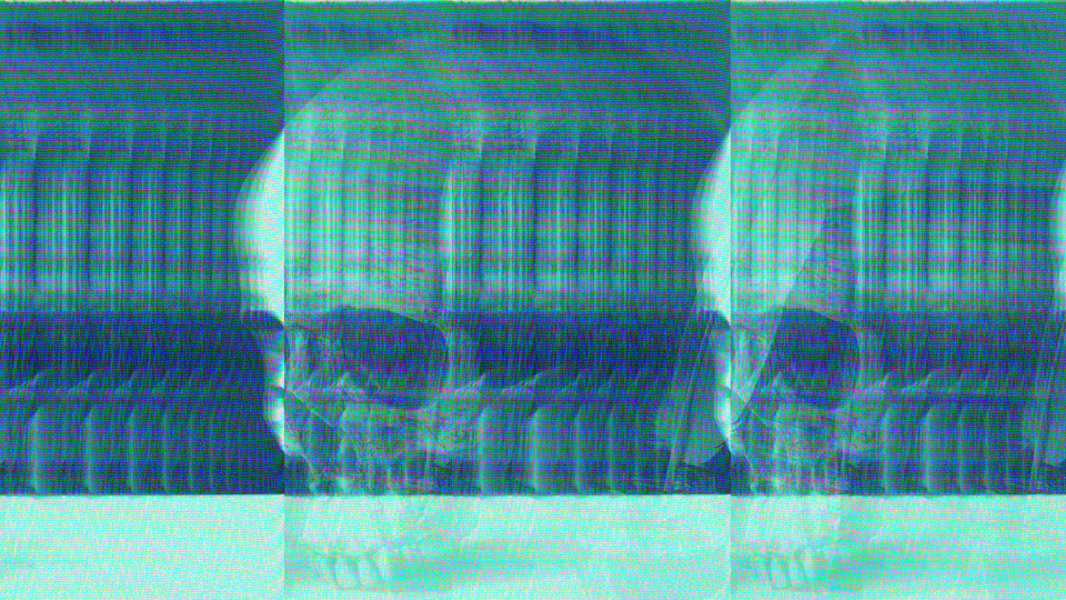
 Howler generating recursive tunnel patterns through scanline-level video feedback with zoom, decay, and hue rotation.
Overview
Howler is a video feedback loop simulator inspired by the BBC Radiophonic Workshop's howl-round technique: the method used to create the original Doctor Who title sequence in 1963. A camera was pointed at its own monitor, and the resulting feedback loop produced endlessly evolving, self-similar tunnel patterns. Howler recreates this process entirely in digital hardware using block RAM as a persistent canvas.
Each scanline is read back from a feedback buffer at a transformed address, blended with new incoming video, hue-rotated, and written back. Over successive frames, this IIR (Infinite Impulse Response) feedback loop builds recursive, blooming structures that tunnel inward or outward depending on the zoom setting. The result is organic, evolving imagery that responds to your input video like a living mirror.
Howler's six knobs control the spatial and tonal character of the feedback loop. Zoom sets the spatial scale of recursion. Decay controls how quickly old frames fade. Inject determines how much new video enters the loop. Color Drift rotates the hue on each feedback pass. H Shift slides the feedback sideways each frame. Brightness sets the output gain. Five toggle switches add polarity control, self-excitation noise, channel separation, and a freeze function.
Howler is at its most dramatic when you find the sweet spot between Decay and Inject where the feedback loop is just barely self-sustaining. Small changes to either knob can push the image from gentle trails into full recursive bloom.
What's In a Name?
The name Howler refers to the howl-round, a technique where audio or video feedback creates a self-reinforcing loop. In audio, pointing a microphone at a speaker creates a piercing howl. In video, pointing a camera at its own monitor creates an infinite tunnel. BBC graphic designer Bernard Lodge famously exploited this visual howl-round to create the original Doctor Who title sequence in 1963. Howler channels that same spirit of controlled feedback: harnessing a process that wants to run wild and shaping it into something beautiful.
Quick Start
- Feed a live camera or any input signal. Set Zoom (Knob 1) to center and Decay (Knob 2) to about 75%. You should see a ghostly echo of the input trailing behind motion.
- Turn Inject (Knob 3) up to about 50%. The input image now blends visibly into the feedback buffer, and recursive copies begin to appear, stacking inward like a tunnel.
- Slowly increase Color Drift (Knob 4). Watch as each recursive layer shifts in hue, creating a rainbow spiral effect that evolves continuously.
- Toggle Zoom Polar (Switch 7) to Contract. The tunnel reverses direction: instead of blooming outward, the recursion collapses inward toward the center.
Parameters
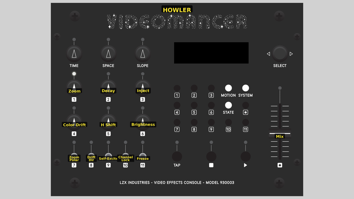 Videomancer's front panel with Howler active. Knobs 1–6 (top two rows of left cluster), Toggle switches 7–11 (bottom row of left cluster), Fader 12 (right side).
Knob 1 — Zoom
| Property | Value |
|---|---|
| Range | -100.0% – 100.0% |
| Default | 12.6% |
Zoom controls the spatial scale of the feedback read-back. The BRAM buffer is read at a transformed address that maps each pixel through a zoom factor centered on the middle of the screen. At 0%, the zoom factor is at its minimum, producing extreme spatial compression where the entire buffer is squeezed into a narrow band. At 50%, the zoom factor is 1.0: a one-to-one mapping that produces a simple echo with no spatial transformation. At 100%, the maximum zoom stretches the buffer contents outward. The direction of stretching depends on Zoom Polar (Switch 7).
The zoom factor operates as a read stride. Expansion means each feedback pass samples a wider region of the buffer, magnifying the center. Contraction means each pass samples a narrower region, creating the classic inward-tunneling effect.
Knob 2 — Decay
| Property | Value |
|---|---|
| Range | 0.0% – 100.0% |
| Default | 75.1% |
Decay controls the persistence of the feedback loop. Each pixel read from the buffer is multiplied by this value before being combined with the new input. At 0%, the buffer contents are multiplied by zero: no feedback survives, and the output is purely the injected input. At 100%, the full buffer value persists, and the feedback loop becomes maximally self-sustaining. High decay values produce long, luminous trails. Low values produce short, fading echoes.
Knob 3 — Inject
| Property | Value |
|---|---|
| Range | 0.0% – 100.0% |
| Default | 50.0% |
Inject controls how much of the input video is added into the feedback buffer on each pass. At 0%, no new video enters the loop, and the buffer contents evolve purely through feedback. At 100%, the full input signal is added. The balance between Inject and Decay determines whether the feedback loop grows, sustains, or fades. When both are high, the buffer saturates quickly into bright white. When both are moderate, the loop finds a dynamic equilibrium.
With Inject at zero and Self-Excite (Switch 9) off, the feedback loop receives no new energy. The image will fade to black over several frames as Decay attenuates the buffer contents.
Knob 4 — Color Drift
| Property | Value |
|---|---|
| Range | 0.0% – 100.0% |
| Default | 12.5% |
Color Drift applies a hue rotation to the U and V chrominance channels on each feedback pass. At 0%, no rotation occurs and colors are preserved through the feedback loop. As the value increases, each recursive layer shifts further in hue, producing rainbow spirals and continuously evolving color patterns. The rotation uses a Givens approximation: a small-angle rotation where U and V are cross-multiplied by a drift coefficient. The direction of rotation is set by Drift Dir (Switch 8).
Knob 5 — H Shift
| Property | Value |
|---|---|
| Range | 0.0% – 100.0% |
| Default | 0.0% |
H Shift applies a horizontal spatial drift to the feedback read address. An accumulator advances by this amount each frame, so the feedback content slides sideways over time. At 0%, the feedback buffer is read at its original horizontal position. As the value increases, the sideways drift accelerates. In SD video modes, the horizontal shift wraps seamlessly around the active picture width, so content that slides off one edge reappears on the other.
Knob 6 — Brightness
| Property | Value |
|---|---|
| Range | 0.0% – 100.0% |
| Default | 50.0% |
Brightness applies an output gain to the luminance channel after all feedback processing. At 0%, the output is black. At 50% (center), the luminance passes at unity gain. At 100%, the luminance is amplified to double brightness, with saturating clamp at maximum white. Brightness affects only the final output: the feedback buffer stores the pre-brightness signal, so gain changes don't compound through the loop.
Because brightness is applied after the feedback write-back, you can dim the output for a subtle effect while the internal feedback loop continues at full strength. This is useful for blending Howler's output with other programs in a signal chain.
Switch 7 — Zoom Polar
| Property | Value |
|---|---|
| Off | Expand |
| On | Contract |
| Default | Expand |
Zoom Polar selects whether the zoom factor expands or contracts the feedback read address. Set to Expand, the read stride magnifies the buffer outward from center: the tunnel blooms. Set to Contract, the stride compresses inward: the tunnel collapses toward the center. This is the difference between the camera zooming in on its monitor versus zooming out.
Switch 8 — Drift Dir
| Property | Value |
|---|---|
| Off | CW |
| On | CCW |
| Default | CW |
Drift Dir selects the direction of the Color Drift hue rotation. Set to CW, the hue rotates clockwise through the color wheel on each feedback pass. Set to CCW, it rotates counterclockwise. The visual difference is whether the rainbow spiral cycles through red-yellow-green-blue or blue-green-yellow-red.
Switch 9 — Self-Excite
| Property | Value |
|---|---|
| Off | Off |
| On | On |
| Default | Off |
Self-Excite replaces the video input with pseudorandom noise from two LFSR (Linear Feedback Shift Register) generators. When enabled, no external video enters the feedback loop. Instead, the LFSRs seed the buffer with noise, and the feedback process: zoom, decay, color drift: sculpts that noise into evolving abstract patterns. This transforms Howler from a processing effect into a self-contained synthesis engine.
With Self-Excite enabled, the output is entirely generated by the feedback loop. The Inject knob still controls how much noise energy enters the loop on each pass, so it remains an important control even without an external video source.
Switch 10 — Channel Lock
| Property | Value |
|---|---|
| Off | Indep |
| On | Locked |
| Default | Locked |
Channel Lock determines whether the U and V chrominance channels rotate together or independently during color drift. Set to Locked, both channels undergo the same Givens rotation, preserving the hue relationship. Set to Indep, the V channel rotation is inverted relative to U, causing the two color axes to diverge. Independent mode produces more chaotic, saturated color evolution and can create complementary color splits.
Switch 11 — Freeze
| Property | Value |
|---|---|
| Off | Off |
| On | On |
| Default | Off |
Freeze halts all writes to the feedback buffer. The current buffer contents are preserved indefinitely, and the output continues to display the frozen frame. New input video is still processed through the pipeline but is not written back. Disabling Freeze resumes normal feedback operation. Use Freeze to capture a moment of the evolving feedback pattern.
Freeze is different from bypass: the feedback buffer holds its state, but you still see the processed output. Toggle Freeze on and off rapidly to create stuttering, frame-hold effects.
Fader 12 — Mix
| Property | Value |
|---|---|
| Range | 0.0% – 100.0% |
| Default | 100.0% |
Mix crossfades between the dry (unprocessed) input signal and the wet (feedback-processed) output. At 0%, the output is entirely the original input with no feedback visible. At 100%, the output is entirely the feedback engine result. Intermediate values blend the two, which is useful for layering the feedback pattern over the original video with partial transparency.
Background
The howl-round
The howl-round is one of the oldest electronic imaging techniques. In 1963, BBC graphic designer Bernard Lodge created the first Doctor Who title sequence by pointing a television camera at a monitor displaying its own output. The resulting feedback loop produced swirling, tunneling patterns that seemed impossibly complex for the technology of the era. The technique requires no computer, no software: just a camera, a monitor, and the emergent mathematics of recursive self-reference.
Howler implements this concept as a scanline-level IIR (Infinite Impulse Response) digital filter. Where the original BBC setup used optical feedback through physical space, Howler uses block RAM to store the previous frame and reads it back through a spatial transformation. The zoom, decay, and color drift controls correspond to the physical adjustments an engineer would make: moving the camera closer or further from the monitor (zoom), adjusting the monitor brightness (decay), and introducing color filters (drift).
Feedback dynamics
The core equation of Howler's feedback loop is deceptively simple: on each pixel, the output equals the decayed feedback plus the injected input, run through hue rotation. This is a first-order IIR filter: the output depends on its own past values. The zoom transformation makes it spatially recursive: each pixel reads from a different location in the buffer, creating the magnification or compression that produces tunnel effects.
The interplay of Decay and Inject governs the energy balance of the system. When the combined gain exceeds unity, the loop is supercritical: energy accumulates and the image saturates toward white. Below unity, the loop is subcritical and the image fades. At exactly unity, the system finds equilibrium, sustaining patterns indefinitely. The art of Howler is finding and riding that boundary.
Givens rotation
Howler's color drift uses a Givens rotation: a standard technique for rotating a two-dimensional vector by a small angle. The U and V chrominance channels form a 2D color vector, and the rotation matrix is approximated as:
U' = U - V × k / 512
V' = V + U × k / 512
where k is the drift coefficient derived from the Color Drift knob. This small-angle approximation avoids the need for sine and cosine lookup tables, making it efficient in FPGA logic. Over many feedback iterations, the cumulative rotation sweeps through the full color wheel, producing the characteristic rainbow spiral.
Signal Flow
Signal Flow Notes
The feedback loop is the core interaction: the BRAM buffer holds the previous frame's processed output, and the address pipeline determines where in that buffer each pixel reads from. The zoom factor transforms the read address relative to the horizontal center, so pixels near the center read from nearby addresses (low distortion) while pixels near the edges read from distant addresses (high distortion). This center-outward magnification is what produces the tunnel geometry.
The write-back in stage P6 stores the pre-brightness accumulated signal, not the brightness-adjusted output. This means the brightness control affects only the display output, not the feedback loop itself. The loop's energy balance is governed entirely by Decay and Inject, making Brightness a safe output-stage adjustment.
H Shift accumulates per frame, not per pixel. The entire feedback buffer slides sideways by the same amount on each frame, creating a smooth scrolling effect. In SD modes, the wrap is seamless because the address is computed modulo the active picture width.
Exercises
These exercises progress from simple feedback trails to full self-exciting synthesis. Each builds on the previous, gradually engaging more of Howler's feedback controls.
Exercise 1: Basic Feedback Tunnel
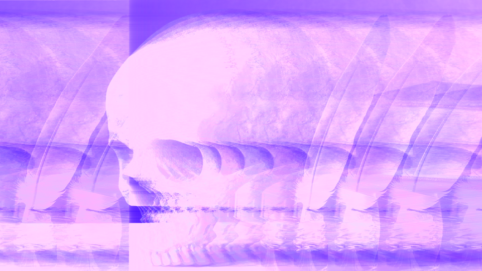
 Basic Feedback Tunnel — simulated result across source images.
Exercise Illustration
A description of the exercise illustration.
Learning Outcomes
Discover how zoom and decay interact to create the classic recursive tunnel effect.
Key Concepts
- Feedback is a recursive read-modify-write loop through BRAM
- Zoom sets the spatial scale of each recursive step
- Decay controls how quickly previous iterations fade
Video Source
A live camera feed or footage with recognizable shapes and strong contrast.
Steps
- Echo trail: Set Decay (Knob 2) to about 75% and Inject (Knob 3) to about 50%. Move your hand or an object in front of the camera. You should see ghostly echoes trailing behind the motion.
- Tunnel in: Set Zoom (Knob 1) slightly below center, around 40%. The echoes shrink inward on each pass, creating a tunnel that recedes into the center of the screen.
- Tunnel out: Toggle Zoom Polar (Switch 7) to Contract. The tunnel reverses (echoes now bloom outward from the center.)
- Balance the loop: Slowly increase Decay until the tunnel pattern sustains itself without fading. You're looking for the threshold where the loop is just barely self-sustaining.
- Mix blend: Pull the Mix fader (Fader 12) to about 70% to see the original input layered beneath the tunnel pattern.
Settings
| Control | Value |
|---|---|
| Zoom | ~40% |
| Decay | ~75% |
| Inject | ~50% |
| Color Drift | 0% |
| H Shift | 0% |
| Brightness | 50% |
| Zoom Polar | Expand |
| Drift Dir | CW |
| Self-Excite | Off |
| Channel Lock | Locked |
| Freeze | Off |
| Mix | ~70% |
Exercise 2: Rainbow Spiral
 Rainbow Spiral — simulated result across source images.
Exercise Illustration
A description of the exercise illustration.
Learning Outcomes
Add color drift and horizontal shift to create evolving, colorful feedback patterns.
Key Concepts
- Givens rotation shifts hue on each feedback pass
- H Shift adds horizontal motion to the feedback loop
- Channel Lock changes the character of color evolution
Video Source
High-contrast footage with distinct shapes (geometric patterns or silhouettes work well.)
Steps
- Start from Exercise 1: Keep your tunnel running at moderate decay.
- Add color: Slowly increase Color Drift (Knob 4) from zero. Each recursive layer acquires a different hue, and the tunnel becomes a rainbow spiral.
- Reverse direction: Toggle Drift Dir (Switch 8) to CCW. The color cycle reverses.
- Horizontal motion: Increase H Shift (Knob 5) slightly. The feedback pattern slides sideways, frame by frame, creating a scrolling spiral.
- Unlock channels: Toggle Channel Lock (Switch 10) to Indep. The U and V chrominance channels now rotate in opposite directions, producing more saturated, split-complementary color patterns.
- Freeze a moment: When you see a pattern you like, toggle Freeze (Switch 11) to On. The buffer holds its state. Toggle it off to resume.
Settings
| Control | Value |
|---|---|
| Zoom | ~40% |
| Decay | ~75% |
| Inject | ~40% |
| Color Drift | ~30% |
| H Shift | ~15% |
| Brightness | 50% |
| Zoom Polar | Contract |
| Drift Dir | CW |
| Self-Excite | Off |
| Channel Lock | Indep |
| Freeze | Off |
| Mix | 100% |
Exercise 3: Self-Exciting Synthesis
 Self-Exciting Synthesis — simulated result across source images.
Exercise Illustration
A description of the exercise illustration.
Learning Outcomes
Use Howler as a standalone video synthesizer with no external input.
Key Concepts
- Self-Excite seeds the feedback loop with LFSR noise
- The feedback loop sculpts noise into structured patterns
- Inject controls the energy entering the system
Video Source
No source video needed (disconnect or ignore the input signal.)
Steps
- Enable noise: Toggle Self-Excite (Switch 9) to On. The input is replaced with pseudorandom noise from two LFSR generators.
- Build the loop: Set Decay to ~70%, Inject to ~50%, and Zoom to ~40%. The noise begins to organize into recursive structures as the feedback loop magnifies and reinforces certain patterns.
- Add drift: Increase Color Drift to ~40%. The evolving noise patterns gain color, cycling through the spectrum as the loop iterates.
- Brightness bloom: Increase Brightness (Knob 6) above 50% to amplify the luminance. The patterns brighten and bloom, creating vivid self-generated imagery.
- Explore: Slowly sweep Zoom and Decay to find different self-sustaining regimes. Some settings produce stable geometric patterns; others produce chaotic, constantly evolving textures.
Settings
| Control | Value |
|---|---|
| Zoom | ~40% |
| Decay | ~70% |
| Inject | ~50% |
| Color Drift | ~40% |
| H Shift | ~20% |
| Brightness | ~70% |
| Zoom Polar | Expand |
| Drift Dir | CW |
| Self-Excite | On |
| Channel Lock | Locked |
| Freeze | Off |
| Mix | 100% |
Glossary
-
BRAM: Block RAM; dedicated memory blocks within the FPGA used as the persistent feedback buffer.
-
Decay: The attenuation factor applied to the feedback buffer on each pass, controlling how quickly previous frames fade.
-
Givens Rotation: A 2D rotation technique applied to U and V chrominance channels to shift hue without requiring trigonometric lookup tables.
-
Howl-Round: A feedback loop created by pointing a camera at its own monitor, producing self-similar recursive imagery.
-
IIR Filter: Infinite Impulse Response filter; a system where the output depends on its own past values, creating persistent memory.
-
Inject: The amount of new input signal added into the feedback loop on each pass.
-
LFSR: Linear Feedback Shift Register; a simple pseudorandom number generator used for self-excitation noise.
-
Subcritical: A feedback loop state where energy dissipates faster than it accumulates, causing the image to fade.
-
Supercritical: A feedback loop state where energy accumulates faster than it dissipates, causing the image to saturate.