Bitcullis
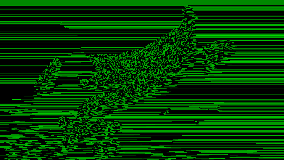
 Bitcullis applying luminance-modulated decimation and ordered dithering to create adaptive mosaic textures.
Overview
Bitcullis is a video bitcrusher with optional posterization, dithering, and bitswapping features. Its core function is to dynamically discard picture information, producing a mosaic grid of flat, rectangular shapes. Enabling other features results in a wider palette of visual effects ranging from aggressive colorization to patterns reminiscent of video snow. The unique feature of Bitcullis is its ability to map luminance to horizontal displacement, warping the shape of the mosaic tiles in a novel, unexpected way.
At low settings, Bitcullis can create subtle mosaic textures or gentle posterization. At extreme settings, it reduces video to hard-edged block graphics, glitch patterns, and abstract digital structures that bear little resemblance to the source.
Luma modulation is the signature effect. The Luma to Hori parameter creates adaptive mosaics where the block pattern follows the image content. This is what makes Bitcullis unique.
What's In a Name?
The name Bitcullis has a dual-layered meaning. The first meaning is a portmanteau of bit, the fundamental digital unit, and portcullis, the iron gate of a castle. It's a gate that controls which bits pass through. The second meaning refers to the process of decimation: bits are culled from the stream.
Quick Start
- Set Hori Decimate (Knob 1) and Vert Decimate (Knob 2) to low values, creating a mosaic pattern. The culling of bits has begun!
- Set Luma to Hori to a high value. Notice how brighter areas retain more detail than darker areas in the horizontal axis: bright regions resist decimation. This is the "killer app" of Bitcullis.
- Adjust Vert Decimate. As you increase Knob 2 clockwise, less vertical information is removed. Because Luma to Hori is still active, the shape of the mosaic tiles becomes wavy from side to side.
Parameters
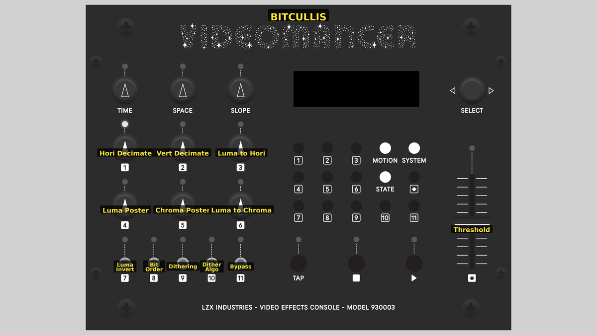 Videomancer's front panel with Bitcullis active. Knobs 1–6 (top two rows of left cluster), Toggle switches 7–11 (bottom row of left cluster), Fader 12 (right side).
Knob 1 — Hori Decimate
| Property | Value |
|---|---|
| Range | 0.0% – 200.0% |
| Default | 200.0% |
Hori Decimate, the horizontal decimation frequency, controls how much spatial information is discarded within each row of pixels. At 0%, fully counterclockwise, the minimum amount of horizontal information is preserved: all pixels in a row are reduced to a single, uniform color. As the value increases, more detail is revealed, and vertical bands of color become smaller and more numerous. At 100%, fully clockwise, all horizontal information is preserved: the horizontal resolution is the same as the source image.
Knob 2 — Vert Decimate
| Property | Value |
|---|---|
| Range | 0.0% – 100.0% |
| Default | 100.0% |
Vert Decimate, the vertical decimation frequency, controls how much spatial information is discarded within each column of pixels. At 0%, the minimum amount of vertical information is preserved. All pixels in a column are reduced to a single, uniform color. As the value increases, more detail is revealed, and horizontal bands of color become smaller and more numerous. At 100%, all vertical information is preserved. The resulting vertical resolution is the same as the source image.
Vert Decimate combines with Hori Decimate (Parameter 1) to define the scale and proportions of mosaic tiles. Nearly equal values create roughly square blocks, unequal values create rectangles.
Knob 3 — Luma to Hori
| Property | Value |
|---|---|
| Range | 0.0% – 100.0% |
| Default | 0.0% |
Luma to Hori modulates the horizontal decimation with luminance, making the size and shape of mosaic tiles dependent on the image brightness. At 0%, fully counterclockwise, decimation is uniform across the image. Increasing this control causes bright areas to retain more horizontal detail while dark areas become more heavily decimated. This is Bitcullis's key control. The size and shape of mosaic tiles follows the brightness tones of the source image, rendering adaptive pixelation that reveals the underlying content.
Luma to Hori is processed before Vert Decimate, on a per-scanline basis. This results in the characteristic effect of the left and right sides of mosaic tiles appearing wiggly and wavy.
Knob 4 — Luma Poster
| Property | Value |
|---|---|
| Range | 0.0% – 100.0% |
| Default | 100.0% |
Luma Poster controls the quantization of luminance values. At 0%, the luminance is reduced to only two levels, resulting in extreme banding. As Luma Poster is increased, more brightness levels are preserved, and more bands appear. At 100%, the full 10 bits of luminance pass through unchanged, disabling luminance posterization.
Knob 5 — Chroma Poster
| Property | Value |
|---|---|
| Range | 0.0% – 100.0% |
| Default | 100.0% |
Chroma Poster controls the quantization of chrominance values, independently of Luma Poster. At 0%, chroma is reduced to only two colors. As Chroma Poster is increased, more levels of hue and saturation are preserved, and more bands appear. At 100%, chroma passes through unchanged, disabling chroma posterization.
Setting Chroma Poster high while keeping Luma Poster low creates a silkscreen-like effect where brightness remains smooth, but colors snap to a reduced palette. The reverse combination (high Luma Poster, low Chroma Poster) produces banded tonal steps with smooth color transitions.
Knob 6 — Luma to Chroma
| Property | Value |
|---|---|
| Range | 0.0% – 100.0% |
| Default | 0.0% |
Luma to Chroma modulates saturation with luminance. At 0%, fully counterclockwise, saturation passes through unchanged: no modulation takes place. As the value increases, luminance exerts greater control over saturation: bright areas become more saturated, and dark areas become less saturated. At 100%, the modulation is at full strength.
Switch 7 — Luma Invert
| Property | Value |
|---|---|
| Off | Off |
| On | On |
| Default | Off |
Luma Invert reverses the tones of the luminance channel. This is the very first processing step, before decimation and all subsequent stages. This alters the outcome of all processing stages that depend on luminance, such as Luma to Hori (Parameter 3).
Switch 8 — Bit Order
| Property | Value |
|---|---|
| Off | Normal |
| On | Swapped |
| Default | Normal |
Bit Order reverses the place order of bits in each pixel channel. Bit-order reversal is a nonlinear permutation resulting in a chaotic, glitchy remapping of brightness and color values.
For the luminance channel, all 10 bits are reversed: the most significant bit on the far left is moved to the least significant place on the far right, and vice versa. For example, the binary value 1000000000 (decimal 512) becomes binary 0000000001 (decimal 1).
For the chroma channels (U and V), the highest bit is preserved, and only the lower nine bits are reversed. The highest bit is polarity, or the numerical sign of positive or negative. Preserving the polarity bit keeps colors in the same UV quadrant while still scrambling their values.
Switch 9 — Dithering
| Property | Value |
|---|---|
| Off | Disabled |
| On | Enabled |
| Default | Disabled |
Dithering injects noise before posterization, breaking up flat patterns and randomizing boundaries between bands. The noise pushes pixel values across quantization boundaries, creating a textured appearance. On each pixel, per each channel, Dithering adds or subtracts a decimal value ranging from zero to eight. Each channel has a dynamic range of 1024 possible values, so ±8 is less than one percent of deviation.
If posterization is disabled, the visual effect of Dithering is negligible.
Switch 10 — Dither Algo
| Property | Value |
|---|---|
| Off | Ordered |
| On | Random |
| Default | Ordered |
Dither Algo selects the algorithm for Dithering. Ordered dithering adds structure; Random dithering adds texture. With the switch set to Off, a fixed, Ordered pattern produces a regular stipple grid. The Ordered algorithm is based on a 4×4 Bayer matrix.
With the switch set to On, a Random noise source produces a texture reminiscent of film grain. The Random algorithm uses a pseudo-random linear feedback shift register (LFSR).
Switch 11 — Bypass
| Property | Value |
|---|---|
| Off | Off |
| On | On |
| Default | Off |
Bypass routes the unprocessed input signal directly to the output, circumventing all Bitcullis processing stages. The sync delay pipeline still aligns timing, so there is no glitch on transition. Use Bypass for instant A/B comparison between the raw input and the processed result.
Fader 12 — Threshold
| Property | Value |
|---|---|
| Range | 0.0% – 100.0% |
| Default | 0.0% |
Threshold applies a luminance key at the end of the processing chain. Any pixel with a luminance value lower than the threshold is “keyed out”, replaced with black. At 0%, everything passes through, disabling the key operation. As the Threshold value increases, more of the image is keyed out. At 100%, only the very brightest pixels survive.
Threshold interacts powerfully with Luma Poster and Chroma Poster. Because posterization creates hard boundaries between tonal bands, the key Threshold cuts cleanly between levels. With Bit Order set to Swapped, Threshold cuts through the chaotic value mapping in wondrous and unexpected ways.
Background
Spatial decimation
Digital video is made of discrete numbers: brightness and color values laid out on a grid of pixels. Most video processing tries to hide that fact, making the grid and the tone gradients as smooth and invisible as possible. Bitcullis does the opposite. It takes the digital structure of the signal and makes it the subject.
Bitcullis's horizontal and vertical decimation controls implement sample and hold downsampling. It's the same as reducing the resolution of an image and then increasing it without smooth interpolation, using the nearest neighbor method. Pixels are enlarged to be visible as uniform blocks. This is also known as decimation because it discards information.
Decimation frequencies are controlled by an accumulator, causing tile boundaries to shift and alias in interesting ways as the decimation values change.
Posterization
When the possible values of pixels are constrained, smooth gradients collapse into flat regions separated by hard edges. This effect is called posterization, named after the appearance of block-printed posters. That printing technique doesn't allow inks to mix, and can only define discrete areas with specific colors. Bitcullis applies posterization independently of the luminance and chrominance channels, so you can reduce the number of brightness values while leaving color gradients smooth, or vice versa.
Dithering
Dithering is a technique for improving the subjective dynamic range of media with low bit depth. For an image, that means the appearance of more tonal levels than are actually present. Dithering works by adding a small of noise to the signal before quantization. The noise pushes colors across quantization boundaries to break up the bands of color and produce the illusion of intermediate tones. It's a form of perceptual coding, exploiting the limitations in human vision to reduce the amount of information needed to achieve a subjective level of quality. Halftone printing uses a different technique to achieve similar results.
Signal Flow
Signal Flow Notes
Two key interactions:
-
Luminance-driven modulation: The luminance channel drives two modulation controls. Luma to Hori varies the horizontal decimation frequency pixel-by-pixel based on brightness. Luma to Chroma varies the chroma saturation based on brightness.
-
Processing order: Decimation happens before posterization, so the posterizer quantizes the color palette of the pixelated signal. Dithering sits between decimation and posterization, adding noise to the blocky signal before its colors get quantized.
Order matters. The signal chain is: Inversion → Modulation → Decimation → Dithering → Posterization → Bit Reversal → Threshold. Each stage transforms the signal before the next one sees it.
Exercises
These exercises progress from simple decimation to full signal deconstruction. Each exercise builds on the previous one, gradually engaging more of the processing chain.
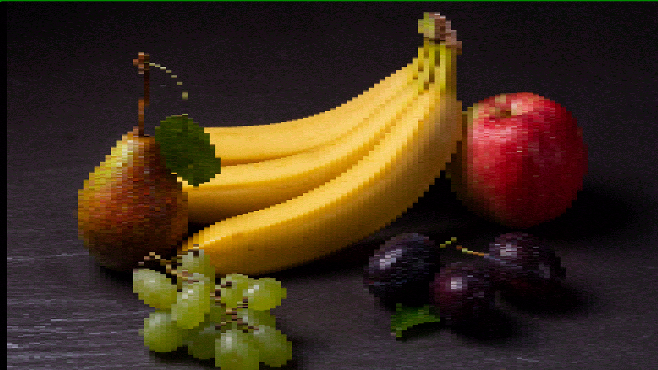
Exercise 1: Mosaic Pixelation
 Mosaic Pixelation — simulated result across source images.
Exercise Illustration
A description of the exercise illustration.
Learning Outcomes
Learn how decimation and luminance modulation interact to create adaptive mosaic textures.
Key Concepts
- Decimation is sample-and-hold downsampling
- Horizontal and vertical axes are independent
- Luminance modulation creates content-adaptive mosaics
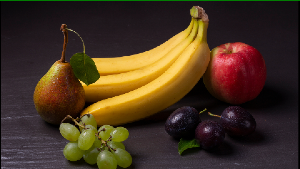
Video Source
A live camera feed or recorded footage with recognizable subjects.
Steps
- Horizontal bands: Turn Hori Decimate (Knob 1) slowly counter-clockwise. The image breaks into wide vertical bands of uniform color.
- Vertical bands: Now sweep Vert Decimate (Knob 2). The image breaks into horizontal bands.
- Square blocks: Set both Hori Decimate and Vert Decimate to about 30%. The image becomes a uniform mosaic of roughly square blocks.
- Adaptive mosaic: Slowly increase Luma to Hori (Knob 3) from 0 to 100%. The block grid responds to the image content: bright and dark regions render different block sizes. This is Bitcullis's signature effect.
- Inversion: Toggle Luma Invert (Switch 7). The modulation reverses. Block sizes swap between bright and dark regions.
Settings
| Control | Value |
|---|---|
| Hori Decimate | ~30% |
| Vert Decimate | 30% |
| Luma to Hori | 100% |
| Luma Poster | 0% |
| Chroma Poster | 50% |
| Luma to Chroma | 50% |
| Luma Invert | On |
| Bit Order | Normal |
| Dithering | Disabled |
| Dither Algo | Ordered |
| Bypass | Off |
| Threshold | 0% |
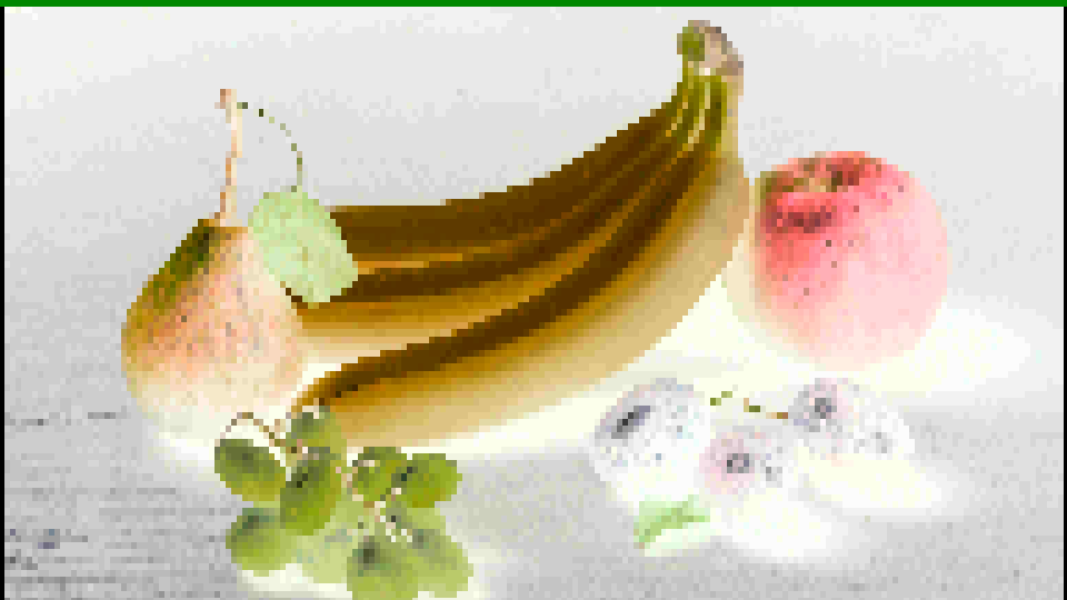
Exercise 2: Posterized Graphics
 Posterized Graphics — simulated result across source images.
Exercise Illustration
A description of the exercise illustration.
Learning Outcomes
Explore posterization and dithering interactions.
Key Concepts
- Posterization is quantization of pixel values
- Dithering masks quantization artifacts by adding structured noise
- Bit reversal is a nonlinear permutation
Video Source
Footage with gradual tonal transitions, such as skies, skin tones, or gradient test patterns.
Steps
- Prepare: Set moderate decimation (Hori Decimate and Vert Decimate ~50%) to create a visible mosaic.
- Luma posterization: Slowly increase Luma Poster (Knob 4). Smooth gradients collapse into staircase bands.
- Chroma posterization: Now increase Chroma Poster (Knob 5) while leaving Luma Poster at a moderate value. Colors snap to a reduced palette while brightness remains smooth.
- Dithering: Enable Dithering (Switch 9). The harsh posterization boundaries soften as noise pushes color values across quantization boundaries. Toggle Dither Algo (Switch 10) to compare Ordered vs. Random algorithms.
- Bit reversal: Enable Bit Order (Switch 8), setting it to Swapped. The orderly posterized levels explode into chaotic digital textures.
- Threshold: Adjust Threshold (Fader 12) to carve into the posterized result. Note how the threshold cuts cleanly along posterization boundaries.
Settings
| Control | Value |
|---|---|
| Hori Decimate | 50% |
| Vert Decimate | 50% |
| Luma to Hori | 50% |
| Luma Poster | 50% |
| Chroma Poster | 50% |
| Luma to Chroma | 50% |
| Luma Invert | Off |
| Bit Order | Normal |
| Dithering | Enabled |
| Dither Algo | Random |
| Bypass | Off |
| Threshold | 0% |
Exercise 3: Digital Texture Synthesis
 Digital Texture Synthesis — simulated result across source images.
Exercise Illustration
A description of the exercise illustration.
Learning Outcomes
Combine all stages for abstract digital textures.
Key Concepts
- Bitcullis is a layered signal deconstruction tool
- Each stage reduces or rearranges information
- Stages build on one another (decimation → dithering → posterization → bit-reversal → threshold)
Video Source
Any footage, especially high-contrast material.
Steps
- Strong modulation: Set Hori Decimate ~30%, Vert Decimate ~25%, Luma to Hori ~80%.
- Heavy processing: Increase both Luma Poster and Chroma Poster to high values.
- Random dithering: Enable Dithering using Random mode (Switch 10 On).
- Bit reversal: Enable Bit Order (Switch 8) for chaotic value remapping.
- Threshold sculpt: Lower the Threshold to ~40% to carve the texture.
- Inversion layers: Toggle Luma Invert to see how it reverses the entire modulation chain.
- Animate: Slowly sweep controls as the digital texture evolves in real time.
Settings
| Control | Value |
|---|---|
| Hori Decimate | ~89% |
| Vert Decimate | ~50% |
| Luma to Hori | 80% |
| Luma Poster | 80% |
| Chroma Poster | 80% |
| Luma to Chroma | 50% |
| Luma Invert | Off |
| Bit Order | Swapped |
| Dithering | Disabled |
| Dither Algo | Ordered |
| Bypass | Off |
| Threshold | 40% |
Glossary
-
Bit Depth: The number of discrete levels available to represent a signal; higher bit depth means finer gradations.
-
Chroma: The color information in a video signal, encoded as U and V components in YUV color space.
-
Decimation: Reducing spatial resolution by discarding samples at regular intervals, creating a blocky mosaic effect.
-
Dithering: Adding a small noise pattern before quantization to break up banding artifacts and simulate additional tonal levels.
-
Luma: The brightness component (Y) of a YUV video signal, representing perceived lightness.
-
Posterization: Reducing the number of distinct tonal levels in an image, creating flat areas of uniform color or brightness.
-
Proc Amp: Processing Amplifier; a gain-and-offset stage that applies brightness and contrast adjustment to a signal.
-
Quantization: Mapping a continuous range of values to a smaller set of discrete levels, producing visible steps in gradients.