Isotherm
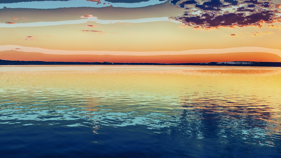 Isotherm rendering a live camera feed through the Ironbow false-color palette with isotherm contour lines tracing luminance boundaries.
Overview
Isotherm is a false-color thermal camera simulator. It treats the luminance of your input video as a temperature proxy and maps it through one of four color palettes: Ironbow, Rainbow, White-Hot, or Black-Hot: to produce imagery that looks like it came from a thermal imaging camera. Bright areas glow hot; dark areas read cold. The illusion is surprisingly convincing.
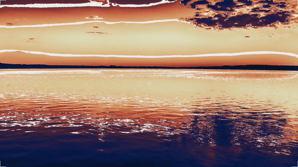
Beyond simple palette mapping, Isotherm draws isotherm contour lines at configurable intervals, marking the boundaries between luminance zones the way a weather map traces temperature gradients. A military-style HUD overlay adds a center crosshair and corner bracket reticles for a surveillance-camera aesthetic. An auto-range system continuously tracks the brightest and darkest pixels in the frame and stretches the palette to fill the available range, maximizing contrast automatically.
Isotherm is in the Analysis category because it reveals hidden structure in your video. Luminance gradients that are invisible in a normal image become vivid, color-coded boundaries.
What's In a Name?
An isotherm is a line on a map connecting points of equal temperature. Meteorologists use isotherms on weather charts to visualize temperature distribution across a region. In this program, the "temperature" is luminance, and the isotherm contour lines trace boundaries between brightness zones (topographic lines for a landscape of light.)
Quick Start
- Feed any video source into Videomancer and select Isotherm. The image immediately transforms into a false-color thermal view using the default Ironbow palette: dark blues for shadows, reds and oranges for midtones, and white-hot highlights.
- Turn Contour Wid (Knob 6) clockwise to about 50%. White contour lines appear, tracing boundaries between luminance zones like elevation lines on a topographic map.
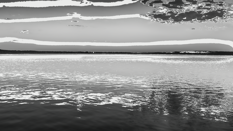
- Flip Palette A (Switch 7) to Hi to switch from Ironbow to the White-Hot palette. The image becomes a monochrome thermal view where brightness maps directly to "temperature."
- Turn Posterize (Knob 1) clockwise to increase the quantization level. The smooth gradient collapses into flat thermal bands, each a distinct color step (a heat map with visible zone boundaries.)
Parameters
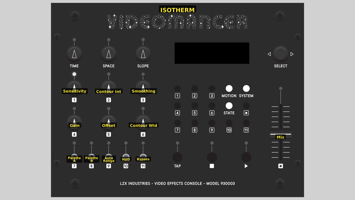 Videomancer's front panel with Isotherm active. Knobs 1–6 (top two rows of left cluster), Toggle switches 7–11 (bottom row of left cluster), Fader 12 (right side).
Knob 1 — Posterize
| Property | Value |
|---|---|
| Range | 0 – 7 |
| Default | 0 |
Posterize controls the number of quantization bands applied to the luminance signal before palette mapping. At the minimum setting, posterization is disabled and the full 10-bit luminance range maps smoothly through the palette. As you increase the value, luminance is progressively truncated to fewer bits, producing flat thermal zones separated by hard color boundaries. At the maximum setting, only eight distinct luminance levels survive (eight bold color bands like a simplified weather map.)
Posterization happens before palette lookup. The banded luminance feeds into the palette interpolator, so each band maps to a single palette color rather than a gradient.
Knob 2 — Contour Int
| Property | Value |
|---|---|
| Range | 1 – 8 |
| Default | 4 |
Contour Int sets the spacing between isotherm contour lines. This is a stepped control with eight intervals, from very dense (interval of 4 luminance steps) to very sparse (interval of 256 luminance steps). At the maximum setting, contour lines are disabled entirely. Denser intervals produce a web of fine contour lines revealing subtle luminance gradients. Wider intervals draw only the major boundaries.
Knob 3 — Smoothing
| Property | Value |
|---|---|
| Range | 0.0% – 100.0% |
| Default | 0.0% |
Smoothing applies horizontal IIR low-pass filtering to the input luminance before any palette processing. At the minimum setting, no smoothing is applied and pixel-level detail is preserved. Increasing the value progressively blurs the luminance channel horizontally, softening noise and high-frequency detail. At maximum smoothing, the IIR filter has a very long time constant, producing broad horizontal smears that emphasize slow luminance gradients.
Smoothing is especially useful with noisy or low-quality video sources. A small amount removes pixel noise that would otherwise produce jittery contour lines and palette flicker.
Knob 4 — Contrast
| Property | Value |
|---|---|
| Range | 0.0% – 100.0% |
| Default | 50.0% |
Contrast adjusts the gain applied to the luminance signal. In auto-range mode, this is a post-normalization contrast control centered at 50%: values below reduce contrast toward flat gray, values above increase contrast toward hard clipping. In manual mode (Auto Range off), Contrast acts as a raw gain multiplier on the input luminance. Either way, the center position (50%) passes the signal at unity gain.
Knob 5 — Brightness
| Property | Value |
|---|---|
| Range | 0.0% – 100.0% |
| Default | 50.0% |
Brightness offsets the luminance signal up or down. In auto-range mode, it shifts the normalized result. In manual mode, it adds a DC offset to the gained signal. The center position (50%) adds no offset. Turning counterclockwise darkens the image; turning clockwise brightens it. Combined with Contrast, this gives full manual control over how the input luminance maps to palette colors.
Knob 6 — Contour Wid
| Property | Value |
|---|---|
| Range | 0.0% – 100.0% |
| Default | 25.0% |
Contour Wid controls the thickness of isotherm contour lines. At the minimum value, contour lines are drawn as hairlines: one or two pixels wide. As the value increases, the lines thicken, eventually becoming wide bands that visually merge with the palette colors at very high settings. The contour width interacts with Contour Int: wide contour lines at narrow intervals can fill most of the image with white.
Setting both Contour Wid high and Contour Int to a dense interval may produce a mostly-white image. Reduce one or both to restore visible palette color beneath the contour overlay.
Switch 7 — Palette A
| Property | Value |
|---|---|
| Off | Lo |
| On | Hi |
| Default | Lo |
Palette A is the high bit of the two-bit palette selector. Combined with Palette B (Switch 8), it selects one of four color palettes. Flipping this switch changes the upper bit of the palette index, jumping between palette pairs.
Switch 8 — Palette B
| Property | Value |
|---|---|
| Off | Lo |
| On | Hi |
| Default | Lo |
Palette B is the low bit of the two-bit palette selector. Combined with Palette A (Switch 7), it selects one of four color palettes. Flipping this switch changes the lower bit of the palette index, stepping between adjacent palettes.
Switch 9 — Auto Range
| Property | Value |
|---|---|
| Off | On |
| On | Off |
| Default | On |
Auto Range enables or disables automatic luminance normalization. With auto-range On (the default), Isotherm continuously tracks the minimum and maximum luminance in the frame and stretches the palette to span that range. This maximizes contrast regardless of the input signal level. With auto-range Off, the palette maps the raw input luminance directly, and Contrast and Brightness serve as manual gain and offset controls.
Auto-range is ideal for live camera feeds where lighting conditions change. For pre-processed or synthetic video with a known luminance range, disable auto-range and dial in contrast and brightness manually for precise palette mapping.
Switch 10 — HUD
| Property | Value |
|---|---|
| Off | Off |
| On | On |
| Default | Off |
HUD enables a heads-up display overlay. When set to On, a white center crosshair and four corner bracket reticles are drawn on top of the thermal image. The HUD elements are resolution-adaptive and remain centered regardless of video format. The crosshair is 40 pixels across; corner brackets extend 40 pixels along each edge.
Switch 11 — Invert Map
| Property | Value |
|---|---|
| Off | Off |
| On | On |
| Default | Off |
Invert Map reverses the direction of the palette mapping. When Off, low luminance maps to the cold end of the palette and high luminance maps to the hot end. When On, the mapping is inverted: bright areas read cold and dark areas read hot. This is equivalent to flipping the thermal polarity on a real thermal camera.
Palette A (Switch 7) and Palette B (Switch 8) form a two-bit binary palette selector:
| Palette A | Palette B | Palette |
|---|---|---|
| Lo | Lo | Ironbow — black to deep blue to red to orange to yellow to white |
| Hi | Lo | White-Hot — monochrome black-to-white ramp |
| Lo | Hi | Rainbow — full spectral sweep: violet to blue to cyan to green to yellow to red to white |
| Hi | Hi | Black-Hot — inverted monochrome: white-to-black ramp |
The Ironbow palette mimics the classic look of uncooled thermal cameras. Rainbow is the most colorful, revealing fine luminance gradients as distinct hues. White-Hot and Black-Hot are monochrome variants useful for high-contrast analysis.
:::
Fader 12 — Mix
| Property | Value |
|---|---|
| Range | 0.0% – 100.0% |
| Default | 100.0% |
Mix crossfades between the dry (unprocessed) input signal and the wet (false-color) output. At 0%, the output is the original input video with no thermal processing visible. At 100% (the default), the output is fully false-colored. Intermediate values blend the two, creating a translucent thermal overlay on top of the source image. This is useful for orientation: you can see the original scene underneath the thermal coloring.
Background
False-Color Imaging
False-color imaging assigns arbitrary colors to measurable quantities. In scientific imaging, false color reveals information invisible to the naked eye: infrared cameras render heat as color, satellite imagery maps vegetation health, and medical scans highlight tissue density. The technique works because the human visual system is far more sensitive to color differences than to luminance differences. A smooth gray gradient might look uniform, but map it through a rainbow palette and subtle variations leap out in vivid hues.
Isotherm applies this principle to video luminance. The input luma is treated as a scalar field: a "temperature" that varies across the frame: and the palette maps that scalar to a color. This transforms any video source into a thermal-style visualization.
Piecewise-Linear Palettes
Rather than storing a full 1024-entry lookup table for each palette, Isotherm defines 16 key-point colors per palette and interpolates linearly between them. The input luminance selects a segment between two adjacent key-points, and a fractional index drives piecewise-linear blending across all three color channels (Y, Cb, Cr) simultaneously. This approach requires only registers: no block RAM: while producing smooth color gradients.
Auto-Ranging
Real thermal cameras use automatic gain control to stretch the sensor's output to fill the display range, ensuring maximum contrast regardless of the scene's absolute temperature. Isotherm implements a digital equivalent: an IIR envelope tracker follows the minimum and maximum luminance values across each frame, gradually decaying toward the extremes. The tracked range normalizes the input before palette mapping, so even low-contrast scenes produce vivid, full-range thermal imagery.
Signal Flow
Signal Flow Notes
The key architectural decision is that the entire palette mapping operates on the Y (luminance) channel only. The input Cb and Cr channels are not processed at all: they are delayed and available only for the dry side of the wet/dry mix. The "color" in the false-color output comes entirely from the palette lookup, which outputs all three channels (Y, Cb, Cr) as a function of the single luminance input.
Auto-range and manual mode share the same pipeline stages but take different paths through them. In auto mode, stages 2 and 3 normalize the input to the tracked min/max envelope, then stage 3b applies contrast and brightness as post-normalization adjustments. In manual mode, stage 3 applies contrast as raw gain and brightness as a DC offset directly, bypassing the auto-range normalization.
Contour lines are generated from the post-posterize luminance. This means posterization creates discrete zones, and contour lines appear at the boundaries between those zones. More posterization bands mean more contour lines at a given interval (and fewer bands mean fewer, bolder contours.)
Exercises
These exercises progress from basic palette exploration to precision thermal analysis techniques. Each builds familiarity with a different subsystem of Isotherm's processing chain.
Exercise 1: Thermal Palette Survey
 Thermal Palette Survey — simulated result across source images.
Exercise Illustration
A description of the exercise illustration.
Learning Outcomes
Explore all four palettes and understand how each renders the same scene differently.
Key Concepts
- Palette selection via two-bit toggle combination
- Ironbow mimics thermal camera aesthetics
- Monochrome palettes (White-Hot, Black-Hot) emphasize pure luminance structure
Video Source
A live camera feed with a mix of bright and dark areas: a face lit from one side, a lamp beside a shadow, or any scene with a wide tonal range.
Steps
- Ironbow baseline: Start with the default palette: both Palette A (Switch 7) and Palette B (Switch 8) set to Lo. This is Ironbow: the classic thermal camera look. Notice how shadows appear deep blue and bright areas glow orange to white.
- Rainbow spectrum: Flip Palette B to Hi (keeping Palette A on Lo). This selects Rainbow. The same scene now shows a full spectral sweep: violets in the darkest areas cycling through blue, cyan, green, yellow, and red to white.
- White-Hot clarity: Flip Palette A to Hi and Palette B back to Lo. This is White-Hot: a pure monochrome ramp. Compare how much luminance detail is visible versus the colored palettes.
- Inverted polarity: Set both switches to Hi for Black-Hot: the inverted monochrome ramp. Notice how your perception of "hot" and "cold" reverses.
- Compare inversions: Return to Ironbow and toggle Invert Map (Switch 11). Compare inverted Ironbow to the Black-Hot palette: they look similar but are not identical because Ironbow's color curve is asymmetric.
Settings
| Control | Value |
|---|---|
| Posterize | 0 |
| Contour Int | 8 (disabled) |
| Smoothing | 0% |
| Contrast | 50% |
| Brightness | 50% |
| Contour Wid | 0% |
| Palette A | Lo |
| Palette B | Lo |
| Auto Range | On |
| HUD | Off |
| Invert Map | Off |
| Mix | 100% |
Exercise 2: Contour Mapping
 Contour Mapping — simulated result across source images.
Exercise Illustration
A description of the exercise illustration.
Learning Outcomes
Learn to use isotherm contour lines and posterization to create topographic luminance maps.
Key Concepts
- Contour lines mark luminance zone boundaries
- Posterization creates discrete thermal bands
- Contour interval and width interact to control line density
Video Source
A slowly moving video source with smooth gradients (clouds, water, or gently lit surfaces work well.)
Steps
- Draw contour lines: Enable contour lines: set Contour Int (Knob 2) to interval 3 (about 40%) and Contour Wid (Knob 6) to about 25%. White lines appear tracing luminance boundaries.
- Sweep density: Slowly sweep Contour Int through all eight steps. At the densest setting, fine contour lines reveal every subtle gradient. At wider intervals, only major luminance boundaries are marked.
- Add thermal bands: Increase Posterize (Knob 1) to step 4 (about halfway). The smooth palette collapses into flat thermal bands with hard edges. Contour lines now trace the edges of these bands.
- Thicken the lines: Increase Contour Wid to about 75%. The contour lines thicken into wide white bands separating the thermal zones.
- Surveillance overlay: Enable HUD (Switch 10). The crosshair and corner brackets appear, completing the surveillance-camera aesthetic.
Settings
| Control | Value |
|---|---|
| Posterize | 4 |
| Contour Int | 3 |
| Smoothing | 0% |
| Contrast | 50% |
| Brightness | 50% |
| Contour Wid | 25% |
| Palette A | Lo |
| Palette B | Lo |
| Auto Range | On |
| HUD | On |
| Invert Map | Off |
| Mix | 100% |
Exercise 3: Abstract Heat Landscapes
 Abstract Heat Landscapes — simulated result across source images.
Exercise Illustration
A description of the exercise illustration.
Learning Outcomes
Combine smoothing, posterization, manual gain, and palette inversion to create abstract compositions that depart from the thermal camera simulation.
Key Concepts
- Smoothing before palette mapping creates soft, painterly heat gradients
- Manual contrast and brightness control precise palette window and level
- Mix blends the thermal overlay with the original source
Video Source
Any visually complex footage: architectural scenes, nature footage, or abstract video synthesis patterns.
Steps
- Manual exposure: Disable auto-range: flip Auto Range (Switch 9) to Off. The palette now maps the raw input luminance.
- Narrow the window: Set Contrast (Knob 4) to about 60% and Brightness (Knob 5) to about 40%. This narrows the palette window, concentrating color detail in the midtones.
- Soften the field: Increase Smoothing (Knob 3) to about 50%. The input luminance blurs horizontally, softening pixel detail into broad horizontal streaks of color.
- Quantize to bands: Set Posterize (Knob 1) to step 3. The smooth streaks quantize into bold, flat thermal bands.
- Spectral stripes: Switch to the Rainbow palette (Palette A: Lo, Palette B: Hi). The bands become vivid spectral stripes.
- Blend with source: Pull Mix (Fader 12) down to about 50%. The original source image bleeds through the thermal overlay, creating a translucent heat map effect.
- Flip hot and cold: Toggle Invert Map (Switch 11) to flip the palette direction. Observe how the composition changes as "hot" and "cold" swap roles.
Settings
| Control | Value |
|---|---|
| Posterize | 3 |
| Contour Int | 8 (disabled) |
| Smoothing | 50% |
| Contrast | 60% |
| Brightness | 40% |
| Contour Wid | 0% |
| Palette A | Lo |
| Palette B | Hi |
| Auto Range | Off |
| HUD | Off |
| Invert Map | On |
| Mix | 50% |
Glossary
-
Auto-Range: Automatic normalization of input luminance to fill the full palette range, implemented as an IIR envelope tracker following per-frame min/max values.
-
Contour Line: A line drawn at boundaries between luminance zones, analogous to isotherms on a weather map or elevation contours on a topographic map.
-
False Color: A visualization technique that maps a scalar quantity (here, luminance) to an arbitrary color palette, revealing structure invisible in the original grayscale signal.
-
HUD: Heads-Up Display; an overlay of geometric elements (crosshair, brackets) drawn on top of the processed image.
-
IIR Filter: Infinite Impulse Response filter; a recursive digital filter where each output depends on previous outputs, producing exponential smoothing.
-
Ironbow: A false-color palette inspired by blackbody radiation, progressing from black through deep blue, red, orange, and yellow to white.
-
Isotherm: A line of equal temperature; in this program, a contour marking a specific luminance level in the false-color rendering.
-
Key-Point: One of 16 anchor colors defining a palette; intermediate colors are linearly interpolated between adjacent key-points.
-
Normalize: Scaling a signal so its minimum maps to zero and its maximum maps to full scale, maximizing the use of the available dynamic range.
-
Piecewise-Linear: An interpolation method that connects discrete points with straight-line segments, approximating a smooth curve with minimal computation.
-
Posterize: Reducing the number of distinct luminance levels by truncating least-significant bits, creating flat bands of uniform value.
-
Proc Amp: Processing Amplifier; a gain-and-offset stage applying contrast (gain) and brightness (offset) adjustments to a signal.