Delirium
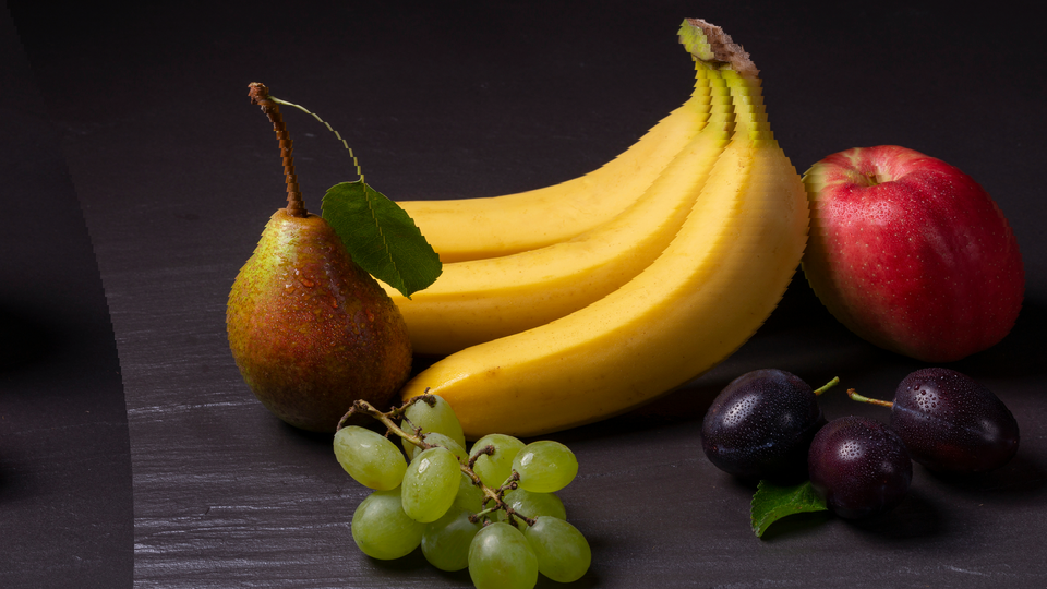
 Delirium applying cascaded sinusoidal distortion to warp a video signal into undulating, dreamlike waves.
Overview
Delirium is a two-layer sinusoidal distortion engine that bends and ripples video like a reflection on disturbed water. Each layer computes a sine wave that displaces pixels horizontally, stretching and compressing the image along a wave pattern. The two layers operate in cascade, meaning one layer distorts the already-distorted output of the other, producing compound wave interference patterns that can range from gentle undulation to full psychedelic delirium.
Each layer has independent controls for amplitude (wave depth), frequency (wave spacing), and speed (animation rate). The mode switch for each layer selects whether the sine wave varies by scanline (vertical striping) or by pixel position (horizontal ripple). When both layers are active with different modes and frequencies, they produce complex two-dimensional distortion fields that continuously evolve.
Start with one layer. Set Amplitude 2 (Knob 4) to zero and experiment with Layer 1 alone before engaging the second layer. This makes the distortion behavior much easier to understand.
What's In a Name?
The name Delirium captures the hallucinatory quality of its output: images that shimmer and warp as if seen through a fever dream. The effect is directly inspired by the battle background distortion system from the 1994 Super Nintendo game EarthBound (Mother 2), which used the same two-layer cascaded sinusoidal technique to create its iconic psychedelic combat scenes.
Quick Start
- Turn Amplitude 1 (Knob 1) to about 25%. The image begins to ripple with soft vertical waves (scanlines shift left and right following a sine curve.)
- Sweep Frequency 1 (Knob 2) slowly from low to high. At low values the wave is broad and gentle; at high values the image becomes tightly compressed and stretched in rapid succession.
- Increase Speed 1 (Knob 3) to animate the distortion. The wave pattern scrolls continuously, creating a liquid motion effect.
- Now bring Amplitude 2 (Knob 4) up to 25% and toggle Layer 2 Mode (Switch 8) to the opposite of Layer 1. Two perpendicular wave patterns interact, creating compound warping across both axes.
Parameters
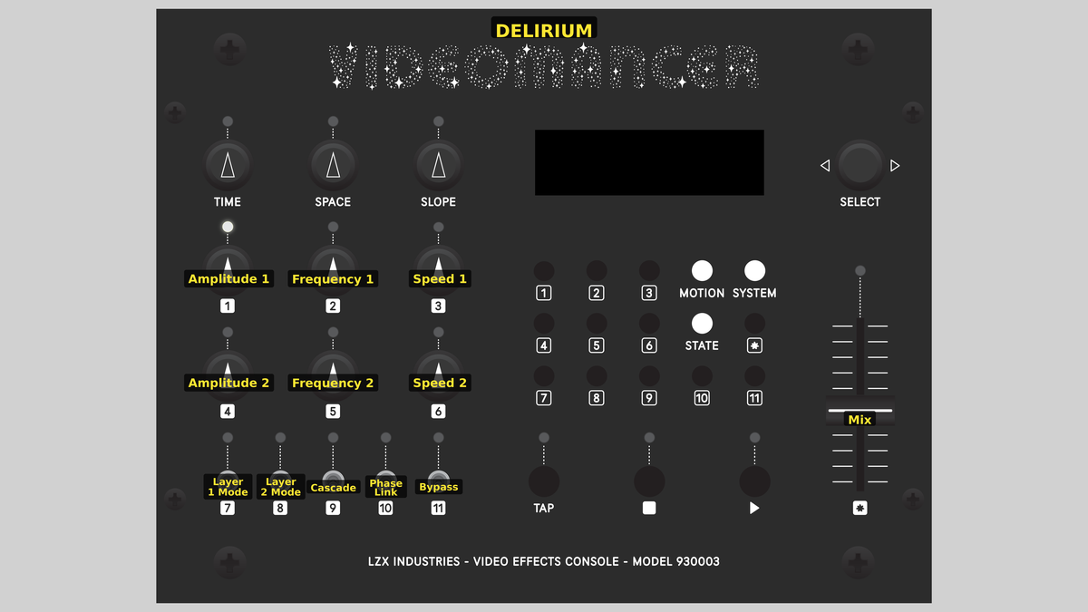 Videomancer's front panel with Delirium active. Knobs 1–6 (top two rows of left cluster), Toggle switches 7–11 (bottom row of left cluster), Fader 12 (right side).
Knob 1 — Amplitude 1
| Property | Value |
|---|---|
| Range | 0.0% – 100.0% |
| Default | 25.0% |
Amplitude 1 controls the distortion depth of Layer 1: how far pixels are displaced from their original position. At 0%, fully counterclockwise, Layer 1 is disabled: there is zero displacement and the image passes through unchanged. As the value increases, the sine wave pushes pixels further left and right, creating deeper ripples. At 100%, the displacement reaches its maximum range, producing dramatic stretching and compression of the image.
Setting Amplitude to 0% effectively disables a layer entirely, since zero displacement equals a passthrough. This is the intended way to use Delirium as a single-layer effect.
Knob 2 — Frequency 1
| Property | Value |
|---|---|
| Range | 0.0% – 100.0% |
| Default | 12.5% |
Frequency 1 sets the spatial frequency of Layer 1's sine wave: how many wave cycles fit across the image. At low values the wave is long and broad, producing gentle tilting or swaying. At high values the wave cycles rapidly, creating tight corrugation patterns. The frequency multiplies against the spatial axis selected by Layer 1 Mode (Switch 7): in Vert mode, it multiplies the scanline number; in Horiz mode, it multiplies the pixel position.
Knob 3 — Speed 1
| Property | Value |
|---|---|
| Range | 0.0% – 100.0% |
| Default | 25.0% |
Speed 1 controls the animation rate of Layer 1. This determines how quickly the phase accumulator advances per video frame. At 0%, the wave pattern is frozen in place. As Speed increases, the sine wave scrolls continuously, creating a flowing liquid animation. Higher values produce faster scrolling.
At very high speeds, the animation appears to strobe or alias. Try moderate speeds for smooth, organic motion.
Knob 4 — Amplitude 2
| Property | Value |
|---|---|
| Range | 0.0% – 100.0% |
| Default | 0.0% |
Amplitude 2 controls the distortion depth of Layer 2, independently of Layer 1. At 0% (the default), Layer 2 is disabled. Because the two layers are cascaded, increasing Amplitude 2 distorts the already-distorted output of Layer 1 (or vice versa, depending on Cascade order). This interaction is where Delirium's compound warping emerges.
Knob 5 — Frequency 2
| Property | Value |
|---|---|
| Range | 0.0% – 100.0% |
| Default | 12.5% |
Frequency 2 sets the spatial frequency of Layer 2's sine wave, independently of Layer 1. Using different frequencies on each layer is key to producing complex interference patterns. When both frequencies are similar, the waves reinforce or cancel in a regular beating pattern. When they differ significantly, the compound distortion becomes unpredictable and intricate.
Knob 6 — Speed 2
| Property | Value |
|---|---|
| Range | 0.0% – 100.0% |
| Default | 0.0% |
Speed 2 controls the animation rate of Layer 2. When Phase Link (Switch 10) is Off, this operates independently of Speed 1, allowing the two layers to drift at different rates and create evolving phase relationships. When Phase Link is On, this control is overridden: Layer 2 tracks Layer 1's phase instead.
Switch 7 — Layer 1 Mode
| Property | Value |
|---|---|
| Off | Horiz |
| On | Vert |
| Default | Vert |
Layer 1 Mode selects the spatial axis for Layer 1's sine wave. In Vert mode (the default), the sine argument is the scanline number: the displacement varies from line to line, producing horizontal bands that ripple left and right. In Horiz mode, the sine argument is the pixel position within each scanline: the displacement varies across each line, creating a corrugated compression pattern that stretches and squeezes the image horizontally.
Vert mode creates the classic "wavy scanline" look. Horiz mode produces a more unusual accordion-like squeezing within each line.
Switch 8 — Layer 2 Mode
| Property | Value |
|---|---|
| Off | Horiz |
| On | Vert |
| Default | Horiz |
Layer 2 Mode selects the spatial axis for Layer 2, independently of Layer 1. Setting the two layers to different modes: one Vert, one Horiz: produces compound distortion across both spatial dimensions. Setting both to the same mode produces layered one-dimensional effects with interference patterns.
Switch 9 — Cascade
| Property | Value |
|---|---|
| Off | L1>L2 |
| On | L2>L1 |
| Default | L1>L2 |
Cascade selects the order in which the two distortion layers are applied. In L1>L2 mode, the input feeds Layer 1 first, then Layer 2 distorts Layer 1's output. In L2>L1 mode, the order reverses: Layer 2 processes the raw input and Layer 1 distorts Layer 2's output. Because sine distortion is nonlinear, the cascade order matters: the layer that goes second distorts an already-warped signal, amplifying certain spatial patterns and suppressing others.
Switch 10 — Phase Link
| Property | Value |
|---|---|
| Off | Off |
| On | On |
| Default | Off |
Phase Link synchronizes Layer 2's animation phase to Layer 1. When set to Off (the default), each layer's phase accumulator runs independently at its own speed. When set to On, Layer 2 inherits Layer 1's phase, so both layers animate in lockstep. Speed 2 is ignored when Phase Link is active. This is useful for creating coherent compound patterns where both waves move together rather than drifting apart.
Switch 11 — Phase Lock
| Property | Value |
|---|---|
| Off | Free |
| On | Lock |
| Default | Free |
Phase Lock freezes all animation. When set to Free (the default), the phase accumulators advance every frame according to their Speed settings. When set to Lock, both phase accumulators reset to zero and hold there, freezing the sine waves in their starting position. The distortion pattern remains visible but no longer animates.
Use Phase Lock to freeze a particularly interesting distortion frame, then adjust Frequency and Amplitude to sculpt the static pattern.
Fader 12 — Mix
| Property | Value |
|---|---|
| Range | 0 – 100 |
| Default | 100 |
Mix crossfades between the dry (unprocessed) input and the wet (distorted) output. At 0%, fully down, the output is the original input signal with no distortion. At 100%, fully up (the default), the output is the fully distorted signal. Intermediate values blend the two proportionally. Use moderate Mix values to add subtle waviness without fully committing to the distortion.
Background
Sinusoidal distortion
The core technique in Delirium is sinusoidal displacement: shifting each pixel's read address by a sine wave offset. Instead of reading pixel N from the line buffer, Delirium reads pixel N + A·sin(θ), where A is the amplitude and θ is a function of position and time. This stretches the image where the sine slope is steep and compresses it where the slope is shallow, producing the characteristic rubber-sheet distortion.
The sine wave is computed from a quarter-wave lookup table stored in block RAM. A 64-entry table stores one quarter of the sine cycle; the full wave is reconstructed by mirroring and negating the quarter-wave values. This is a classic FPGA optimization that reduces memory usage by 4× while producing a mathematically complete sine function.
Cascaded layers
Running two distortion layers in cascade creates effects far richer than either layer alone. The first layer warps the image, and the second layer warps the warped result. Because sine displacement is nonlinear, the compound effect is not simply the sum of the two individual effects: it produces interference fringes, moiré patterns, and complex undulations that emerge from the interaction between the two wave fields.
The cascade order matters. The layer that goes second distorts a signal that already has spatial non-uniformities introduced by the first layer. This means the same amplitude and frequency settings produce visually different results depending on which layer leads.
Animation and phase
Each layer has its own phase accumulator: a counter that advances by the Speed value on every video frame (at the vertical sync pulse). This phase offset is added to the sine argument, causing the entire wave pattern to scroll through the image over time. The result is continuous, looping animation that gives Delirium its characteristic liquid motion.
Phase Link forces Layer 2 to inherit Layer 1's accumulated phase, creating coordinated animation. Phase Lock resets both accumulators to zero, freezing all motion for static distortion composition.
Signal Flow
Signal Flow Notes
Two line buffers form the backbone of the cascade. Line Buffer A stores the raw input. Stage 1 reads from Buffer A with a displaced address, producing the first layer of distortion. Line Buffer B stores the output of Stage 1. Stage 2 reads from Buffer B with its own displaced address, applying the second layer of distortion to the already-warped signal.
The cascade order mux swaps which layer's offset feeds Stage 1 versus Stage 2. This allows the artist to hear the difference in cascade ordering without reassigning all the per-layer controls. Edge clamping ensures that displaced read addresses never fall outside the valid pixel range: out-of-bounds reads clamp to the nearest edge pixel rather than wrapping or producing garbage.
No bypass switch? Delirium uses the Mix fader instead. Pull Mix to 0% for a clean A/B comparison against the dry input.
Exercises
These exercises progress from single-layer basics to complex compound distortion. Each exercise builds on the previous one, gradually engaging more of Delirium's two-layer architecture.
Exercise 1: Single-Layer Ripple
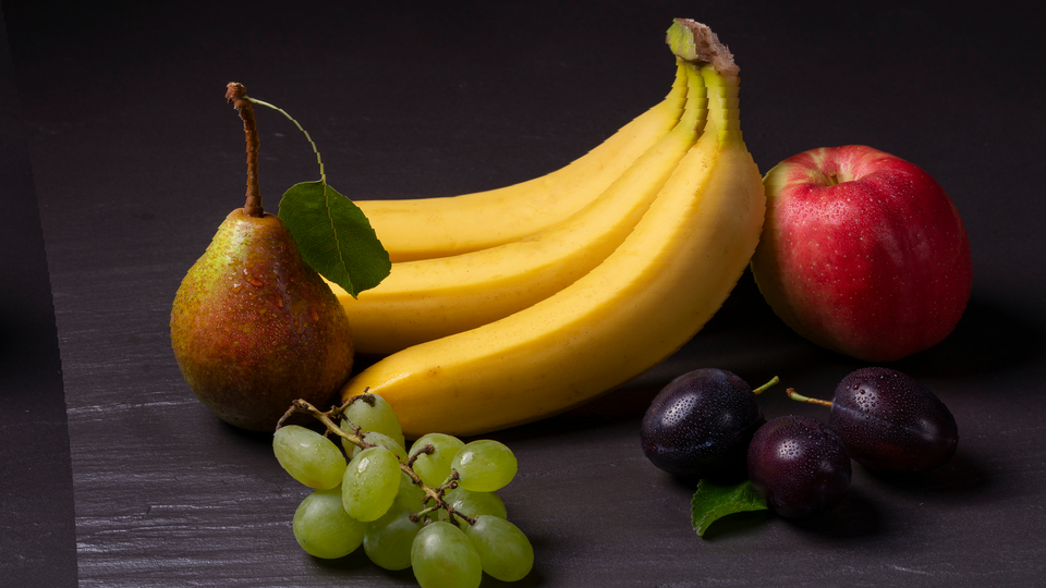
 Single-Layer Ripple — simulated result across source images.
Exercise Illustration
A description of the exercise illustration.
Learning Outcomes
Learn how amplitude, frequency, and mode interact to shape a single sine distortion layer.
Key Concepts
- Sine displacement shifts pixel read addresses
- Vert mode varies displacement per scanline; Horiz mode varies per pixel
- Amplitude controls wave depth; Frequency controls wave spacing
Video Source
A live camera feed or recorded footage with strong vertical and horizontal lines (architecture, text, grids).
Steps
- Disable Layer 2: Set Amplitude 2 (Knob 4) to 0%.
- Gentle ripple: Set Amplitude 1 (Knob 1) to about 15% and Frequency 1 (Knob 2) to about 20%. The image ripples softly with broad, slow waves.
- Increase frequency: Sweep Frequency 1 upward. The wave spacing tightens and the distortion becomes more intense.
- Switch mode: Toggle Layer 1 Mode (Switch 7) from Vert to Horiz. The distortion changes from horizontal bands rippling left/right to an accordion-like squeeze within each scanline.
- Animate: Increase Speed 1 (Knob 3) to set the wave in motion. The distortion scrolls continuously.
Settings
| Control | Value |
|---|---|
| Amplitude 1 | ~15% |
| Frequency 1 | ~20% |
| Speed 1 | ~25% |
| Amplitude 2 | 0% |
| Frequency 2 | ~12% |
| Speed 2 | 0% |
| Layer 1 Mode | Vert |
| Layer 2 Mode | Horiz |
| Cascade | L1>L2 |
| Phase Link | Off |
| Phase Lock | Free |
| Mix | 100% |
Exercise 2: Compound Cascade
 Compound Cascade — simulated result across source images.
Exercise Illustration
A description of the exercise illustration.
Learning Outcomes
Explore how two cascaded distortion layers interact to create complex warping.
Key Concepts
- Cascaded nonlinear distortion produces interference patterns
- Perpendicular modes (one Vert, one Horiz) create two-dimensional warping
- Cascade order changes the result even with identical settings
Video Source
Footage with recognizable geometry: faces, architecture, or text. The distortion is most legible when the source has clear structure to warp.
Steps
- Two perpendicular layers: Keep Layer 1 in Vert mode. Set Layer 2 Mode (Switch 8) to Horiz. Set both amplitudes to about 20% and both frequencies to about 30%.
- Observe compound warping: The image warps in two dimensions: scanlines ripple left/right and each scanline is also squeezed and stretched internally.
- Animate both: Set Speed 1 to ~20% and Speed 2 to ~15%. The two wave patterns drift at different rates, creating continuously evolving distortion.
- Swap cascade order: Toggle Cascade (Switch 9) from L1>L2 to L2>L1. Notice how the visual character changes even though the per-layer settings haven't moved.
- Phase Link: Enable Phase Link (Switch 10). Both layers now animate in lockstep (the pattern becomes more coherent and symmetrical.)
Settings
| Control | Value |
|---|---|
| Amplitude 1 | ~20% |
| Frequency 1 | ~30% |
| Speed 1 | ~20% |
| Amplitude 2 | ~20% |
| Frequency 2 | ~30% |
| Speed 2 | ~15% |
| Layer 1 Mode | Vert |
| Layer 2 Mode | Horiz |
| Cascade | L1>L2 |
| Phase Link | On |
| Phase Lock | Free |
| Mix | 100% |
Exercise 3: EarthBound Battle Screen
 EarthBound Battle Screen — simulated result across source images.
Exercise Illustration
A description of the exercise illustration.
Learning Outcomes
Recreate the iconic psychedelic battle background distortion from EarthBound.
Key Concepts
- High amplitude + moderate frequency creates intense rubber-sheet distortion
- Two layers at different speeds produce evolving kaleidoscopic patterns
- Phase Lock can freeze a striking frame for examination
Video Source
Abstract video, colorful gradients, or synthesized patterns. Bold shapes and saturated colors showcase the distortion most dramatically.
Steps
- High amplitude: Set Amplitude 1 to ~50% and Amplitude 2 to ~40%.
- Different frequencies: Set Frequency 1 to ~40% and Frequency 2 to ~60%. The mismatched frequencies produce intricate interference.
- Cross-axis modes: Set Layer 1 Mode to Vert and Layer 2 Mode to Horiz for full two-dimensional chaos.
- Animate at different speeds: Set Speed 1 to ~30% and Speed 2 to ~20%. The compound pattern evolves continuously.
- Freeze frame: Toggle Phase Lock (Switch 11) to Lock to freeze the pattern. Adjust amplitudes and frequencies to sculpt the frozen distortion.
- Wet/dry blend: Pull Mix (Fader 12) down to about 50% to blend the distorted image with the clean original for a ghostly overlay effect.
Settings
| Control | Value |
|---|---|
| Amplitude 1 | ~50% |
| Frequency 1 | ~40% |
| Speed 1 | ~30% |
| Amplitude 2 | ~40% |
| Frequency 2 | ~60% |
| Speed 2 | ~20% |
| Layer 1 Mode | Vert |
| Layer 2 Mode | Horiz |
| Cascade | L1>L2 |
| Phase Link | Off |
| Phase Lock | Free |
| Mix | 100% |
Glossary
-
Cascade: Connecting two processing stages in series so the output of one feeds the input of the other, producing compound effects.
-
Displacement: Shifting a pixel's read address by an offset, causing the image to stretch and compress rather than simply move.
-
Edge Clamping: Limiting out-of-bounds read addresses to the nearest valid pixel, preventing wrap-around artifacts.
-
Interference Pattern: A complex visual pattern that emerges when two wave fields interact, producing regions of reinforcement and cancellation.
-
Line Buffer: A block of RAM that stores one horizontal scanline of video, enabling pixel-level random access for displacement effects.
-
Phase Accumulator: A counter that advances by a fixed increment each frame, providing a continuously increasing phase offset for animation.
-
Quarter-Wave LUT: A lookup table storing one quarter of a sine cycle; the full wave is reconstructed by symmetry, saving 75% of the memory.
-
Sinusoidal Distortion: Warping an image by displacing pixel positions according to a sine function, creating smooth, periodic stretching and compression.