STIC
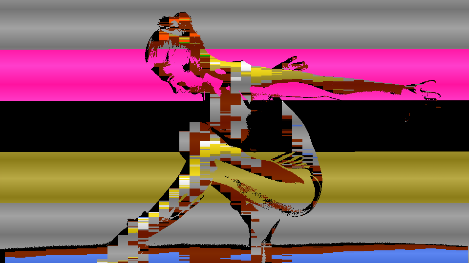
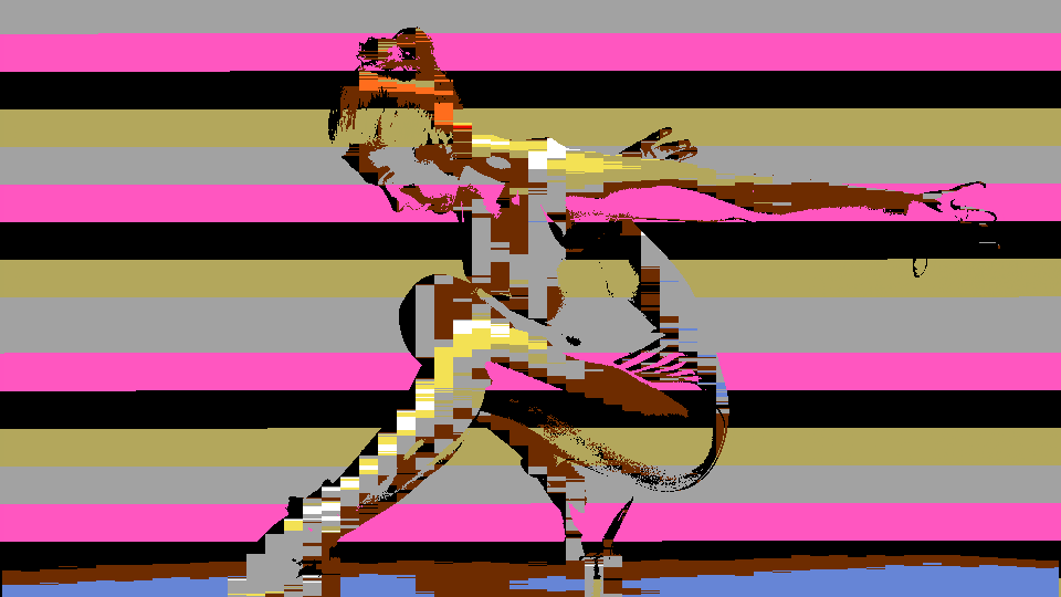 STIC rendering a live camera feed through Color Stack mode, quantizing continuous video into the Intellivision's 16-color palette with cycling background hues.
Overview
STIC is a retro video processor that recreates the display characteristics of the Intellivision's Standard Television Interface Chip, the custom graphics IC that defined the console's visual style. STIC quantizes incoming video to the Intellivision's fixed 16-color palette using Manhattan distance matching in YUV color space, then renders the result through one of two authentic display modes: Color Stack and Colored Squares.
In Color Stack mode, each tile is split into foreground and background. The foreground takes the nearest palette color to the input, while the background cycles through a rotating stack of four evenly spaced palette entries. In Colored Squares mode, each tile is subdivided into four quadrants, each independently matched to the palette, producing the ultra-blocky mosaic seen in classic Intellivision titles like Snafu. Additional features: tile grid overlay, CRT scanline dimming, and simulated sprite flicker: complete the retro illusion.
STIC uses zero block RAM. All processing is combinational logic and LUT-based palette ROM, making it one of the most resource-efficient programs in the Videomancer library.
What's In a Name?
The name STIC stands for Standard Television Interface Chip, the designation Mattel Electronics gave to the custom display processor inside the Intellivision console (officially designated AY-3-8900). The STIC was responsible for generating the console's entire video output: background tiles, sprites, and the Color Stack and Colored Squares rendering modes that STIC recreates.
Quick Start
- Send a video source into Videomancer with STIC loaded. The image is immediately quantized to 16 colors (flat, blocky, and unmistakably retro.)
- Turn Stack Hue (Knob 2) to scroll through the 16 palette entries used as the base color for the cycling background. The background tiles shift through the Intellivision rainbow.
- Increase Stack Rate (Knob 3) to speed up the Color Stack cycling. The background pattern becomes a shimmering, animated mosaic as the four-entry stack advances faster.
- Flip Mode (Switch 7) to ClrSqrs. Each tile splits into four independently colored quadrants, creating a denser, blockier mosaic reminiscent of early Intellivision puzzle games.
Parameters
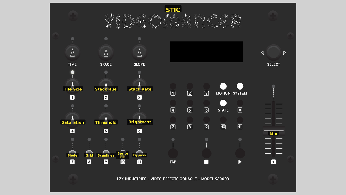 Videomancer's front panel with STIC active. Knobs 1–6 (top two rows of left cluster), Toggle switches 7–11 (bottom row of left cluster), Fader 12 (right side).
Knob 1 — Tile Size
| Property | Value |
|---|---|
| Range | 4px – 35px |
| Default | 16px |
Tile Size sets the width of each tile cell in pixels. At minimum, tiles are 4 pixels wide: small, dense blocks that preserve more spatial detail. As you turn clockwise, tiles grow up to 35 pixels wide, producing large, flat color regions. The tile height tracks the width, so tiles remain roughly square. Smaller tiles reveal more of the source image's structure through the palette quantization; larger tiles produce bold, graphic shapes.
In Colored Squares mode, each tile is subdivided into four quadrants, so a 20-pixel tile becomes four 10-pixel blocks. Smaller tile sizes in this mode can approach the source image's original detail level, just palette-quantized.
Knob 2 — Stack Hue
| Property | Value |
|---|---|
| Range | 0 – 1023 |
| Default | 0 |
Stack Hue selects the base palette entry for the Color Stack background. The knob scrolls through all 16 Intellivision colors: Black, Blue, Red, Dark Green, Tan, Green, Yellow, White, Grey, Cyan, Orange, Brown, Pink, Light Blue, Yellow-Green, and Purple. The Color Stack cycles through four palette entries spaced evenly from this base, so choosing Blue as the base produces a stack that rotates through Blue, Tan, Grey, and Pink (entries offset by 4).
Knob 3 — Stack Rate
| Property | Value |
|---|---|
| Range | 0% – 100% |
| Default | 25% |
Stack Rate controls how quickly the Color Stack advances through its four background colors. At 0%, the stack is nearly static: background tiles hold the same color for many tiles before advancing. At maximum, the stack advances every tile, creating a rapid cycling pattern across the screen. The rate is driven by a phase accumulator, so intermediate values produce smoothly varying advance intervals.
Slow stack rates with large tiles produce broad fields of alternating background color. Fast rates with small tiles create a flickering, animated texture that resembles the scrolling backgrounds of Intellivision sports games.
Knob 4 — Saturation
| Property | Value |
|---|---|
| Range | 0% – 100% |
| Default | 75% |
Saturation controls the chroma intensity of the output. At 0%, the palette-quantized image is rendered in grayscale: only the luminance differences between colors remain visible. At the default position (~75%), colors reproduce at roughly their original intensity. Turning fully clockwise pushes saturation beyond natural levels, creating vivid, oversaturated palette colors.
Knob 5 — Threshold
| Property | Value |
|---|---|
| Range | 0% – 100% |
| Default | 22% |
Threshold sets the luminance boundary between foreground and background within each tile. Pixels brighter than the threshold are rendered as the nearest palette color (foreground). Pixels darker than the threshold use the Color Stack background color instead. At 0%, nearly everything is foreground: the entire image is palette-quantized. At 100%, nearly everything becomes background, and the Color Stack pattern dominates the output.
Because Threshold operates on the input luminance before palette matching, its effect depends on the brightness of your source. A dark source with a high threshold will be almost entirely background color.
Knob 6 — Brightness
| Property | Value |
|---|---|
| Range | 0% – 100% |
| Default | 50% |
Brightness scales the luminance of the output after palette lookup and mode selection. At 0%, the output is black. At the midpoint default (~50%), palette colors display at their original brightness. Turning clockwise increases brightness, pushing the palette toward washed-out pastels. This control multiplies the Y channel of the palette-matched result, leaving chroma unchanged.
Switch 7 — Mode
| Property | Value |
|---|---|
| Off | ColorStk |
| On | ClrSqrs |
| Default | ColorStk |
Mode selects between the two STIC rendering modes. In ColorStk (Color Stack), each tile is rendered as a single foreground color chosen by palette matching, with a cycling background color from the four-entry stack. In ClrSqrs (Colored Squares), each tile is subdivided into four quadrants, and each quadrant is independently matched to the palette. Colored Squares produces denser, blockier imagery with more color variation per tile.
Switch 8 — Grid
| Property | Value |
|---|---|
| Off | Off |
| On | On |
| Default | Off |
Grid enables a dark tile boundary overlay. When set to On, a single-pixel black line is drawn at the left edge and top edge of every tile cell. The grid makes the mosaic structure explicit, adding a graph-paper quality that emphasizes the tile geometry. The grid lines are rendered at Y=64 (near-black) with neutral chroma.
Switch 9 — Scanlines
| Property | Value |
|---|---|
| Off | Off |
| On | On |
| Default | Off |
Scanlines enables CRT-style horizontal line dimming. When set to On, every other scan line is darkened, simulating the visible scan structure of a CRT television. The dimming intensity is controlled by Scan Str (Switch 11). Scanlines add an immediately recognizable retro television quality to the output.
Switch 10 — Sprite Flk
| Property | Value |
|---|---|
| Off | Off |
| On | On |
| Default | Off |
Sprite Flk (Sprite Flicker) simulates the characteristic 20 Hz sprite flicker of the Intellivision's Exec framework. When enabled, every third frame is dimmed to 50% brightness, creating a visible flicker that mimics the multiplexing technique the STIC used when more than eight sprites occupied the same horizontal line. This was one of the most recognizable visual artifacts of Intellivision gameplay.
Switch 11 — Scan Str
| Property | Value |
|---|---|
| Off | Light |
| On | Heavy |
| Default | Light |
Scan Str (Scanline Strength) controls the intensity of the scanline dimming effect when Scanlines (Switch 9) is enabled. In Light mode, each dimmed line retains 75% of its brightness. In Heavy mode, dimmed lines are reduced to 50% brightness, creating a more aggressive, deeply etched scan pattern.
Scan Str has no visible effect unless Scanlines is enabled. It only modulates the dimming depth.
Fader 12 — Mix
| Property | Value |
|---|---|
| Range | 0 – 100 |
| Default | 100 |
Mix crossfades between the dry (unprocessed) input and the wet (STIC-processed) output. At 0%, the original input passes through unchanged. At 100% (fully up, the default), the full STIC effect is applied. Intermediate positions blend the retro palette-quantized image with the original, creating a ghostly overlay where the source image's continuous tones show through the blocky palette.
Background
The Intellivision STIC
The Standard Television Interface Chip (AY-3-8900) was the heart of the Mattel Intellivision console, released in 1979. Unlike the Atari 2600's player/missile system, the STIC provided a true tile-based background display with hardware sprite support. Its most distinctive constraint was a fixed palette of just 16 colors: derived from the NTSC color space: and two unique rendering modes for background tiles: Color Stack and Colored Squares.
The Color Stack mode used a four-entry rotating register to assign background colors to tiles, producing animated color patterns without CPU intervention. The Colored Squares mode traded sprite capability for denser color information, subdividing each 8×8 tile into four 4×4 quadrant blocks, each independently colored from a subset of the palette. This produced the characteristic ultra-blocky graphics seen in games like Snafu, Checkers, and Triple Action.
Palette Quantization
STIC matches each input pixel (or tile sample) to the nearest of 16 palette colors using Manhattan distance: the sum of absolute differences across Y, U, and V channels. The distance is computed on 6-bit truncated values to reduce carry chain depth, keeping the matching logic fast enough for pixel-rate processing. All 16 distances are computed in parallel across a single clock cycle, then reduced through a tournament bracket (16→4→1) over three additional clocks to find the winning palette index.
Manhattan distance (also called L1 or taxicab distance) is computationally cheaper than Euclidean distance because it avoids multiplication and square root operations. On an iCE40 FPGA with no hardware multipliers, this is a critical advantage.
Color Stack Mechanics
The Color Stack is a four-entry rotating register that assigns background colors to tiles. The base hue selects a starting palette index, and the stack spreads four entries evenly across the palette by offsetting the index by 0, 4, 8, and 12. A phase accumulator driven by the Stack Rate parameter controls how often the stack advances. At each tile origin (the top-left corner of a new tile), the accumulator is incremented: when it overflows, the stack index advances by one. This creates spatially varying background patterns that shift across the screen.
Signal Flow
Signal Flow Notes
The pipeline has two key architectural features:
-
Parallel palette matching: All 16 Manhattan distances are computed simultaneously in Stage 2, then reduced through a tournament bracket in Stages 3–4. This parallel approach costs more LUTs but completes the nearest-color search in just three clock cycles.
-
Dual sample paths: Stage 1 maintains two independent pixel samples. The whole-tile sample (captured at each tile boundary) feeds Color Stack mode, while the quadrant sub-sample (captured at tile origin and half-cell midpoint) feeds Colored Squares mode. The mode toggle selects which sample enters the palette matching pipeline in Stage 2.
Threshold is the creative fulcrum. It doesn't gate the output: it decides which pixels get the palette-matched foreground color versus the cycling Color Stack background. Low threshold = mostly foreground (faithful to source). High threshold = mostly background (Color Stack pattern dominates).
Exercises
These exercises explore STIC's two display modes, palette cycling, and CRT simulation features. Each builds on the retro rendering pipeline to create increasingly stylized results.
Exercise 1: Color Stack Cycling
 Color Stack Cycling — simulated result across source images.
Exercise Illustration
A description of the exercise illustration.
Learning Outcomes
Learn how the Color Stack background animation interacts with the foreground palette quantization.
Key Concepts
- The Color Stack cycles four palette entries spaced evenly from the base hue
- Stack Rate controls the speed of cycling across tiles
- Threshold splits each tile into foreground (palette match) and background (stack color)
Video Source
A live camera feed or recorded footage with a mix of bright and dark regions.
Steps
- Set tile grid: Set Tile Size (Knob 1) to about 50% for medium-sized tiles. The image is immediately quantized to the 16-color palette.
- Cycle background hue: Turn Stack Hue (Knob 2) slowly through the full range. Background colors cycle through the complete Intellivision palette.
- Reveal the stack: Set Threshold (Knob 5) to about 40%. Dark regions of the image now show the Color Stack background instead of the palette-matched color.
- Animate the stack: Increase Stack Rate (Knob 3) from 0% toward maximum. The background pattern begins shimmering as the stack advances faster across tiles.
- Denser texture: Adjust Tile Size smaller. The denser tile grid makes the Color Stack cycling more visible as a fine animated texture.
Settings
| Control | Value |
|---|---|
| Tile Size | ~50% |
| Stack Hue | Blue |
| Stack Rate | ~70% |
| Saturation | ~75% |
| Threshold | ~40% |
| Brightness | ~50% |
| Mode | ColorStk |
| Grid | Off |
| Scanlines | Off |
| Sprite Flk | Off |
| Scan Str | Light |
| Mix | 100% |
Exercise 2: Colored Squares Mosaic
 Colored Squares Mosaic — simulated result across source images.
Exercise Illustration
A description of the exercise illustration.
Learning Outcomes
Explore Colored Squares mode and the grid overlay to create dense, blocky retro mosaics.
Key Concepts
- Colored Squares subdivides each tile into four independently quantized quadrants
- Grid overlay makes tile boundaries explicit
- Saturation and Brightness shape the palette appearance
Video Source
Footage with varied colors and moderate contrast: nature scenes, painted surfaces, or abstract patterns work well.
Steps
- Quad subdivide: Switch Mode (Switch 7) to ClrSqrs. Each tile now shows four independent color blocks instead of one.
- Show tile grid: Enable Grid (Switch 8). Dark lines appear at every tile boundary, giving the image a graph-paper quality.
- Shrink the tiles: Reduce Tile Size (Knob 1) to about 30%. The quadrants become smaller and denser, revealing more of the source image's color structure through the palette.
- Vivid palette: Push Saturation (Knob 4) fully clockwise. The palette colors become vivid and oversaturated (pure retro gameplay aesthetic.)
- Maximize foreground: Lower Threshold (Knob 5) toward 0% so nearly all pixels are palette-matched foreground, maximizing the Colored Squares mosaic.
Settings
| Control | Value |
|---|---|
| Tile Size | ~30% |
| Stack Hue | Red |
| Stack Rate | ~50% |
| Saturation | 100% |
| Threshold | ~10% |
| Brightness | ~50% |
| Mode | ClrSqrs |
| Grid | On |
| Scanlines | Off |
| Sprite Flk | Off |
| Scan Str | Light |
| Mix | 100% |
Exercise 3: Full Retro CRT Simulation
 Full Retro CRT Simulation — simulated result across source images.
Exercise Illustration
A description of the exercise illustration.
Learning Outcomes
Combine palette quantization with scanlines, sprite flicker, and grid to simulate the complete Intellivision display experience.
Key Concepts
- Scanlines and sprite flicker are multiplicative dimming effects applied after palette processing
- Scan Str controls scanline depth (75% vs 50%)
- Sprite flicker dims every third frame to simulate hardware multiplexing
Video Source
High-contrast footage with clear shapes: silhouettes, graphic patterns, or gameplay footage if available.
Steps
- Bold tile grid: Set Tile Size (Knob 1) to about 60% for large, bold tiles. Enable Grid (Switch 8) to see tile boundaries.
- Add scanlines: Enable Scanlines (Switch 9). Every other scan line darkens, adding CRT texture. Toggle Scan Str (Switch 11) between Light and Heavy to compare the two dimming depths.
- Sprite flicker: Enable Sprite Flk (Switch 10). The image begins flickering at roughly 20 Hz as every third frame dims. This is the most recognizable Intellivision visual artifact.
- Background animation: Set Stack Rate (Knob 3) to about 30% for slow background cycling. Lower Threshold (Knob 5) to about 50% so some background tiles show the cycling stack.
- Darken the display: Reduce Brightness (Knob 6) slightly below 50% to darken the overall image, enhancing the CRT appearance.
- Ghost the original: Slowly sweep Mix (Fader 12) down to see the original image ghost through the retro rendering.
Settings
| Control | Value |
|---|---|
| Tile Size | ~60% |
| Stack Hue | Black |
| Stack Rate | ~30% |
| Saturation | ~75% |
| Threshold | ~50% |
| Brightness | ~40% |
| Mode | ColorStk |
| Grid | On |
| Scanlines | On |
| Sprite Flk | On |
| Scan Str | Heavy |
| Mix | 100% |
Glossary
-
Color Stack: A four-entry rotating register in the STIC that cyclically assigns background colors to tiles, producing animated color patterns without CPU intervention.
-
Colored Squares: A STIC rendering mode that subdivides each 8×8 tile into four 4×4 quadrant blocks, each independently colored from the palette.
-
Manhattan Distance: The sum of absolute differences between two points across all dimensions; used here to match pixels to the nearest palette color in YUV space.
-
Palette Quantization: Reducing a continuous range of colors to a fixed set of discrete entries by mapping each pixel to its nearest palette match.
-
Phase Accumulator: A counter that adds a fixed increment each cycle and triggers an event when it overflows; used here to control the Color Stack advance rate.
-
Sample and Hold: Capturing a signal value at a specific moment and holding it constant until the next sample point; used in tile rendering to hold one color across the entire tile width.
-
Scanline Dimming: Darkening alternating horizontal lines to simulate the visible raster structure of a CRT display.
-
Sprite Flicker: A visual artifact caused by hardware sprite multiplexing, where sprites are displayed on alternating frames to exceed hardware limits, producing a characteristic 20–30 Hz flicker.
-
STIC: Standard Television Interface Chip (AY-3-8900); the custom display processor in the Mattel Intellivision console.
-
Tile: A fixed-size rectangular cell in a tile-based display system; the fundamental unit of background rendering in the STIC.
-
Tournament Bracket Reduction: A parallel comparison tree that finds the minimum of N values in O(log N) stages by comparing pairs and advancing winners.