Elastica
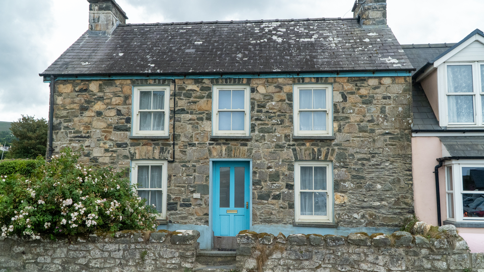 Elastica applying sine-wave horizontal displacement to create rippling, Scanimate-style warp animation across the video frame.
Overview
Elastica is a per-scanline horizontal displacement engine inspired by the Scanimate, the legendary analog computer animation system of the 1970s. Its core trick is simple: each line of the image is shifted left or right by an amount determined by a programmable waveshape. The result is a fluid bowing, rippling, shearing, or stacking of the picture that feels organic and alive: the visual equivalent of dragging your fingers across wet ink.
Elastica generates its displacement pattern using a direct digital synthesis (DDS) phase accumulator that advances once per scanline. Four waveshapes: sine, triangle, sawtooth, and square: create different flavors of distortion. A second DDS handles vertical squeeze and stretch, and the two generators can be cross-modulated for complex two-dimensional warping. When animation is enabled, the phase scrolls continuously, recreating the signature Scanimate "ripple crawl" that made the original hardware so mesmerizing.
Start with a sine wave and low amplitude. Even subtle displacement transforms static video into something that seems to breathe.
What's In a Name?
The name Elastica evokes the mathematical concept of the elastica curve: the shape a flexible rod takes when bent. It also carries a direct, tactile meaning: the image becomes elastic, stretching and compressing as if printed on a rubber sheet. The Scanimate connection adds a layer of history: Elastica brings the spirit of analog computer animation into a modern FPGA pipeline.
Quick Start
- Set H Amplitude (Knob 2) to about 50%. The image bows into a smooth sine wave pattern: scanlines shift left and right, bending the picture like a funhouse mirror.
- Sweep H Frequency (Knob 1) from low to high. Low frequencies produce wide, sweeping bends; high frequencies create tight ripples.
- Toggle Animate (Switch 11) to On and adjust Anim Speed (Knob 6). The warp pattern scrolls vertically, creating the classic Scanimate ripple crawl.
Parameters
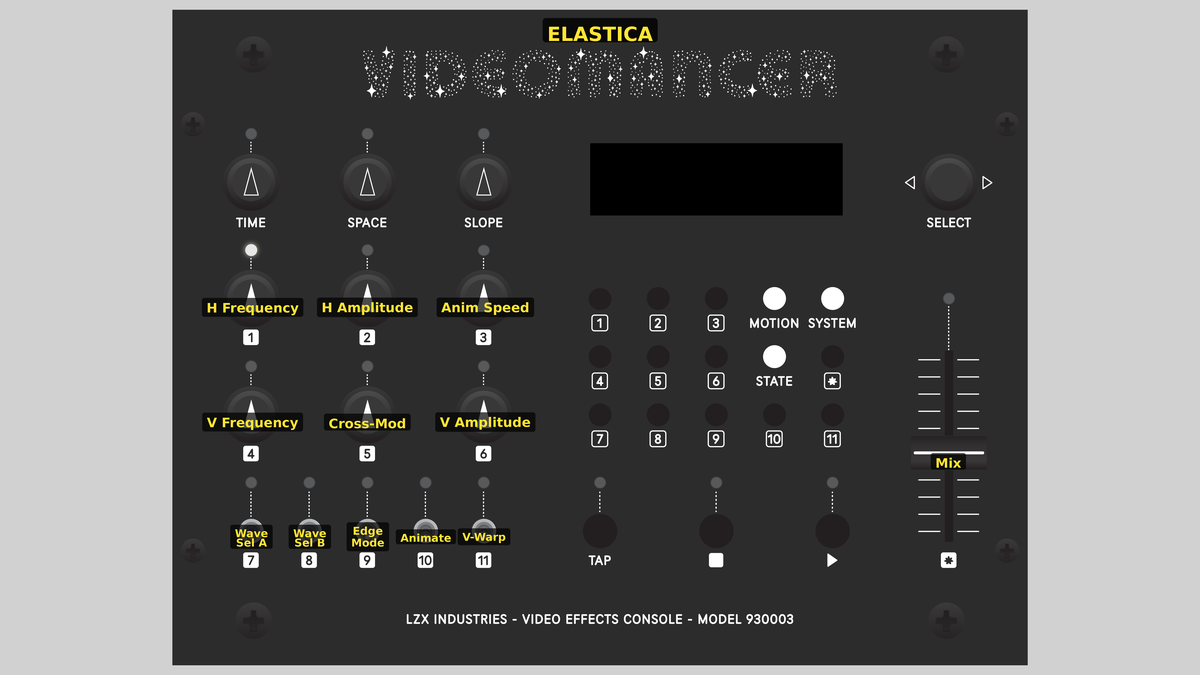 Videomancer's front panel with Elastica active. Knobs 1–6 (top two rows of left cluster), Toggle switches 7–11 (bottom row of left cluster), Fader 12 (right side).
Knob 1 — H Frequency
| Property | Value |
|---|---|
| Range | 0.0% – 100.0% |
| Default | 25.0% |
H Frequency controls the spatial frequency of the horizontal displacement wave. At 0%, the wave completes very few cycles across the frame height, producing a single wide bend. As the value increases, the wave completes more cycles, creating tighter and more numerous ripples. At 100%, the displacement pattern is packed with rapid oscillations. The DDS accumulator advances once per scanline, so this parameter directly controls how many wave cycles fit within each field.
Knob 2 — H Amplitude
| Property | Value |
|---|---|
| Range | 0.0% – 100.0% |
| Default | 0.0% |
H Amplitude controls the maximum horizontal pixel displacement. At 0%, there is no displacement: the image passes through unchanged. As the value increases, scanlines shift farther left and right, creating increasingly dramatic warping. At 100%, displacement reaches the full line buffer width, producing extreme distortion where large portions of the image may be pushed off-screen.
At high amplitudes with Edge Mode set to Clamp, displaced pixels that fall outside the active area are replaced with black. Set Edge Mode to Wrap to avoid black borders and instead wrap the image around.
Knob 3 — Cross-Mod
| Property | Value |
|---|---|
| Range | 0.0% – 100.0% |
| Default | 0.0% |
Cross-Mod controls how much the vertical wave modulates the horizontal displacement amplitude. At 0%, the horizontal warp is uniform from top to bottom. As Cross-Mod increases, the vertical wave's absolute value multiplies into the horizontal amplitude, creating regions of strong and weak displacement that vary vertically. At 100%, the cross-modulation is at full intensity, producing complex two-dimensional warping patterns. This is the key to Elastica's most intricate distortions.
Knob 4 — V Frequency
| Property | Value |
|---|---|
| Range | 0.0% – 100.0% |
| Default | 12.5% |
V Frequency controls the spatial frequency of the vertical warp wave. This DDS also advances once per scanline. At low values, the vertical wave is slow and sweeping. At high values, it cycles rapidly. The vertical wave serves two purposes: it drives vertical squeeze/stretch (when V-Warp is enabled) and provides the modulation source for Cross-Mod.
Knob 5 — V Amplitude
| Property | Value |
|---|---|
| Range | 0.0% – 100.0% |
| Default | 0.0% |
V Amplitude controls the intensity of the vertical warp effect. At 0%, there is no vertical distortion. As the value increases, lines are selectively skipped based on the vertical wave's amplitude, creating a squeeze-and-stretch effect. Skipped lines are replaced with black. At high values, large sections of the image collapse while others expand, producing accordion-like vertical compression.
V Amplitude has no visible effect unless V-Warp (Switch 9) is turned On.
Knob 6 — Anim Speed
| Property | Value |
|---|---|
| Range | 0.0% – 100.0% |
| Default | 25.0% |
Anim Speed has two behaviors depending on the state of Animate (Switch 11). When Animate is On, this knob controls the scroll speed of the displacement pattern: the phase accumulator advances each frame, and the speed setting determines how far it moves per frame. Low values produce a slow, hypnotic drift; high values create rapid scrolling. When Animate is Off, this knob sets a static phase offset, letting you manually position the wave pattern.
Switch 7 — Wave Sel A
| Property | Value |
|---|---|
| Off | Off |
| On | On |
| Default | Off |
Wave Sel A is the low bit of the two-bit waveshape selector. Combined with Wave Sel B (Switch 8), it selects one of four displacement waveshapes. See Toggle Group Notes below.
Switch 8 — Wave Sel B
| Property | Value |
|---|---|
| Off | Off |
| On | On |
| Default | Off |
Wave Sel B is the high bit of the two-bit waveshape selector. Combined with Wave Sel A (Switch 7), it selects one of four displacement waveshapes. See Toggle Group Notes below.
Switch 9 — V-Warp
| Property | Value |
|---|---|
| Off | Off |
| On | On |
| Default | Off |
V-Warp enables or disables the vertical warp effect. When Off, the vertical DDS still runs (and still feeds Cross-Mod), but no lines are skipped. When On, the vertical wave's amplitude is compared against a threshold, and lines that exceed it are replaced with black, producing vertical squeeze and stretch.
Switch 10 — Edge Mode
| Property | Value |
|---|---|
| Off | Clamp |
| On | Wrap |
| Default | Clamp |
Edge Mode selects how out-of-range displaced pixels are handled. In Clamp mode, pixels pushed beyond the active line boundaries are replaced with black, creating dark margins at the edges of the warp. In Wrap mode, the read address wraps around modularly, so pixels pushed off one edge reappear at the other. Wrap mode produces a seamless, tiling distortion with no black borders.
Switch 11 — Animate
| Property | Value |
|---|---|
| Off | Off |
| On | On |
| Default | On |
Animate enables or disables continuous phase scrolling of the displacement pattern. When On, the animation DDS advances each frame, and Anim Speed (Knob 6) controls the scroll rate. The warp pattern crawls vertically through the image: this is the signature Scanimate ripple effect. When Off, the phase is static and Anim Speed sets a fixed phase offset instead.
Wave Sel A (Switch 7) and Wave Sel B (Switch 8) form a two-bit binary selector that chooses the displacement waveshape:
| Wave Sel A | Wave Sel B | Waveshape |
|---|---|---|
| Off | Off | Sine — smooth, organic bowing |
| On | Off | Triangle — angular, zigzag distortion |
| Off | On | Sawtooth — asymmetric shearing ramp |
| On | On | Square — hard alternating displacement |
Each waveshape creates a fundamentally different character of distortion. Sine is the most natural, triangle is sharper at the peaks, sawtooth produces a persistent lean, and square creates hard-edged stacking where scanlines jump between two fixed offsets.
Sine is the classic Scanimate shape. Start there. Triangle and sawtooth add edge and asymmetry. Square is dramatic: entire blocks of the image shift sideways like a deck of cards.
:::
Fader 12 — Mix
| Property | Value |
|---|---|
| Range | 0 – 100 |
| Default | 100 |
Mix is a wet/dry crossfade between the original unwarped input and the displaced output. At 0%, the original signal passes through unchanged. At 100%, the fully warped signal is output. Intermediate values blend the two, creating a ghostly double-exposure of the warped and unwarped images. Each channel (Y, U, V) is interpolated independently.
Background
Scanimate and Analog Video Animation
The Scanimate was an analog computer built by Computer Image Corporation in the late 1960s. It manipulated video signals in real time by applying mathematical transformations to the deflection circuits of a CRT monitor, then re-scanning the distorted image with a camera. The result was fluid, organic animation of text and graphics: the kind you'd see on 1970s TV show intros, news titles, and advertisements. Scanimate's signature move was per-scanline horizontal displacement: each line of the raster could be independently shifted left or right, creating bowing, rippling, and flowing effects that felt hand-animated.
Elastica recreates this fundamental technique digitally. Instead of bending electron beams, it reads pixels from a line buffer at displaced addresses. The math is the same; the medium is different.
Direct Digital Synthesis
Elastica's warp patterns are generated by a DDS phase accumulator: a counter that advances by a programmable step (the "tuning word") on each clock event. The upper bits of the accumulator address a waveshape function. Because the accumulator wraps naturally at its word size, the resulting waveshape is inherently periodic. The frequency is set by the tuning word: larger steps mean faster cycling.
Elastica uses two independent DDS generators. The horizontal DDS advances once per scanline to generate the spatial displacement pattern. The animation DDS advances once per frame to scroll the pattern over time. Their outputs are summed to produce the final phase, so animation adds a continuously changing offset to the spatial warp.
Dual-Bank Line Buffer
The displacement engine needs to read pixels at arbitrary horizontal positions within the current scanline while simultaneously writing new pixels. Elastica solves this with a ping-pong buffer: two banks of block RAM that alternate roles each line. While one bank captures incoming pixels, the other serves displaced reads. The mirror_delay_line_slv module manages this swap, providing single-cycle random-access reads from 2048-pixel banks.
Signal Flow
Signal Flow Notes
Two key architectural features define Elastica's behavior:
-
Line-rate vs. pixel-rate processing. The warp generator runs at the scanline rate: it computes one displacement value per line, then holds it constant across all pixels in that line. Every pixel on a given scanline is displaced by the same amount. This is fundamental to the Scanimate aesthetic: the distortion is smooth vertically (varying line by line) but uniform horizontally within each line.
-
Cross-modulation path. The vertical wave's absolute value feeds a multiply chain that modulates the horizontal amplitude. When Cross-Mod is zero, horizontal amplitude is uniform. When Cross-Mod is high, the vertical wave creates zones of strong and weak horizontal displacement, producing two-dimensional warping from two one-dimensional generators.
The vertical warp has a dual role. Even with V-Warp (Switch 9) off, the vertical DDS still runs and feeds Cross-Mod. Turn V-Warp off but Cross-Mod up to get 2D warping without line skipping.
Exercises
These exercises progress from basic displacement through animation and cross-modulation, building toward complex 2D warping.
Exercise 1: Classic Scanimate Ripple
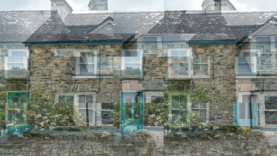
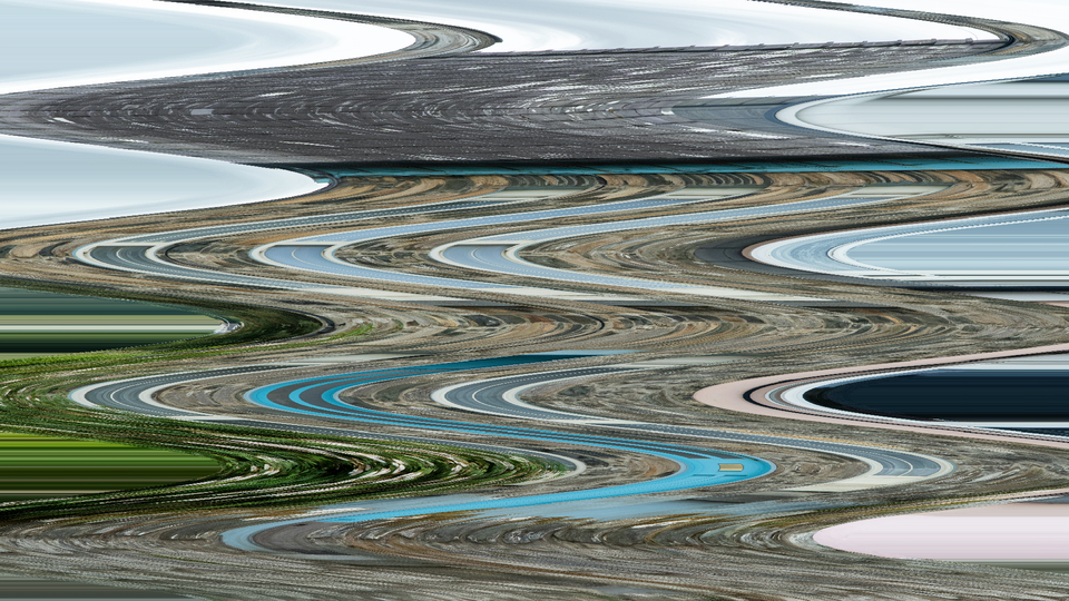 Classic Scanimate Ripple — simulated result across source images.
Exercise Illustration
A description of the exercise illustration.
Learning Outcomes
Recreate the signature horizontal ripple effect of the Scanimate analog animation system.
Key Concepts
- DDS phase accumulator generates periodic displacement
- Sine waveshape produces smooth, organic bowing
- Animation scrolls the displacement pattern over time
Video Source
A live camera feed or recorded footage with strong vertical lines or text.
Steps
- Initial displacement: Set H Amplitude (Knob 2) to about 40%. The image bows gently into a sine wave.
- Tune the ripple: Adjust H Frequency (Knob 1) until you see 3–4 complete wave cycles across the frame height.
- Start animation: Toggle Animate (Switch 11) to On. Set Anim Speed (Knob 6) to about 25%. The wave pattern crawls upward through the image.
- Deepen the warp: Slowly increase H Amplitude to see the distortion deepen. Notice how vertical lines in the source bend and flow.
- Compare waveshapes: Change waveshapes: set Wave Sel A (Switch 7) to On for triangle. Compare the sharper peaks with the smooth sine.
Settings
| Control | Value |
|---|---|
| H Frequency | ~40% |
| H Amplitude | ~40% |
| Cross-Mod | 0% |
| V Frequency | ~25% |
| V Amplitude | 0% |
| Anim Speed | ~25% |
| Wave Sel A | Off |
| Wave Sel B | Off |
| V-Warp | Off |
| Edge Mode | Clamp |
| Animate | On |
| Mix | 100% |
Exercise 2: Cross-Modulated 2D Warp
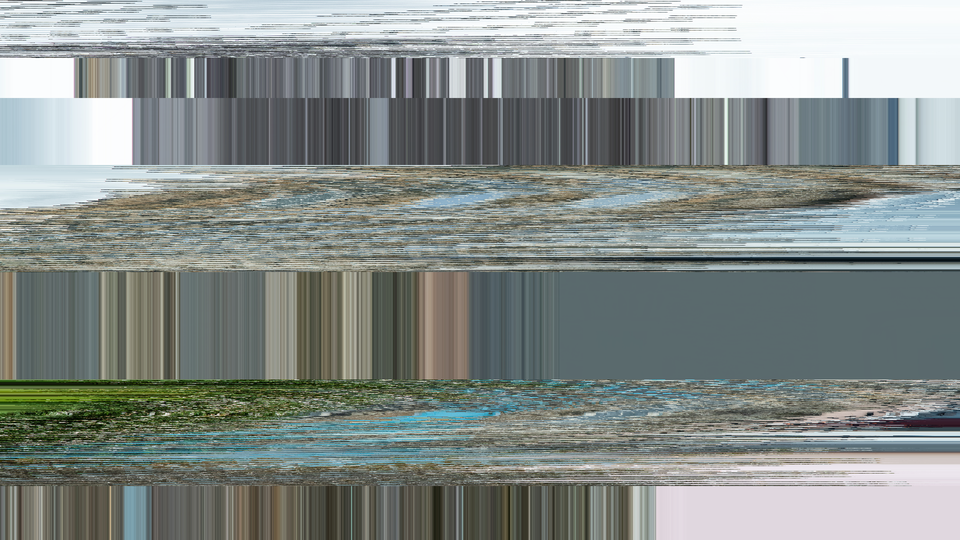 Cross-Modulated 2D Warp — simulated result across source images.
Exercise Illustration
A description of the exercise illustration.
Learning Outcomes
Combine horizontal and vertical generators for complex two-dimensional warping.
Key Concepts
- Cross-modulation multiplies vertical wave into horizontal amplitude
- V-Warp adds line skipping for vertical squeeze/stretch
- Wrap edge mode eliminates black borders
Video Source
Footage with large geometric shapes or a test pattern with both vertical and horizontal lines.
Steps
- Sine baseline: Start from Exercise 1's sine ripple (H Amplitude ~40%, moderate frequency).
- Engage cross-mod: Increase Cross-Mod (Knob 3) to about 60%. The horizontal displacement becomes stronger in some vertical regions and weaker in others.
- Shape the zones: Adjust V Frequency (Knob 4) to change where the strong/weak zones fall. Low V Frequency creates broad zones; high V Frequency creates rapid alternation.
- Vertical compression: Enable V-Warp (Switch 9) and increase V Amplitude (Knob 5) to about 30%. Lines begin to skip, creating vertical compression banding.
- Seamless tiling: Switch Edge Mode (Switch 10) to Wrap. The black borders vanish, replaced by a seamlessly tiling distortion.
Settings
| Control | Value |
|---|---|
| H Frequency | ~35% |
| H Amplitude | ~40% |
| Cross-Mod | ~60% |
| V Frequency | ~30% |
| V Amplitude | ~30% |
| Anim Speed | ~20% |
| Wave Sel A | Off |
| Wave Sel B | Off |
| V-Warp | On |
| Edge Mode | Wrap |
| Animate | On |
| Mix | 100% |
Exercise 3: Waveshape Exploration
 Waveshape Exploration — simulated result across source images.
Exercise Illustration
A description of the exercise illustration.
Learning Outcomes
Compare all four waveshapes and discover how each transforms the image differently.
Key Concepts
- Four waveshapes: sine, triangle, sawtooth, square
- Waveshape selection is a 2-bit binary code (Wave Sel A + B)
- Each shape creates a fundamentally different distortion character
Video Source
A bold graphic or title card with strong horizontal text.
Steps
- Set the canvas: Set H Amplitude (Knob 2) to ~50% and H Frequency (Knob 1) to ~30%. Disable animation (Animate Switch 11 to Off).
- Sine wave: Both wave switches Off (Sine): observe the smooth, organic bowing. Text curves gracefully.
- Triangle peaks: Set Wave Sel A (Switch 7) to On (Triangle): the peaks sharpen. Bowing becomes angular, like zigzag folds.
- Sawtooth shear: Set Wave Sel A to Off, Wave Sel B (Switch 8) to On (Sawtooth): the distortion becomes asymmetric. One side of each bend is gradual, the other is abrupt.
- Square stacking: Set both switches On (Square): scanlines jump between two fixed offsets. The image splits into hard-edged horizontal bands that slide sideways like a shuffled deck of cards.
- Animate each shape: Enable Animate and sweep through Anim Speed with each waveshape to see how animation character changes.
Settings
| Control | Value |
|---|---|
| H Frequency | ~30% |
| H Amplitude | ~50% |
| Cross-Mod | 0% |
| V Frequency | ~25% |
| V Amplitude | 0% |
| Anim Speed | ~25% |
| Wave Sel A | varies |
| Wave Sel B | varies |
| V-Warp | Off |
| Edge Mode | Clamp |
| Animate | Off |
| Mix | 100% |
Glossary
-
Cross-Modulation: Using one oscillator's output to control the amplitude of another, creating complex patterns from simple waveforms.
-
DDS (Direct Digital Synthesis): A technique for generating periodic waveforms by incrementing a phase accumulator and mapping the result through a waveshape function.
-
Displacement: Shifting pixel read positions horizontally, causing the image to appear bent or distorted.
-
Edge Clamping: Replacing out-of-range displaced pixels with black, creating dark margins at the warp boundaries.
-
Edge Wrapping: Using modular addressing so displaced pixels that exit one edge reappear at the other, creating seamless tiling distortion.
-
Line Buffer: Block RAM that stores one complete scanline of video, enabling random-access reads at displaced horizontal positions.
-
Phase Accumulator: A counter that advances by a programmable step each clock event; its upper bits drive waveshape generation.
-
Ping-Pong Buffer: A dual-bank memory arrangement where one bank captures incoming data while the other serves reads, alternating roles each cycle.
-
Scanimate: An analog computer animation system (1969–1990s) that manipulated CRT deflection to create real-time video animation effects.
-
Tuning Word: The step size added to a DDS phase accumulator each cycle; larger tuning words produce higher frequencies.