Stipple
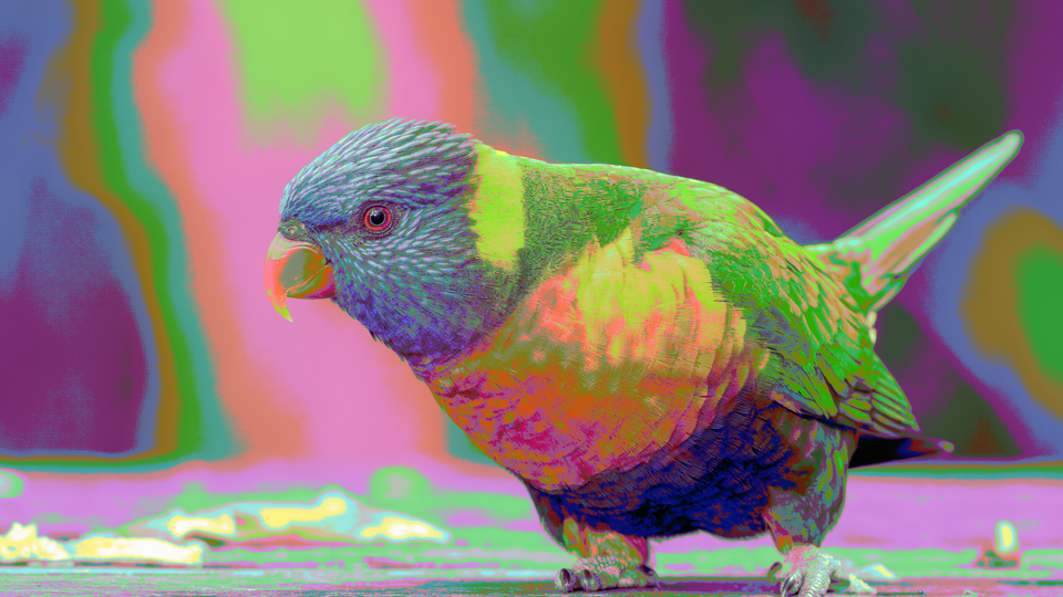 Stipple mapping live video through the Game Boy's four-shade green palette with 4×4 Bayer dithering and scanline emulation.
Overview
Stipple is a retro palette quantizer that maps incoming video to the exact color palettes of eight classic computing platforms. It reduces the full-color video stream to a handful of carefully chosen colors: four shades of green for the Game Boy, stark black and white for the original Macintosh, or the rich sixteen-color palettes of the NES, C64, and Amiga. The magic is in the dithering: an ordered pattern of dots that tricks the eye into perceiving more colors than actually exist.
Stipple chains brightness and contrast adjustment, Bayer or noise dithering, palette quantization, saturation control, pixel doubling, and scanline emulation into a single pipeline. At minimum settings, Stipple can apply a subtle palette restriction. At maximum, it transforms video into something that looks like it was rendered on vintage hardware: chunky pixels, limited colors, and the unmistakable stipple patterns of early computer graphics.
Dithering is the heart of Stipple. Without it, palette quantization produces harsh color banding. With it, the eye blends neighboring pixels into intermediate shades, conjuring colors the palette doesn't actually contain.
What's In a Name?
The name Stipple refers to the drawing technique of creating tonal gradations using patterns of small dots. In digital graphics, stippling is synonymous with ordered dithering: the technique at the core of this program. Classic platforms like the Game Boy and Macintosh relied heavily on stipple patterns to simulate shading with their severely limited color palettes.
Quick Start
- Turn Palette (Knob 1) to select a platform. Start with the Game Boy palette (position 0) (its four green shades make dithering patterns easy to see.)
- Set Dither Size (Knob 2) to its maximum. The ordered dot pattern appears across the image, breaking smooth gradients into a grid of stippled points.
- Increase Dither Amt (Knob 3) to strengthen the dithering. The stipple pattern becomes more prominent and the transitions between palette colors soften.
- Enable Scanlines (Switch 8) and Pixel Dbl (Switch 7) for the full retro CRT look. The image now resembles output from a vintage television.
Parameters
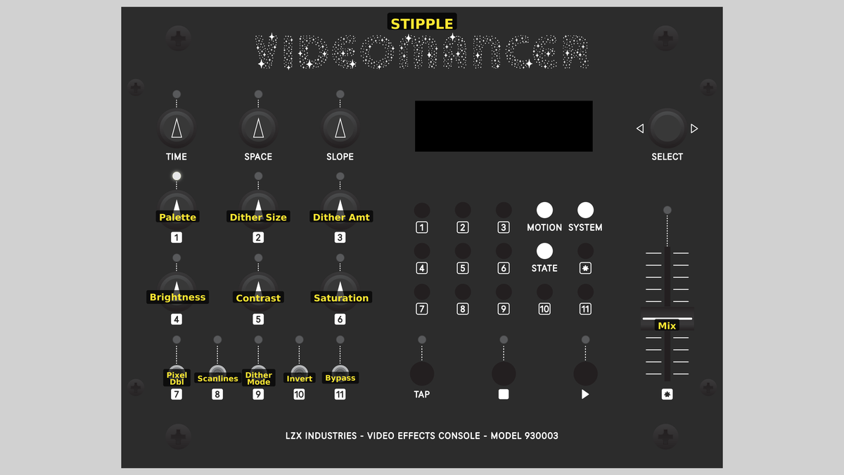 Videomancer's front panel with Stipple active. Knobs 1–6 (top two rows of left cluster), Toggle switches 7–11 (bottom row of left cluster), Fader 12 (right side).
Knob 1 — Palette
| Property | Value |
|---|---|
| Range | 0 – 7 |
| Default | 0 |
Palette selects one of eight classic computing platform color palettes. Each palette contains the exact RGB values of its historical source, pre-converted to YUV at synthesis time. The eight platforms, in order from 0 to 7: Game Boy (4 green shades), CGA Mode 4 (black, magenta, cyan, white), Macintosh (black and white), NES (16 colors), EGA (16 colors), C64 (16 colors), Amiga OCS (16 colors), and Amstrad CPC (16 colors).
Palettes with fewer native colors repeat entries to fill all sixteen slots. The Game Boy's four shades each repeat four times; the Macintosh's two colors each repeat eight times.
Smaller palettes produce stronger quantization artifacts, which makes dithering more visually important. The Macintosh palette: pure black and white: benefits the most from ordered dithering.
Knob 2 — Dither Size
| Property | Value |
|---|---|
| Range | 0 – 3 |
| Default | 1 |
Dither Size controls the spatial scale of the dither matrix. It selects between four matrix sizes: None (dithering disabled), 2×2, 4×4, and 8×8. Larger matrices produce finer stipple patterns with more threshold levels, creating smoother apparent gradations. The 8×8 Bayer matrix provides 64 distinct threshold levels, while the 2×2 matrix provides only 4.
When set to None, the Bayer address is fixed at zero and dithering has no spatial variation, regardless of the Dither Amt setting.
Knob 3 — Dither Amt
| Property | Value |
|---|---|
| Range | 0.0% – 100.0% |
| Default | 50.0% |
Dither Amt controls the strength of the dithering offset applied before quantization. At 0%, no dither offset is added, and the quantizer produces hard color boundaries. As the amount increases, the dither pattern pushes pixel values further across quantization thresholds, producing more visible stipple texture. At 100%, the dither offset reaches its maximum range, creating bold dot patterns.
The offset is computed as a shift-and-add approximation that scales the centered Bayer value (−32 to +31) by the amount parameter.
Knob 4 — Brightness
| Property | Value |
|---|---|
| Range | 0.0% – 100.0% |
| Default | 50.0% |
Brightness applies a DC offset to the luminance channel after contrast scaling. At 50% (center position), there is no offset. Turning counterclockwise darkens the image; turning clockwise brightens it. Brightness adjustment occurs before dithering and quantization, so it shifts which palette colors the quantizer selects.
Use Brightness to bias the image toward the dark or light end of a palette. On the Game Boy palette, a slight brightness increase shifts the entire image toward the lighter greens.
Knob 5 — Contrast
| Property | Value |
|---|---|
| Range | 0.0% – 100.0% |
| Default | 50.0% |
Contrast scales the luminance channel before brightness offset. The scaling uses a shift-and-add approximation of the top three bits of the control value. At low contrast, the luminance range compresses toward mid-gray, reducing the number of palette colors that get used. At high contrast, the luminance range stretches, engaging the full palette and producing punchier color boundaries.
Knob 6 — Saturation
| Property | Value |
|---|---|
| Range | 0.0% – 100.0% |
| Default | 50.0% |
Saturation scales the chrominance (U and V) channels of the palette output. The control quantizes to four levels: fully desaturated (gray-scale), half saturation, normal (100%), and oversaturated (150%). At minimum, all palette colors collapse to their luminance-equivalent grays. At maximum, palette colors become more vivid than their historical originals.
On monochrome palettes like the Macintosh (black and white) and Game Boy (shades of green), the saturation control has no visible effect at the lower two levels because the palette colors are already near the neutral axis.
Switch 7 — Pixel Dbl
| Property | Value |
|---|---|
| Off | Off |
| On | On |
| Default | Off |
Pixel Dbl enables horizontal pixel doubling by holding each palette output value for two consecutive pixels. The visible result is chunkier, wider pixels that resemble the low horizontal resolution of vintage displays. When off, each pixel is independently quantized. Pixel doubling is applied after palette lookup and saturation scaling, so it operates on final palette colors.
Switch 8 — Scanlines
| Property | Value |
|---|---|
| Off | Off |
| On | On |
| Default | Off |
Scanlines darkens every other horizontal line to 50% brightness, simulating the visible raster lines of a CRT monitor. This effect is applied after pixel doubling, so both effects can combine for an authentic retro display look. When off, all lines are rendered at full brightness.
Switch 9 — Dither Mode
| Property | Value |
|---|---|
| Off | Bayer |
| On | Noise |
| Default | Bayer |
Dither Mode selects between two dithering algorithms. In the Bayer position, the dither pattern is a fixed 8×8 ordered matrix that produces a regular, repeating stipple grid. In the Noise position, a linear feedback shift register (LFSR) generates pseudo-random noise values instead, producing a texture resembling film grain. Bayer dithering creates structured, geometric patterns; noise dithering creates organic, random textures.
Switch 10 — Invert
| Property | Value |
|---|---|
| Off | Off |
| On | On |
| Default | Off |
Invert applies a luminance inversion after brightness and contrast adjustment, before dithering. The entire tonal scale flips: blacks become white, whites become black, and all intermediate values reverse. Because inversion occurs upstream of the dither and quantize stages, it changes which palette colors the quantizer selects for each region of the image.
Switch 11 — Dith Phase
| Property | Value |
|---|---|
| Off | Off |
| On | On |
| Default | Off |
Dith Phase shifts the Bayer dither matrix diagonally by XOR-ing the matrix address with a constant. This offsets the stipple pattern by several pixels in both axes, producing a different spatial arrangement of the same dither thresholds. The visual effect is subtle: the dot pattern shifts position without changing its overall character. When using Noise mode, this toggle has no effect because the LFSR output is not address-based.
Fader 12 — Mix
| Property | Value |
|---|---|
| Range | 0.0% – 100.0% |
| Default | 100.0% |
Mix crossfades between the dry (unprocessed) input and the wet (palette-quantized) output using a four-clock interpolator. At 0%, the original video passes through unchanged. At 100%, the full Stipple effect is applied. Intermediate positions blend the two, which can soften the palette restriction into a subtle color cast rather than hard quantization.
Background
Palette quantization
Palette quantization is the process of mapping a full-range image to a fixed set of colors. Early computers had no choice: hardware constraints limited them to a tiny color palette. The Game Boy's screen could display exactly four shades of green. The Commodore 64 had sixteen fixed colors. Artists working within these limits developed visual languages built on careful color choice and clever dithering.
Stipple stores all eight palettes as 128 constant RGB entries (8 platforms × 16 colors each), pre-converted to YUV at synthesis time using BT.601 coefficients. The input luminance, after contrast and brightness adjustment, is quantized to a 4-bit index (0–15) that addresses the selected palette's color table. The result is a direct color lookup: no interpolation, no blending, just a hard snap to the nearest palette entry.
Ordered dithering
- Ordered dithering* uses a repeating threshold matrix: typically a *Bayer matrix: to distribute quantization error spatially. Each pixel position in the matrix has a different threshold. When a pixel's value falls near a quantization boundary, the local threshold determines which side it lands on. The result is a structured stipple pattern where dots cluster into regular geometric arrangements.
The 8×8 Bayer matrix provides 64 distinct threshold levels: 64 different transition points between any two palette colors: yielding much smoother apparent gradients than the palette's actual color count would suggest. Smaller matrices (2×2 or 4×4) have fewer thresholds and produce coarser patterns.
Retro display emulation
Stipple's pixel doubling and scanline features reproduce the visual characteristics of vintage CRT displays. Pixel doubling halves the effective horizontal resolution by holding each palette output for two consecutive pixels, mimicking the chunky rectangular pixels of low-resolution display modes. Scanline emulation darkens every other line to 50% brightness, recreating the visible horizontal gaps between raster lines on a CRT. Together, these two features transform the clean, sharp digital output into something that evokes the warm, textured look of old televisions and monitors.
Signal Flow
Signal Flow Notes
The pipeline runs entirely on the luminance channel until palette lookup. Input Y is contrast-scaled and brightness-offset in two pipelined stages, then optionally inverted. The adjusted Y value enters the dither-and-quantize section, where a Bayer matrix value (or LFSR noise) is scaled by the dither amount and added as an offset before the value is divided into a 4-bit palette index. That index addresses one of the eight platform color tables, producing a full YUV triplet from the palette ROM. The U and V channels of the input video are never used (all output color comes from the palette.)
All output color comes from the palette. The input's chroma channels are ignored entirely. Only the input luminance determines which palette color is selected for each pixel.
Exercises
These exercises explore palette selection, dithering techniques, and display emulation. Each builds on the previous one, gradually engaging more of the processing chain.
Exercise 1: Game Boy Photography
 Game Boy Photography — simulated result across source images.
Exercise Illustration
A description of the exercise illustration.
Learning Outcomes
Create a convincing Game Boy camera aesthetic using the four-shade green palette with ordered dithering.
Key Concepts
- Palette selection constrains the output to a fixed set of colors
- Dither size and amount control the stipple pattern's fineness and strength
- Brightness shifts which palette shades dominate the image
Video Source
A portrait or close-up with varied lighting (faces work especially well for the Game Boy camera look.)
Steps
- Select palette: Set Palette (Knob 1) to position 0 (Game Boy). The image snaps to four shades of green.
- Enable dithering: Turn Dither Size (Knob 2) to maximum (8×8). Turn Dither Amt (Knob 3) to about 60%. A stipple pattern appears, smoothing the transitions between the four shades.
- Adjust exposure: Use Brightness (Knob 4) to shift the image so the subject is well-exposed within the four-shade range. The Game Boy camera had no auto-exposure, so this step is critical.
- Add display effects: Enable Pixel Dbl (Switch 7) and Scanlines (Switch 8). The image now resembles a Game Boy screen viewed through a magnifying glass.
- Compare: Use the Mix fader (Fader 12) to blend between the original and processed image.
Settings
| Control | Value |
|---|---|
| Palette | 0 (Game Boy) |
| Dither Size | 3 (8×8) |
| Dither Amt | ~60% |
| Brightness | ~55% |
| Contrast | 50% |
| Saturation | 50% |
| Pixel Dbl | On |
| Scanlines | On |
| Dither Mode | Bayer |
| Invert | Off |
| Dith Phase | Off |
| Mix | 100% |
Exercise 2: Macintosh Halftone
 Macintosh Halftone — simulated result across source images.
Exercise Illustration
A description of the exercise illustration.
Learning Outcomes
Use dithering to create the maximum number of apparent shades from only two colors.
Key Concepts
- Smaller palettes benefit most from dithering
- Dither size determines how many apparent gray levels are possible
- Noise versus Bayer dithering produces drastically different textures
Video Source
A grayscale image or footage of an evenly lit scene with smooth tonal gradations (skies, fabric, gradients).
Steps
- Select palette: Set Palette (Knob 1) to position 2 (Macintosh). The image becomes pure black and white with no intermediate tones.
- Start small: Set Dither Size (Knob 2) to the 2×2 position. A coarse checkerboard pattern introduces one apparent gray level between black and white.
- Increase resolution: Step through Dither Size positions. At 4×4, more intermediate tones appear. At 8×8, the stipple pattern becomes fine enough to suggest smooth gradients.
- Dither strength: Sweep Dither Amt (Knob 3) from 0 to 100%. At low amounts, the pattern barely appears. At high amounts, it dominates the image.
- Switch algorithms: Toggle Dither Mode (Switch 9) from Bayer to Noise. The geometric stipple grid transforms into a random grain. Compare the two: ordered dithering is structured and mechanical; noise dithering is organic and film-like.
- Contrast: Increase Contrast (Knob 5) to push more pixels toward pure black or white, reducing the dithered mid-tone area.
Settings
| Control | Value |
|---|---|
| Palette | 2 (Macintosh) |
| Dither Size | 3 (8×8) |
| Dither Amt | 70% |
| Brightness | 50% |
| Contrast | 60% |
| Saturation | 50% |
| Pixel Dbl | Off |
| Scanlines | Off |
| Dither Mode | Bayer |
| Invert | Off |
| Dith Phase | Off |
| Mix | 100% |
Exercise 3: CRT Television Emulation
 CRT Television Emulation — simulated result across source images.
Exercise Illustration
A description of the exercise illustration.
Learning Outcomes
Combine palette quantization with display emulation for a full retro broadcast look.
Key Concepts
- Pixel doubling and scanlines together simulate low-resolution CRT output
- Saturation control adjusts the vividness of palette colors beyond their historical values
- Mix allows blending the retro effect for subtlety
Video Source
Footage with bold colors and motion: cartoons, music performances, or colorful abstract video work well.
Steps
- Select palette: Set Palette (Knob 1) to position 6 (Amiga OCS) for a rich 16-color palette.
- Enable dithering: Set Dither Size to 4×4 and Dither Amt to about 50%.
- Boost color: Turn Saturation (Knob 6) fully clockwise for oversaturated, vivid palette colors.
- Display emulation: Enable both Pixel Dbl (Switch 7) and Scanlines (Switch 8).
- Fine tune: Adjust Contrast (Knob 5) to about 65% for punchy, saturated blocks. Adjust Brightness (Knob 4) to taste.
- Blend: Pull the Mix fader (Fader 12) to about 70% to let some of the original image bleed through the palette restriction. The result is a subtle retro color cast rather than hard quantization.
- Invert: Toggle Invert (Switch 10) to produce a negative-image version through the Amiga palette (an effect that has no historical equivalent.)
Settings
| Control | Value |
|---|---|
| Palette | 6 (Amiga OCS) |
| Dither Size | 2 (4×4) |
| Dither Amt | ~50% |
| Brightness | 50% |
| Contrast | ~65% |
| Saturation | 100% |
| Pixel Dbl | On |
| Scanlines | On |
| Dither Mode | Bayer |
| Invert | Off |
| Dith Phase | Off |
| Mix | ~70% |
Glossary
-
Bayer Matrix: A fixed threshold pattern used in ordered dithering to distribute quantization error spatially, producing a regular stipple grid.
-
BT.601: The ITU broadcast standard defining YUV color encoding coefficients used to convert between RGB and YUV color spaces.
-
Dithering: Adding a noise or threshold pattern before quantization to break up color banding and simulate intermediate tones with a limited palette.
-
LFSR: Linear Feedback Shift Register; a shift register whose input bit is a linear function of its previous state, used here to generate pseudo-random noise for stochastic dithering.
-
Ordered Dithering: A dithering method that applies a fixed repeating threshold matrix (such as a Bayer matrix) to each pixel position, producing a structured dot pattern.
-
Palette: A fixed set of colors that a display system can show simultaneously; Stipple contains eight historical platform palettes.
-
Quantization: Mapping a continuous range of values to a smaller set of discrete levels, reducing color depth.
-
RGB9: A compact color format using 3 bits per channel (red, green, blue), representing 512 possible colors; used to store Stipple's palette constants.
-
Scanline: A single horizontal line of a raster display; scanline emulation darkens alternate lines to simulate CRT display gaps.
-
Stippling: A drawing technique that creates tonal gradation through patterns of small dots; the digital equivalent is ordered dithering.