PRM
Overview
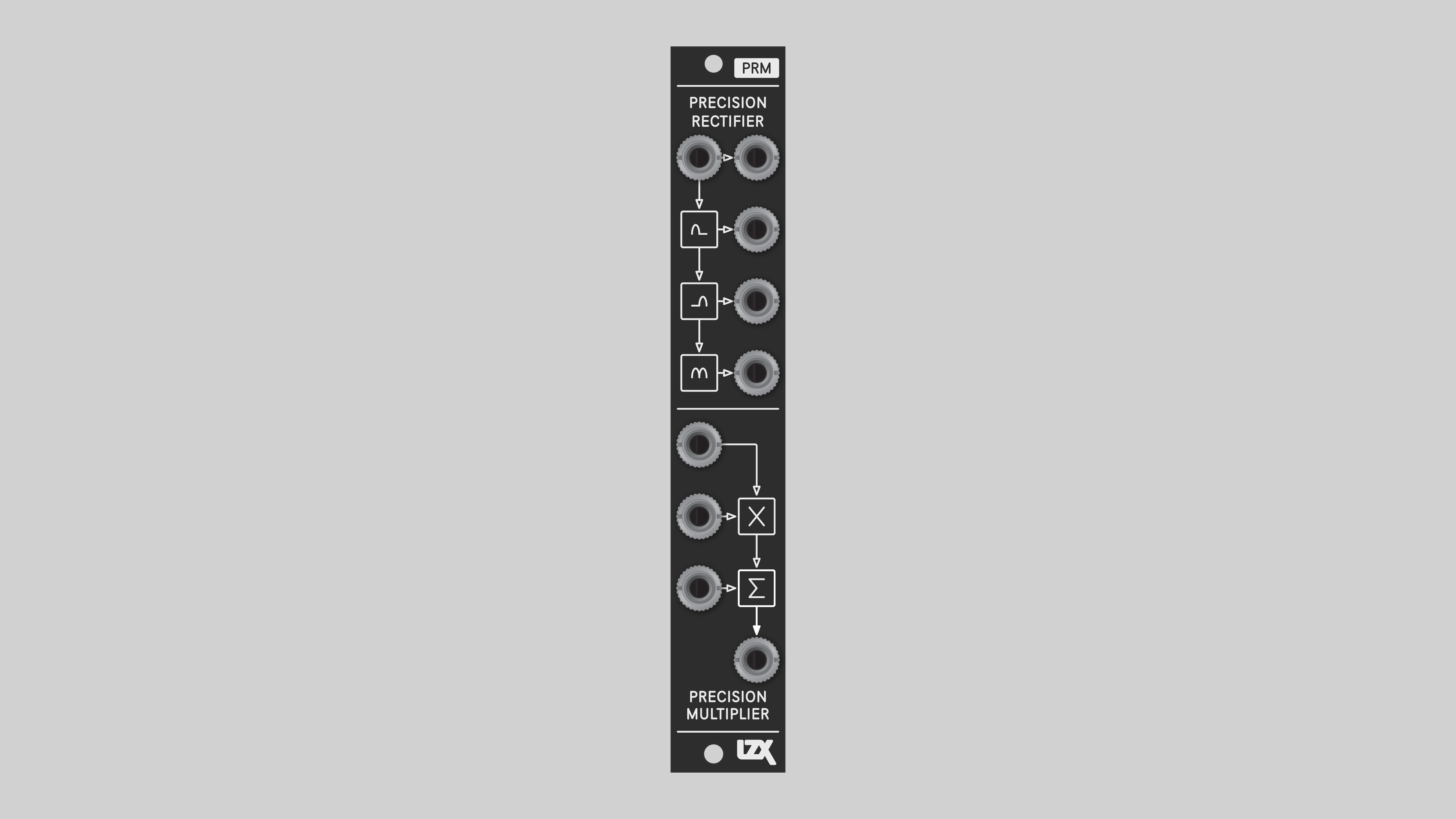
PRM is a multipurpose analog operator for modifying and combining signals. It's designed to cover as much functional territory as possible in a compact and intuitive 4HP package.
PRM performs many basic processing steps, including:
- Full- and half-wave rectifying
- Half-wave inversion
- Two- and four-quadrant multiplication
- Antisine/exponential waveshaping
In combination with PGO Programmable Gain and Offset, and/or PAB Programmable Active Buffers, PRM modules can also perform complex functions such as:
- One-quadrant multiplication
- Linear and parabolic frequency doubling
- Sine/logarithmic waveshaping
- Division
- Blending and logical operations such as:
- Minimum / AND
- Maximum / OR
- Difference / XOR
- Rotations
- Voltage limiting
Key Specifications
| Parameter | Value |
|---|---|
| Mounting Width | 4 HP |
| Power Consumption | 12V @ 75mA |
| Power Connectors | 10 pin EuroRack ribbon, 2.1mm DC barrel |
| Video Sync | None |
| Included | DC barrel power cable, EuroRack power cable, red panel, green panel, blue panel |
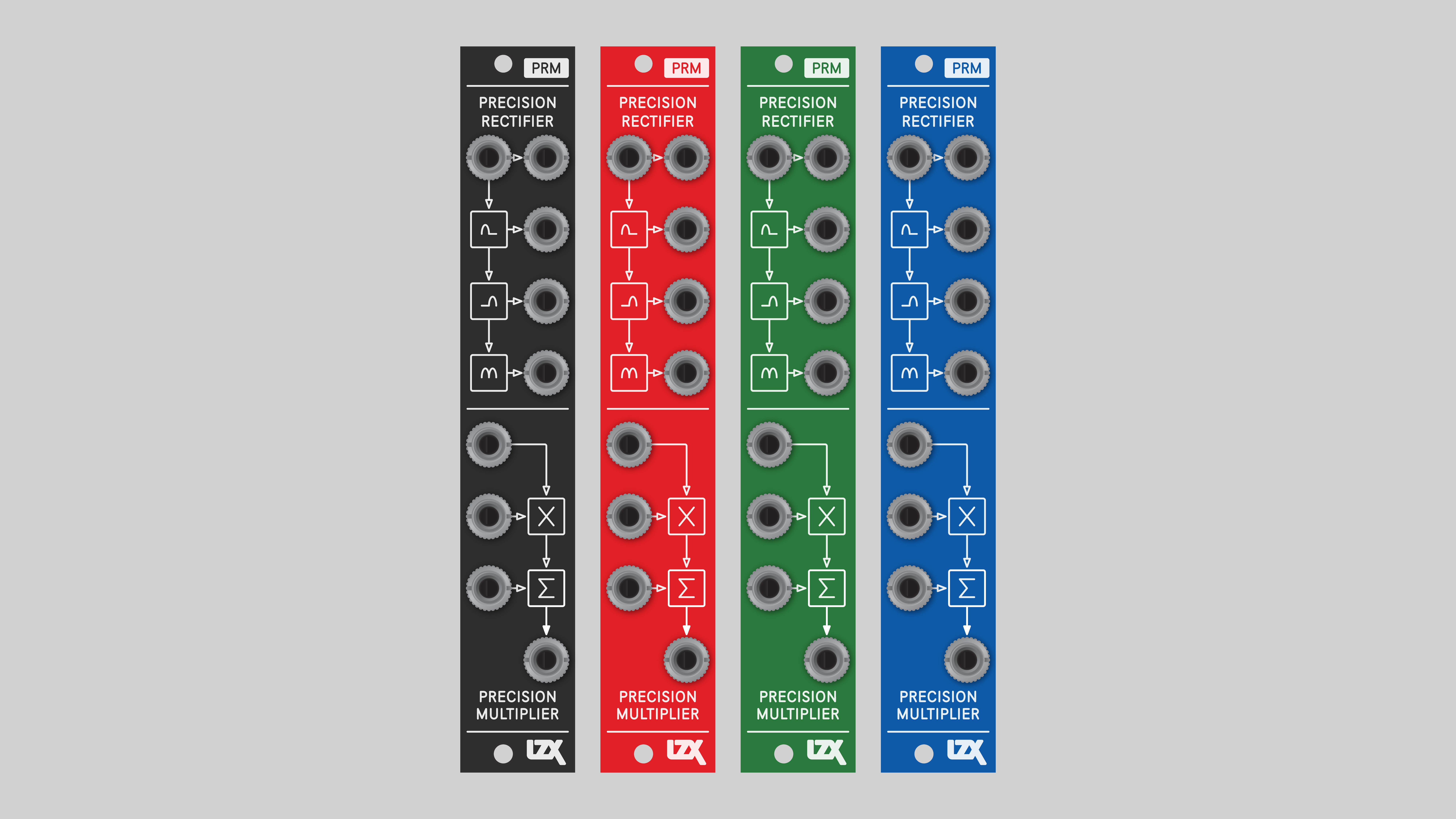
Front Panel Options
PRM ships with a black front panel installed. Red, green and blue panels are also included.
System Integration Advice
Utility module for wavefolding, multiplication, and summing, covering odd cases where the patch needs just one simple operation.
Expander module to add extra inputs or output processing. Extend the functionality any module. Add one next to your favorite oscillators or RGB functions to expand modulation or signal input options.
Building block for patching complex video synthesis functions. As low-level analog computing blocks, several P-series modules can be patched together to design a wide range of processing functions, including replicating functions from other modules. However, this level of flexibility comes at the expense of greater system size and more complex patches. Using both lower level and higher level modules is a great strategy for getting the most out of a system.
Consider multiple PRMs. Analog computers provide several instances of multiplier and summing operators.
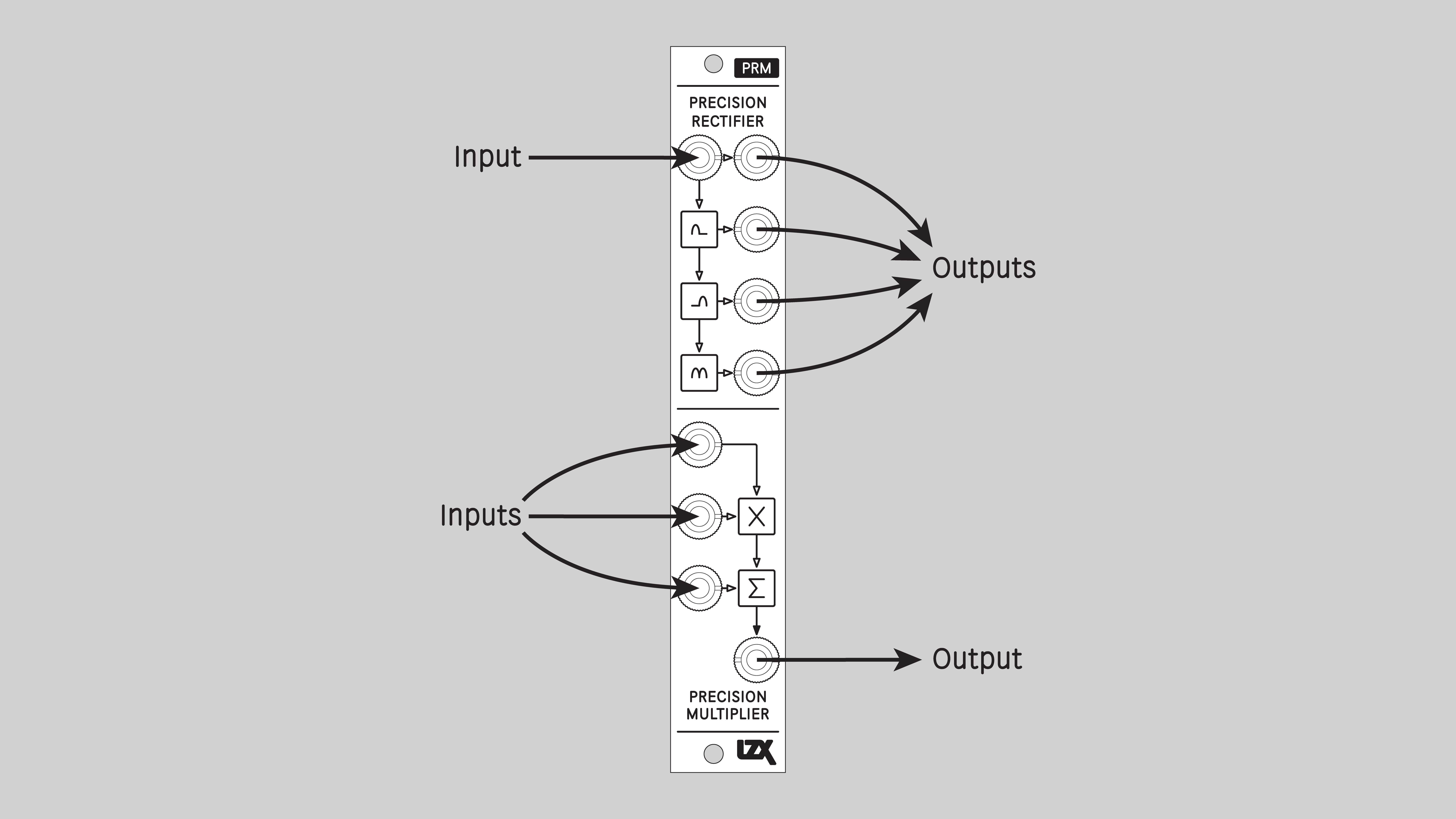
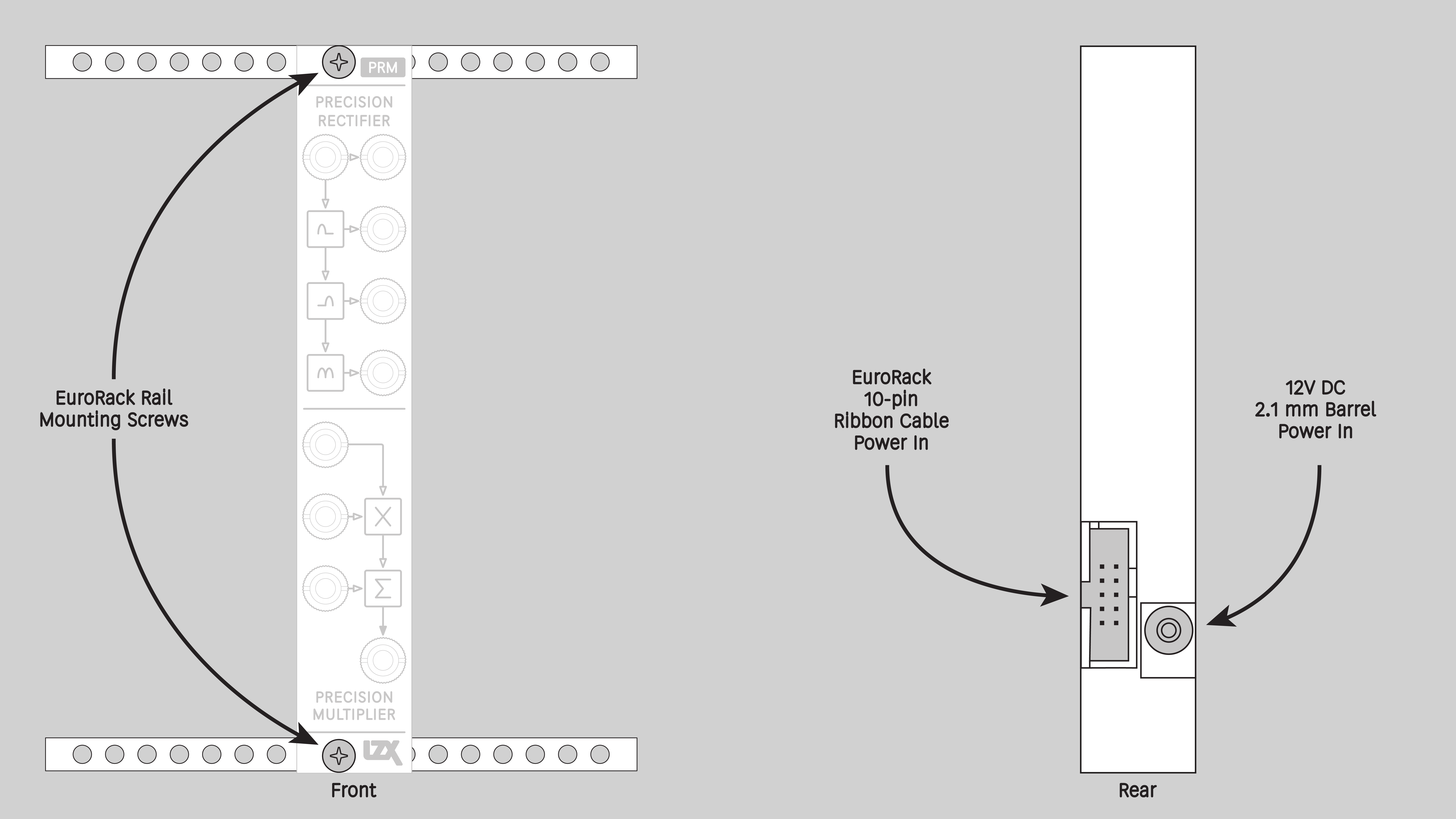
Connectors
The PRM design was informed by years of studying interfaces common to the building blocks of analog computers and video processing equipment.
Operation
P-series modules are precision instruments. DIY PRM modules must be calibrated before use. Assembled PRM modules are calibrated at LZX HQ, but may need adjustment from time to time. See the Calibration section below.
Example PRM Patches
Half-wave Rectify
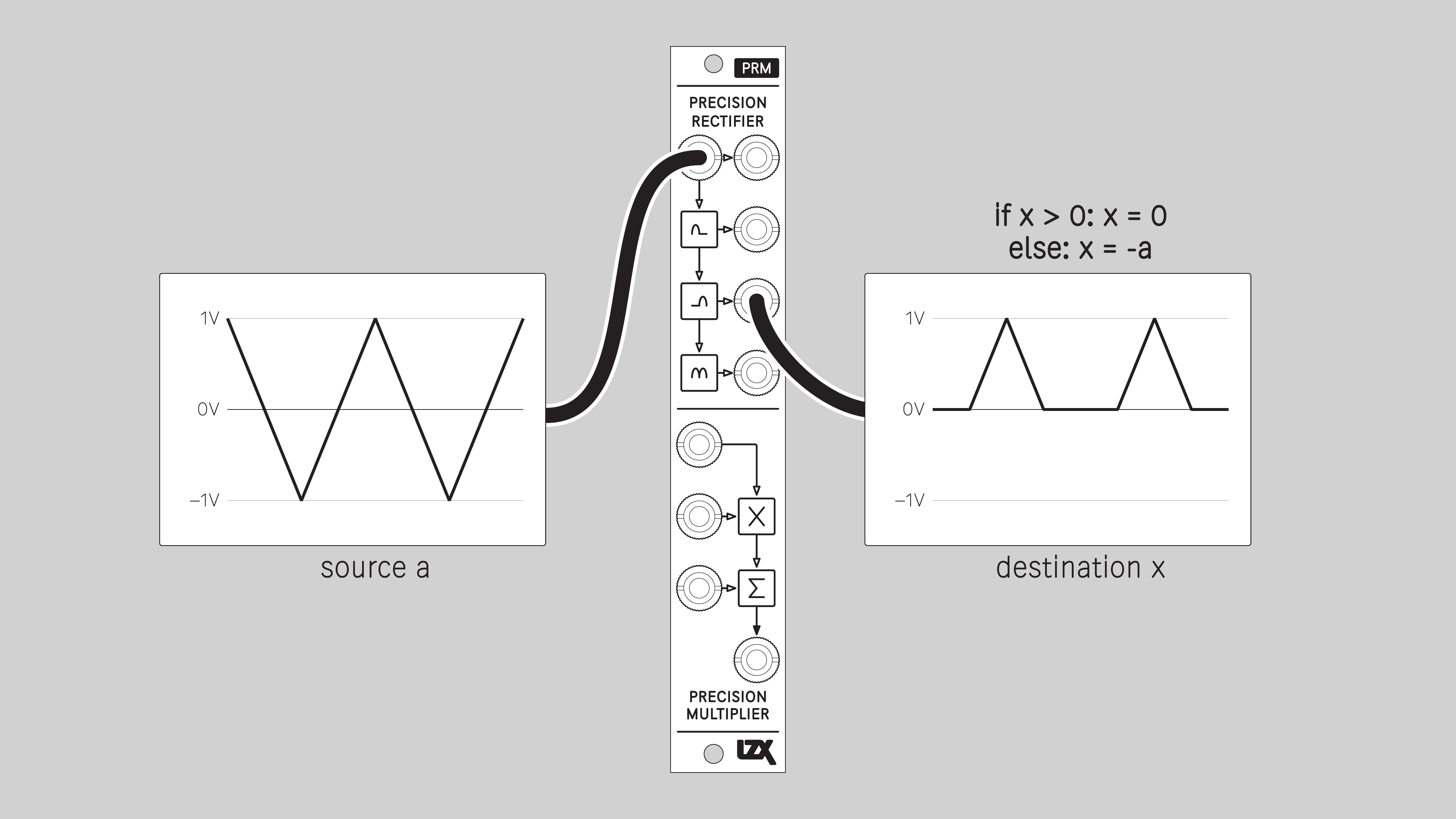
Half-wave Invert
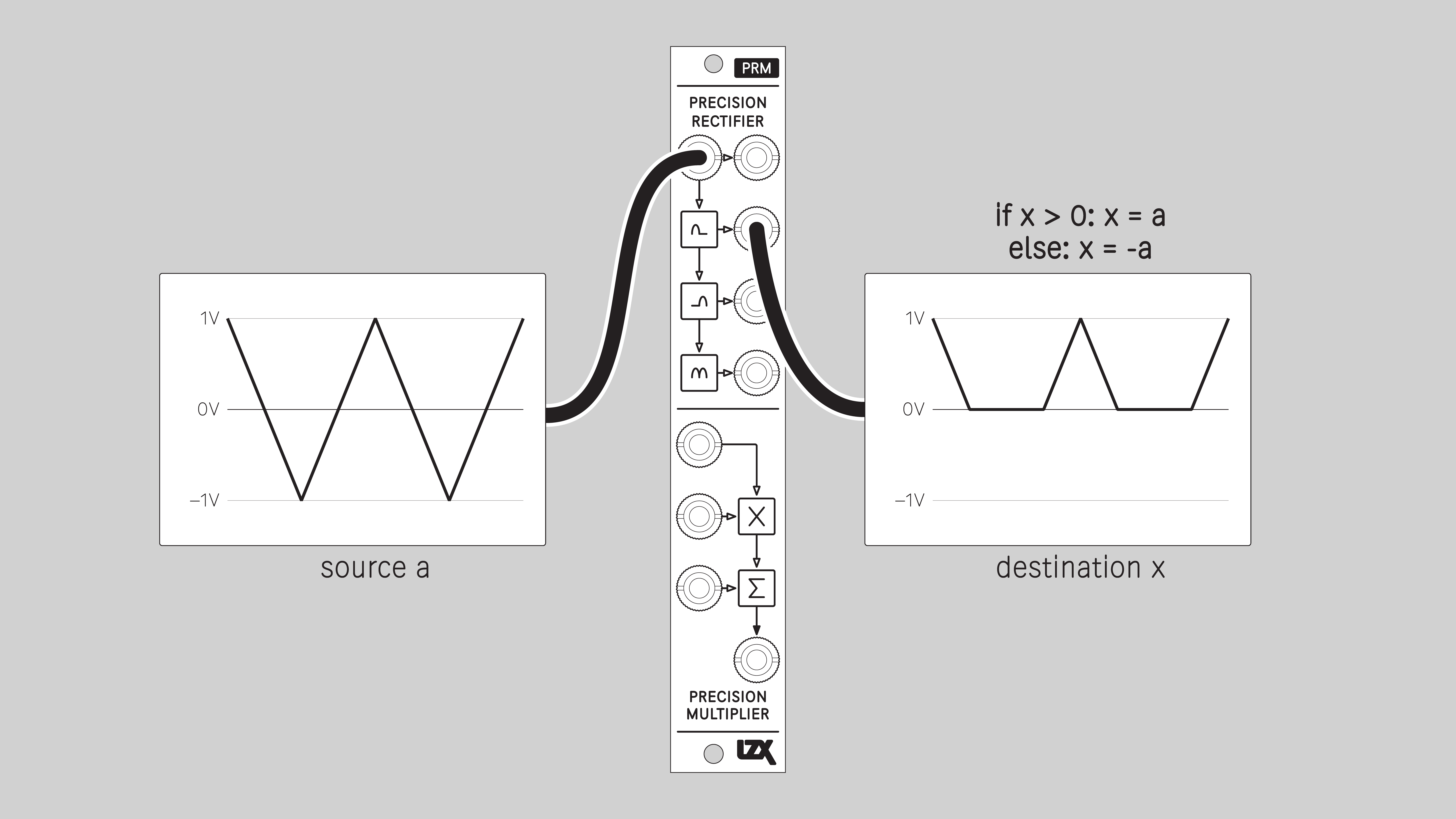
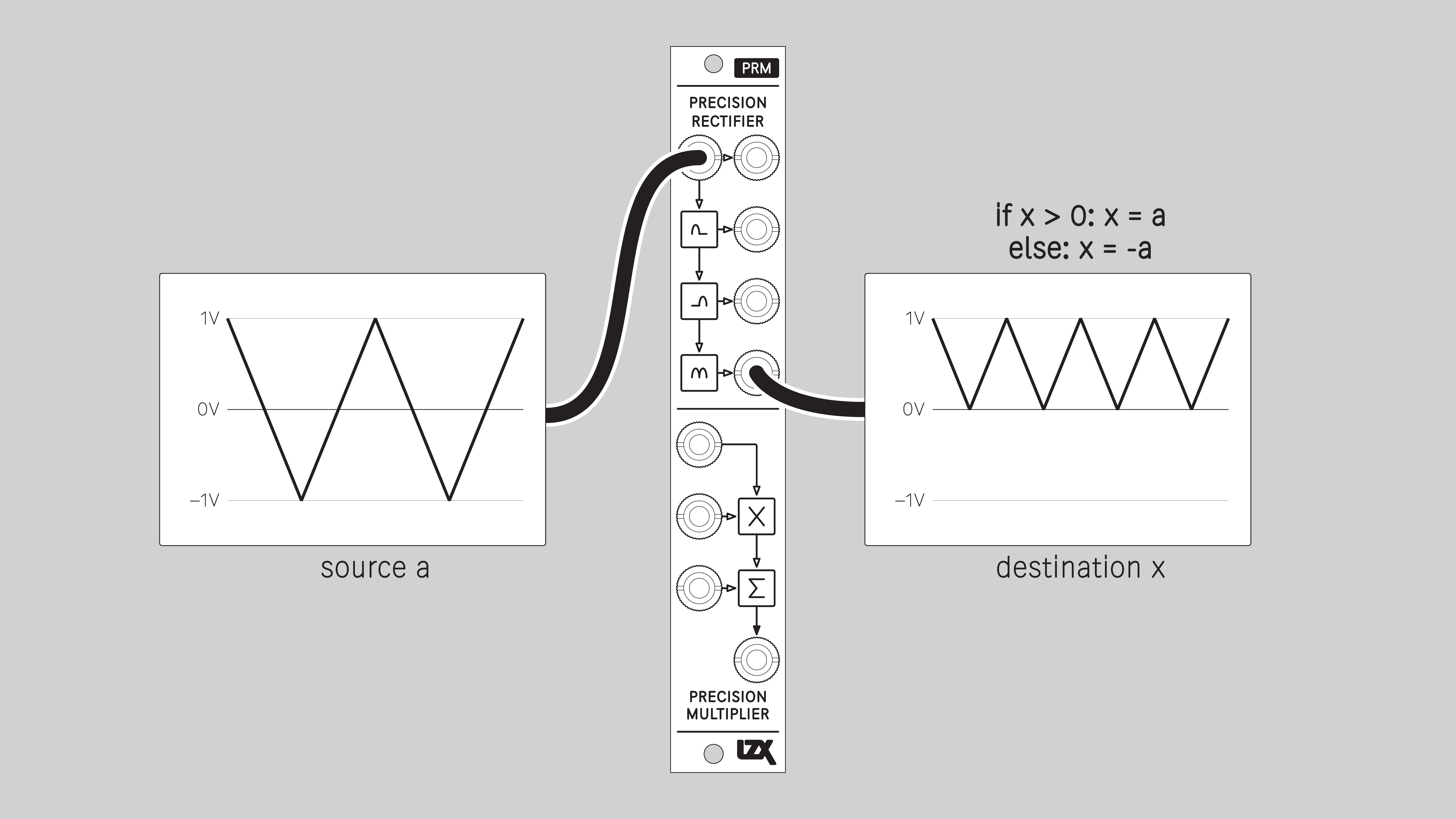
Full-wave Rectify
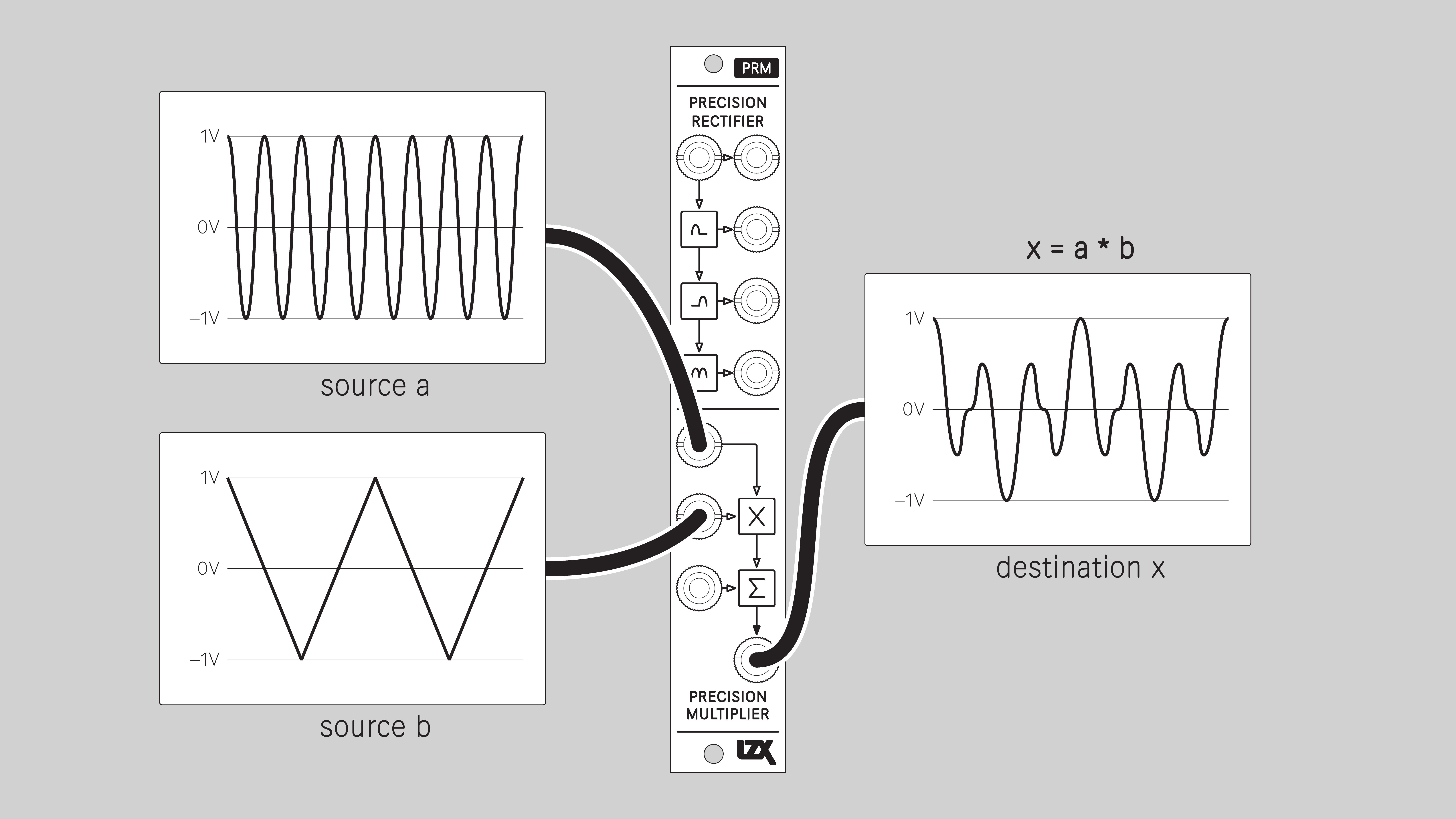
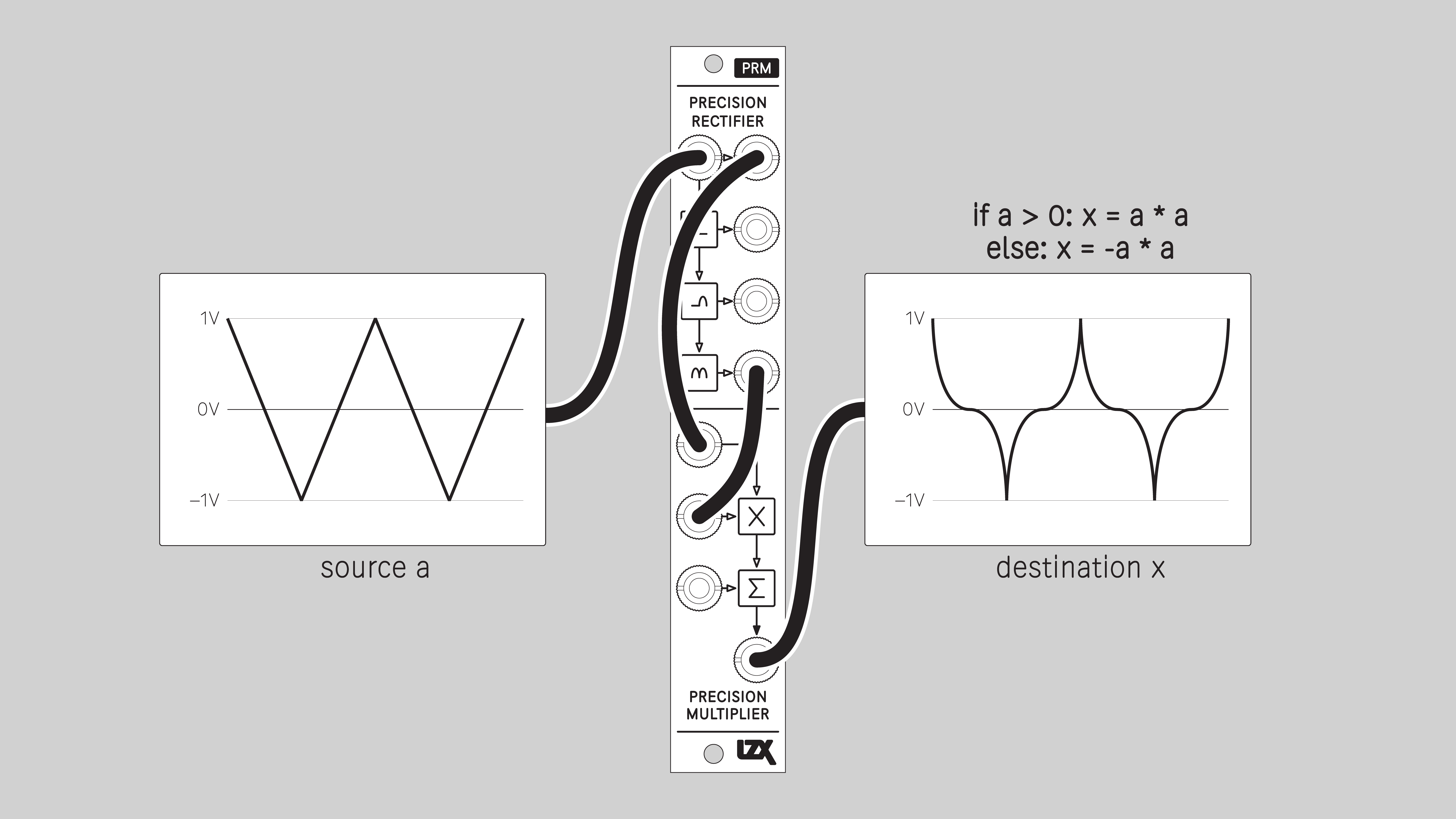
Four-quadrant Multiply
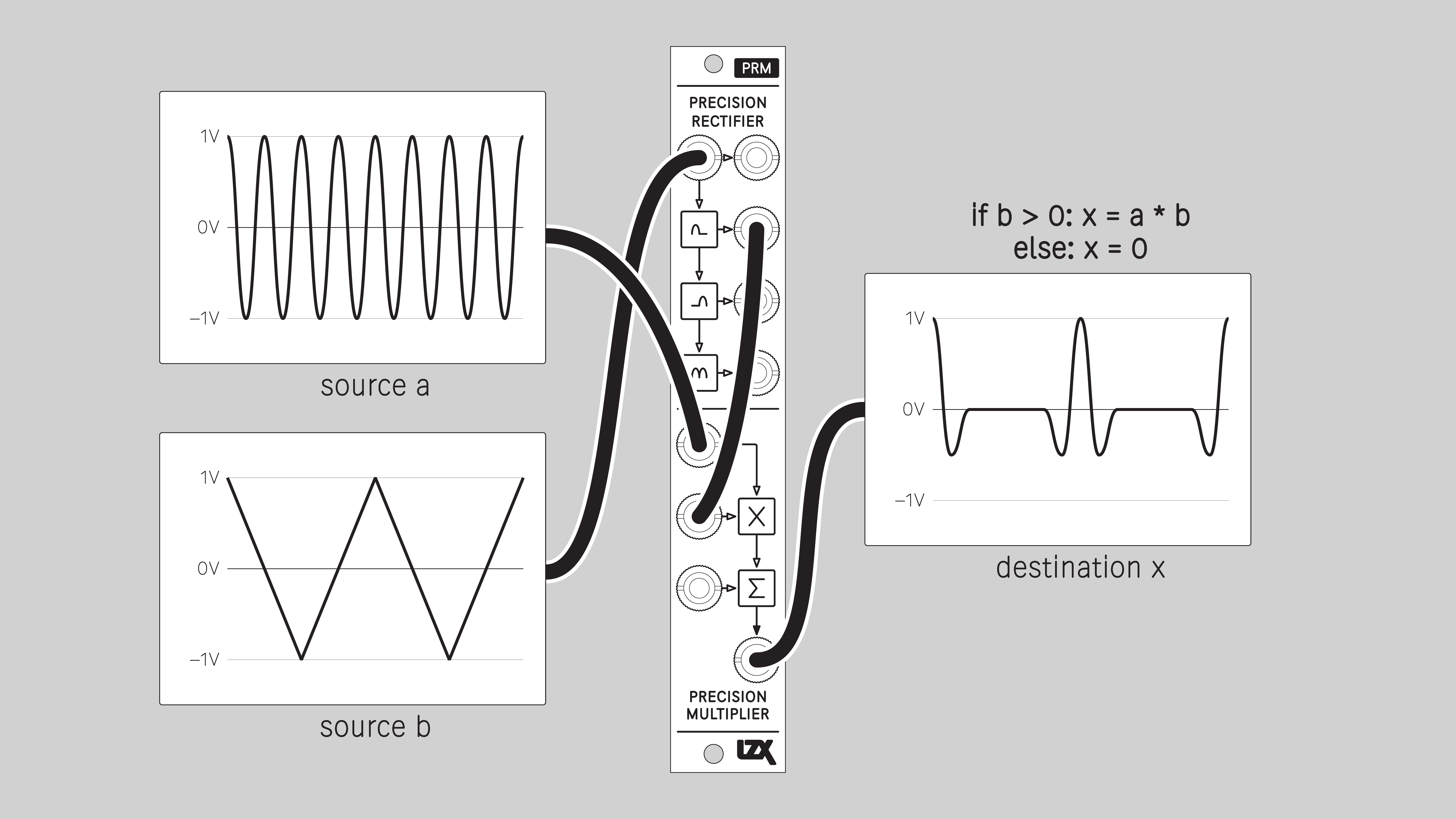
Two-quadrant Multiply
Exponential / Antisine
Example P-series Patches
One-quadrant Multiply
Sine
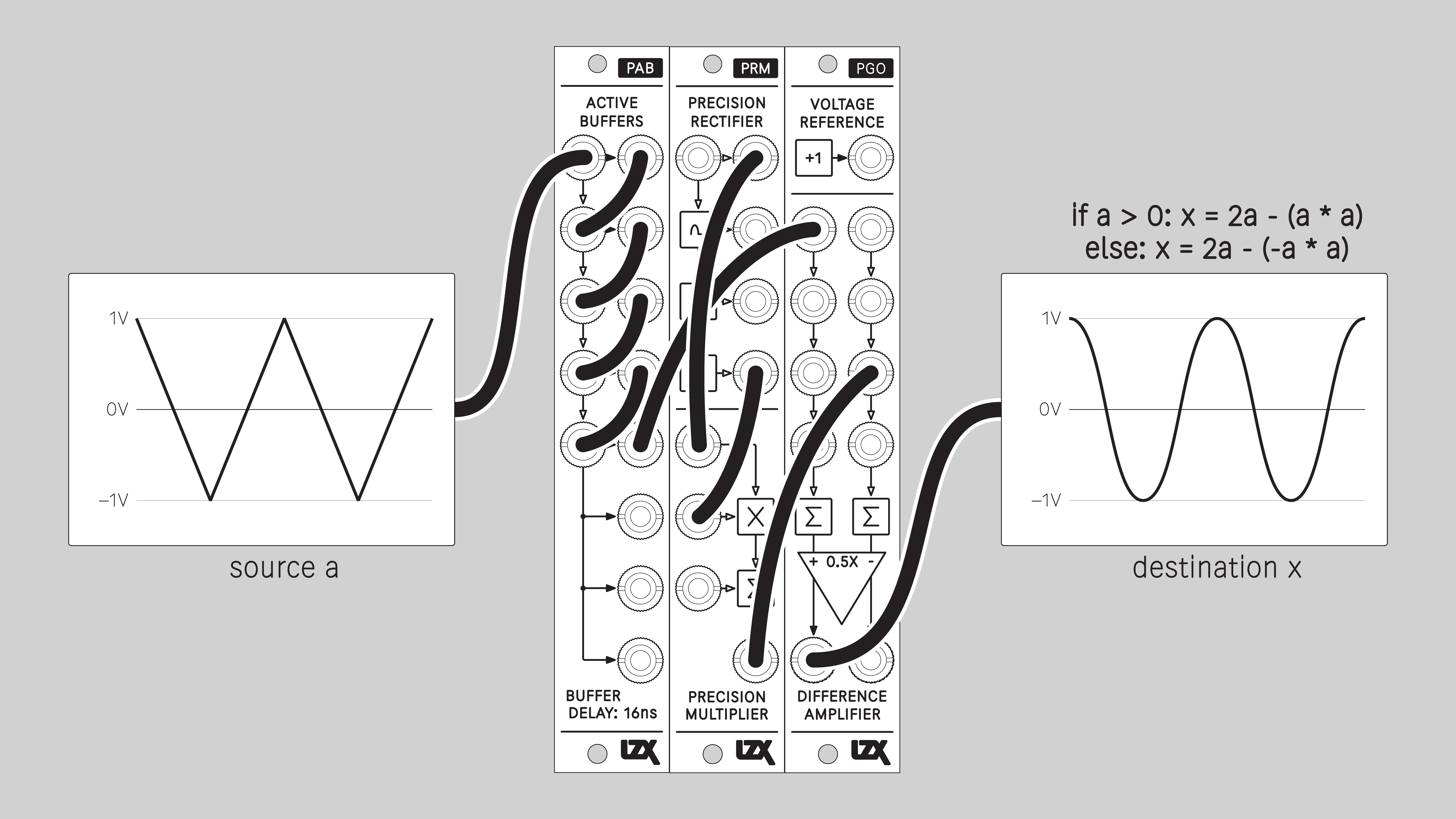
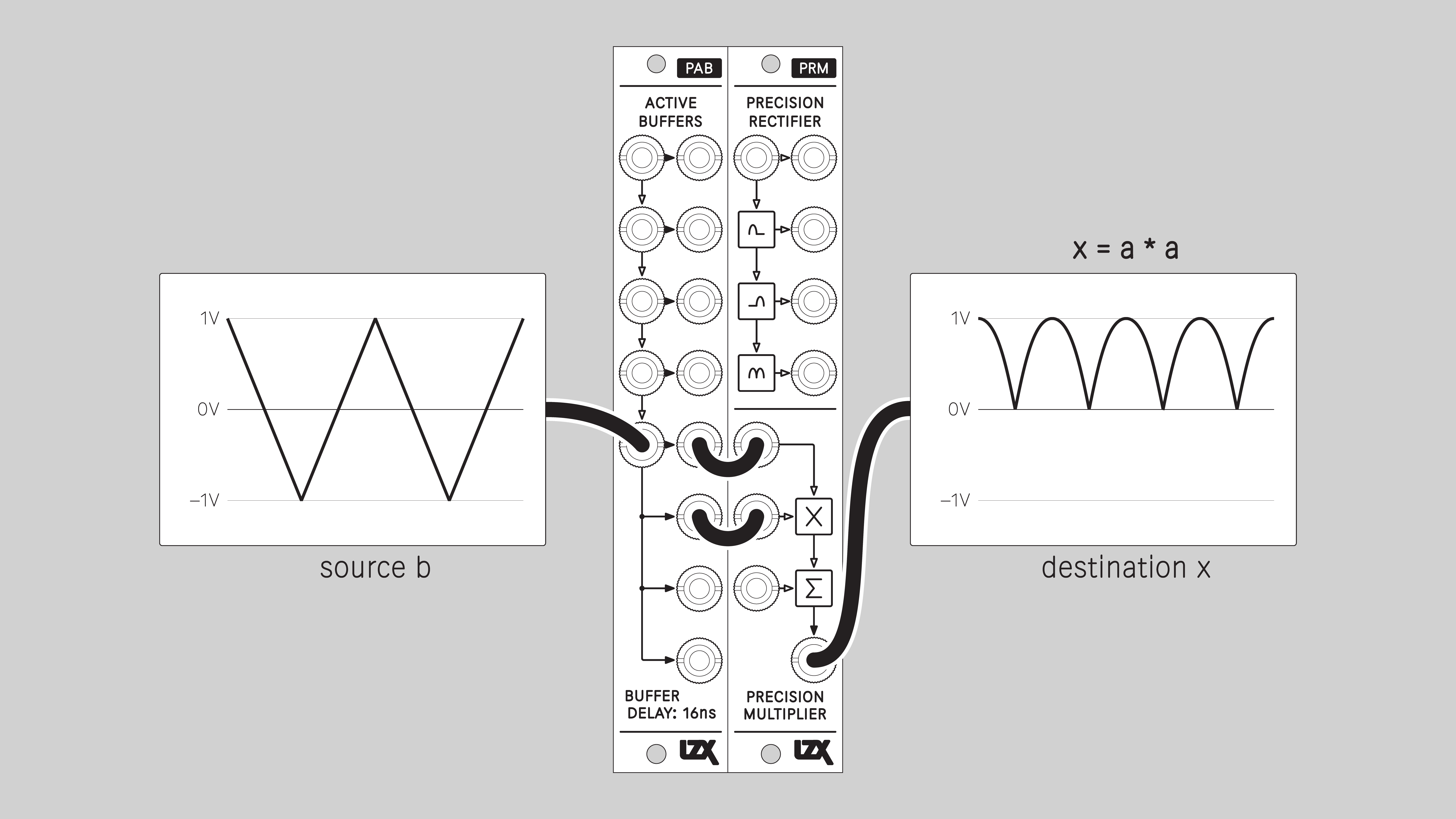
Double Frequency / Parabolic
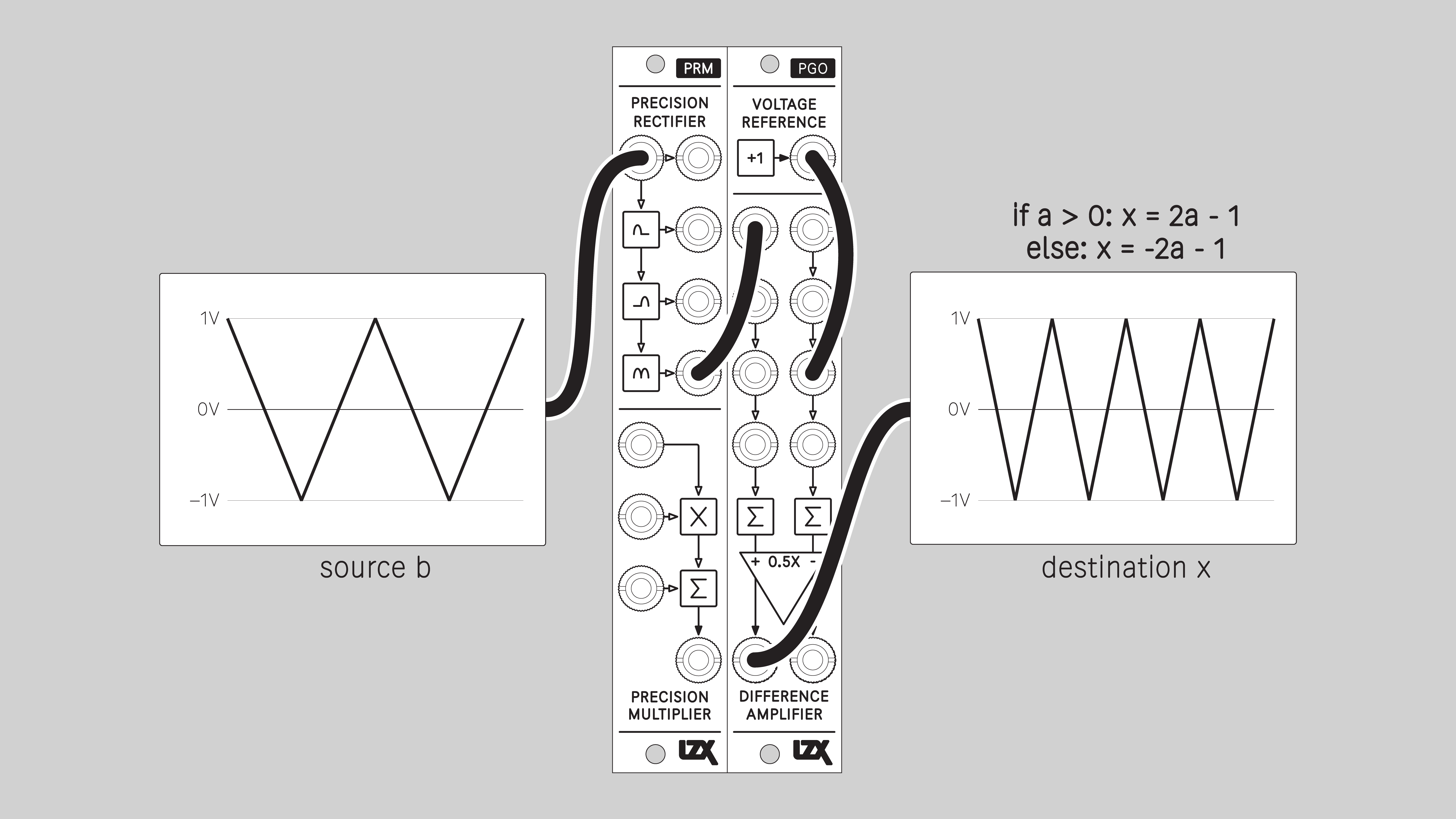
Double Frequency / Ramp to Triangle
Similar to full-wave rectify, but scales the output to match the bipolar range of the input.
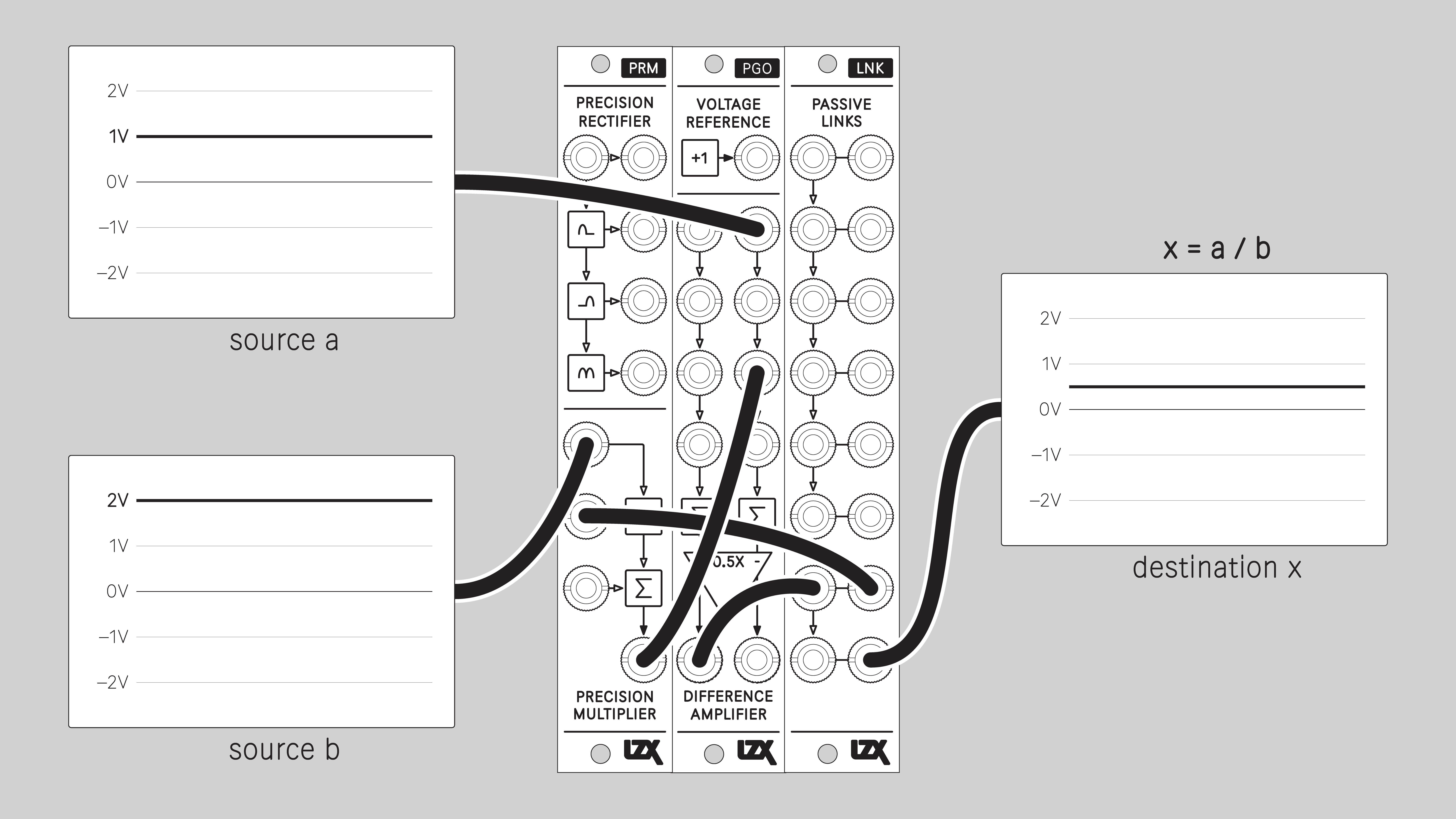
Divide
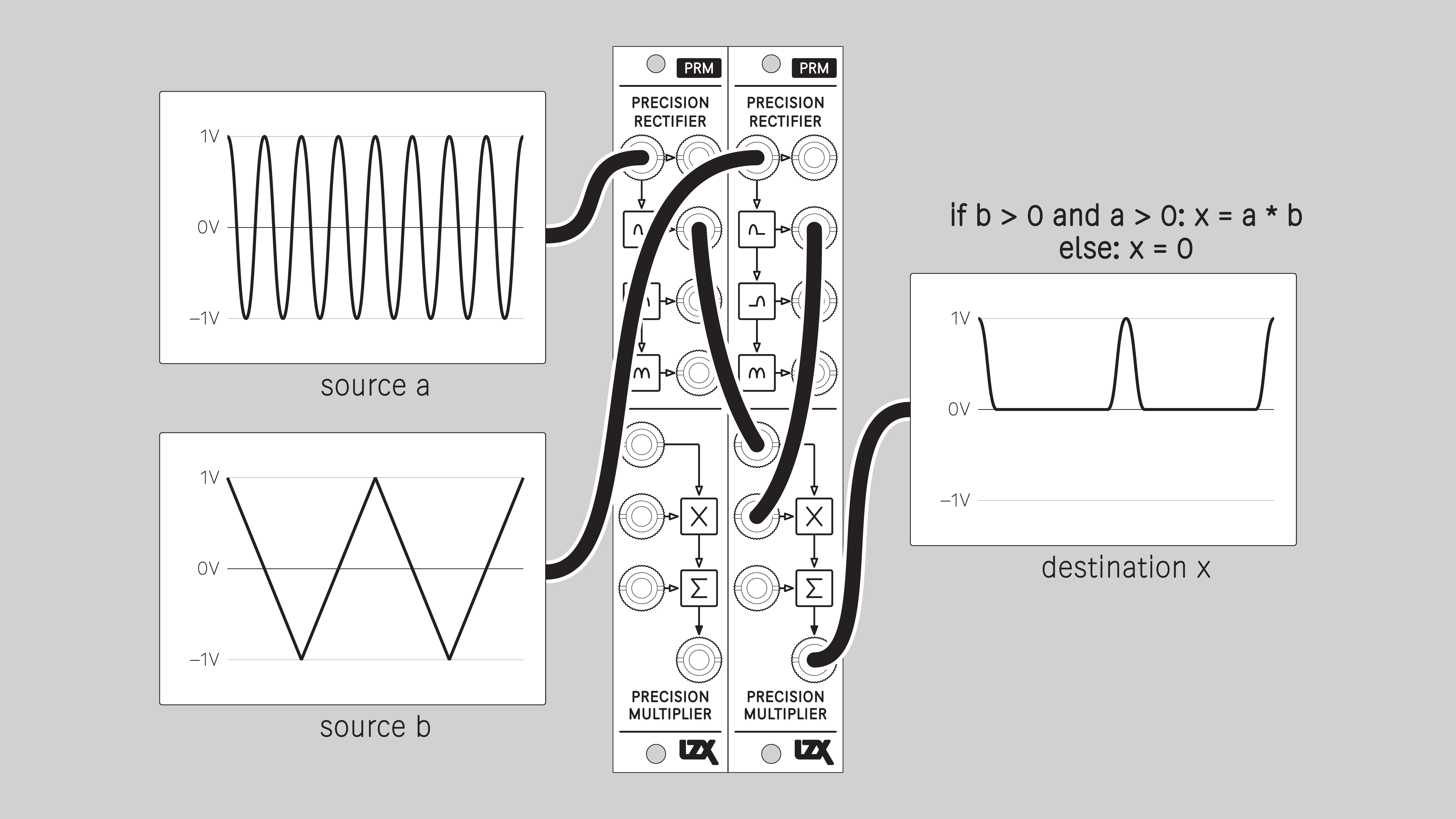
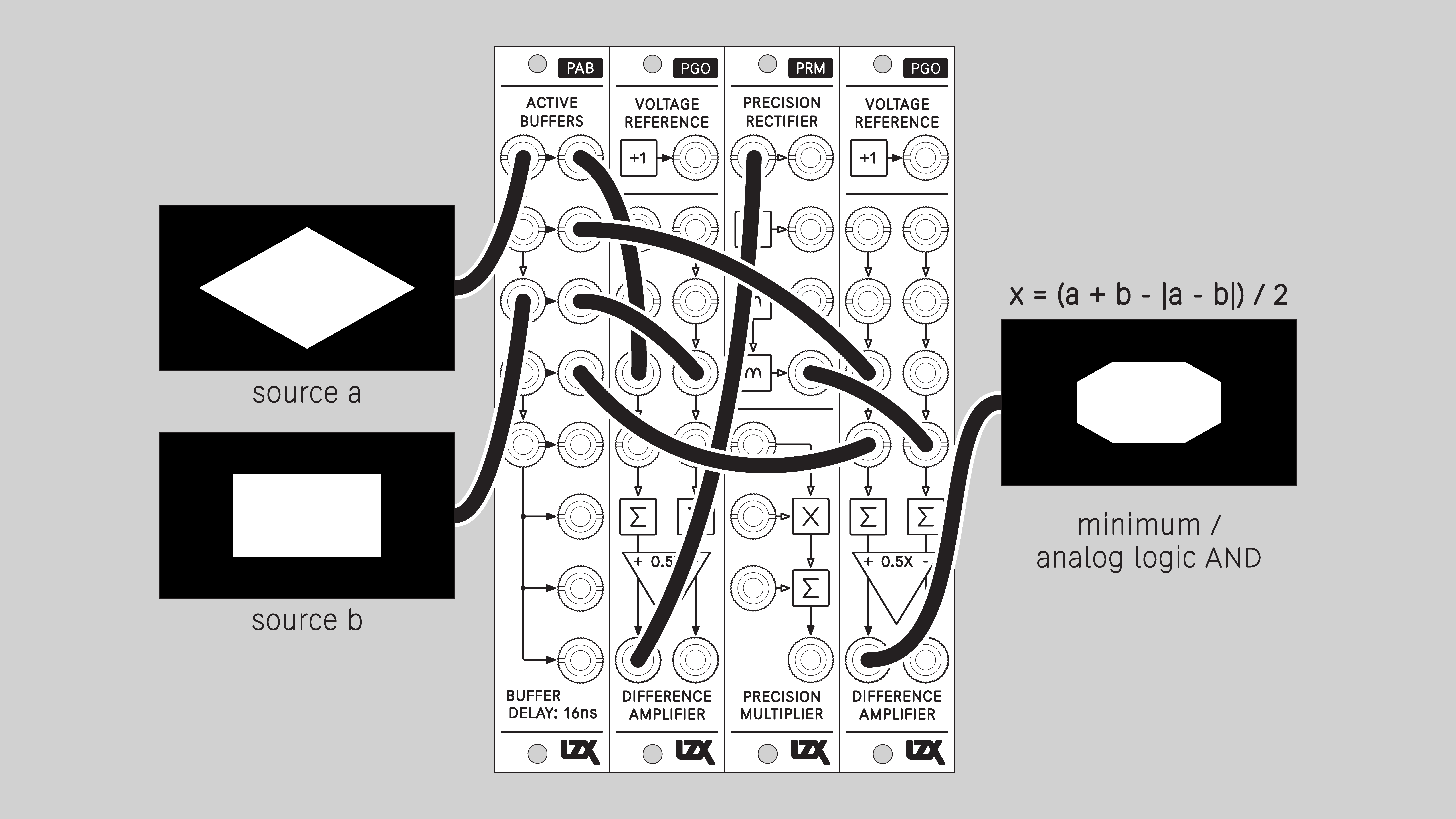
Minimum / Logical AND
The lower of two input values. Corresponds to a logical AND operation.
An output value can only be high if A and B inputs are high.
Blend mode: Minimum
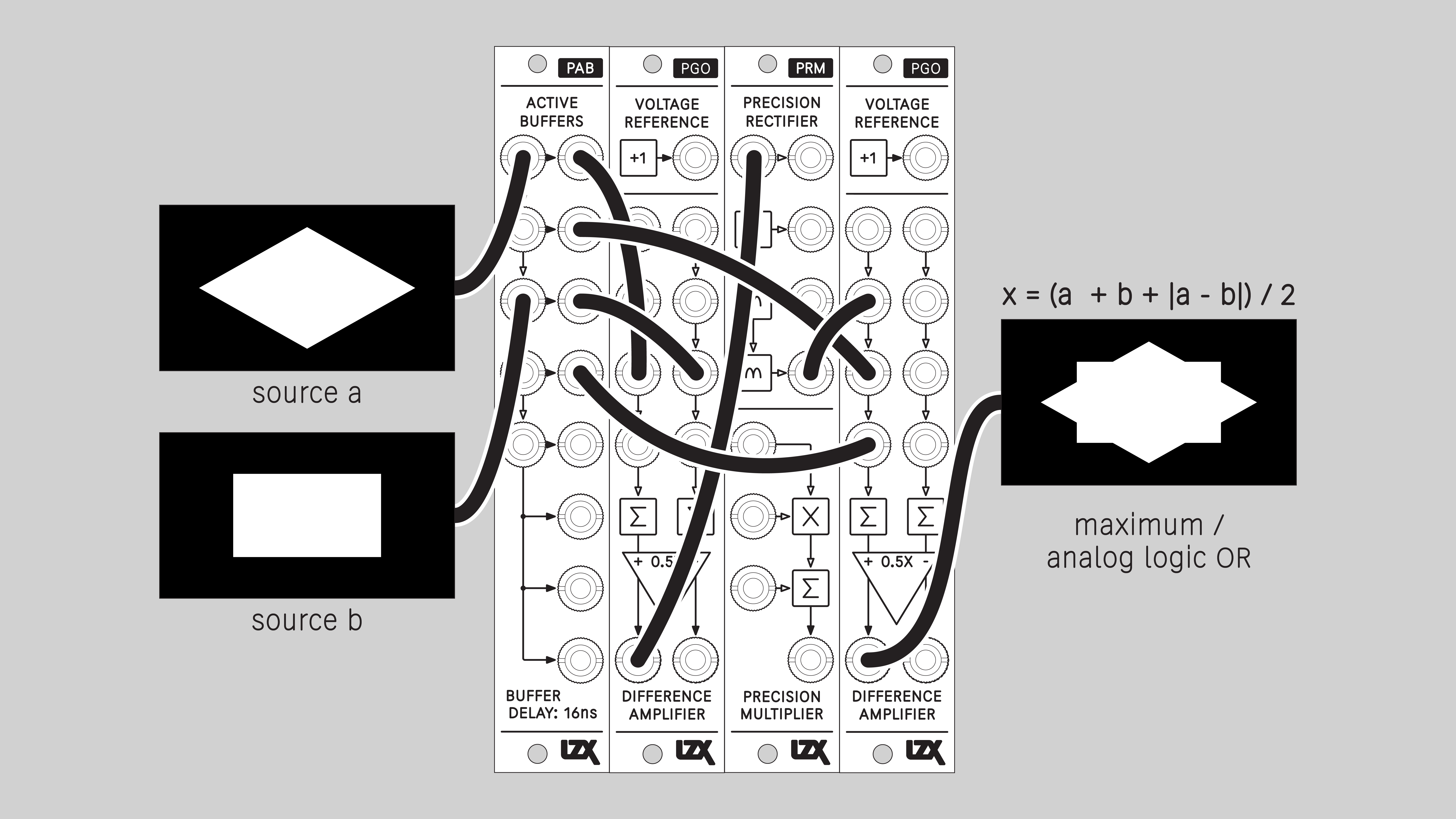
Maximum / Logical OR
The higher of two input values. Corresponds to a logical OR operation.
An output value will be high if either A or B inputs is high.
Blend mode: Maximum
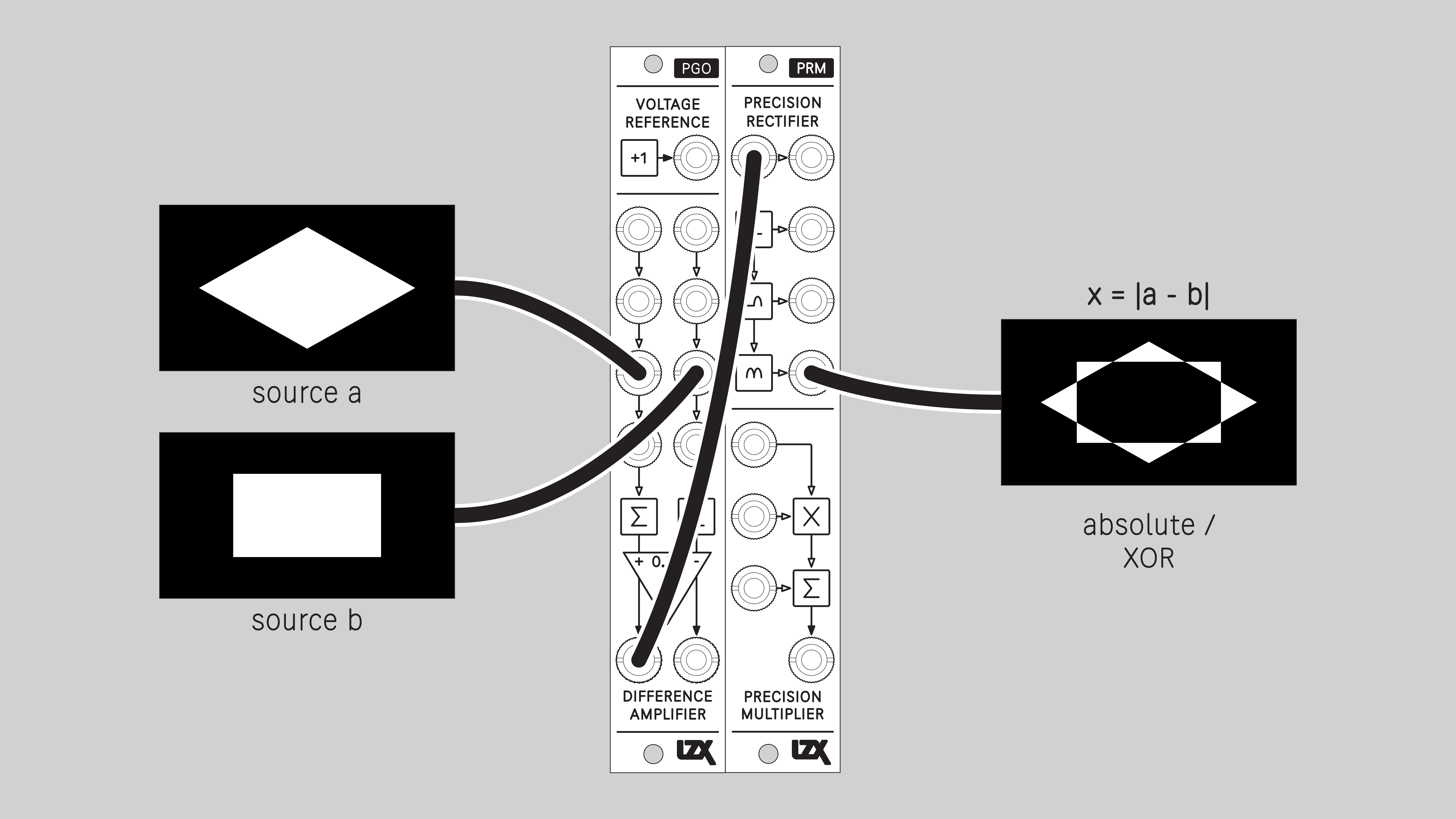
Difference / Logical XOR
The absolute value of the difference between two input values. Corresponds to a logical XOR operation.
An output value will be high if the difference between A and B inputs is large. An output value will be low if the difference is small.
Blend mode: Difference
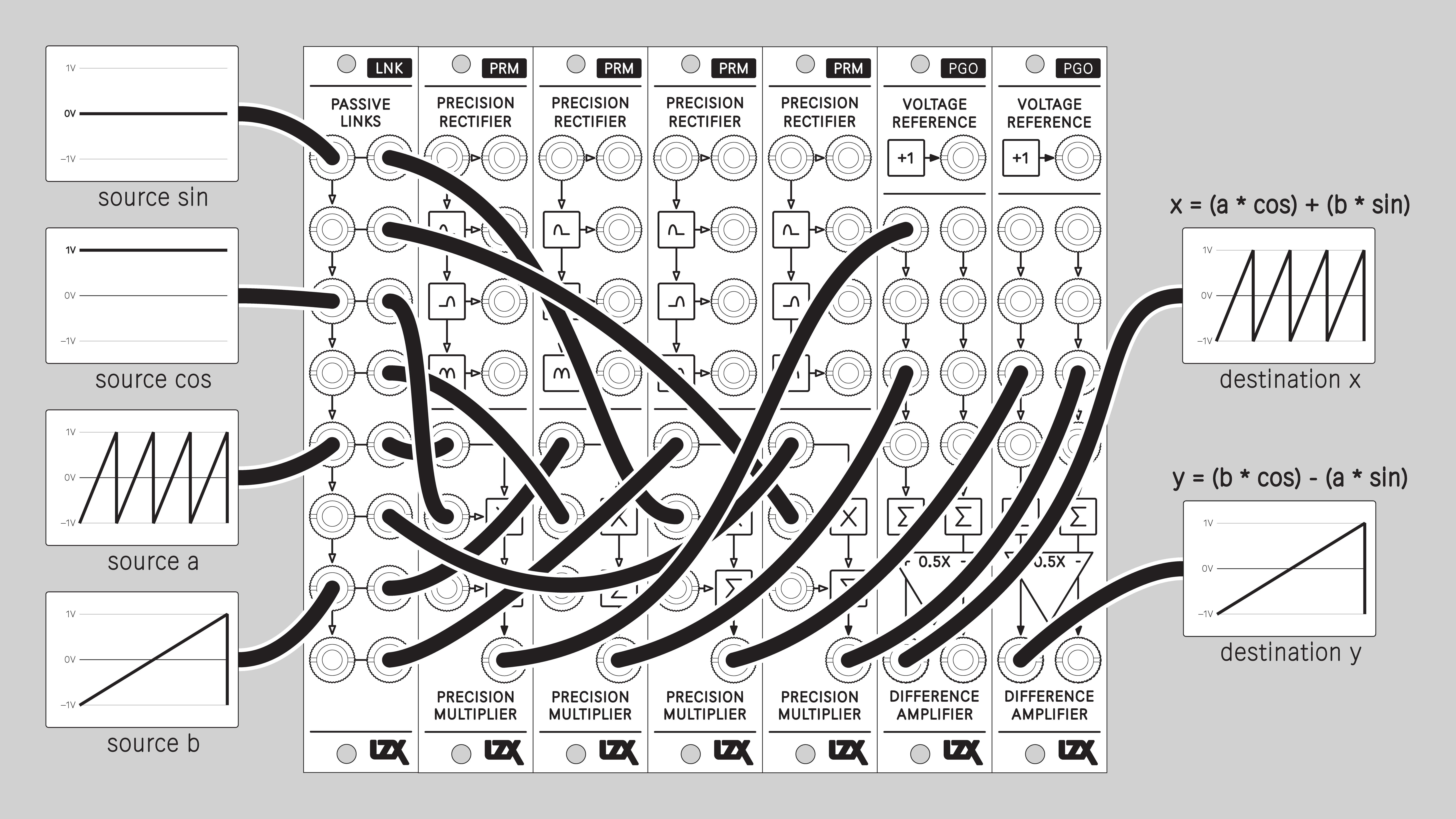
2D Rotation
Rotate a figure that is defined by horizontal and vertical input signals. Typically, this means horizontal and vertical ramps. Sending the outputs of this patch to a vector display or XYZ oscilloscope allows rotation of the video raster.
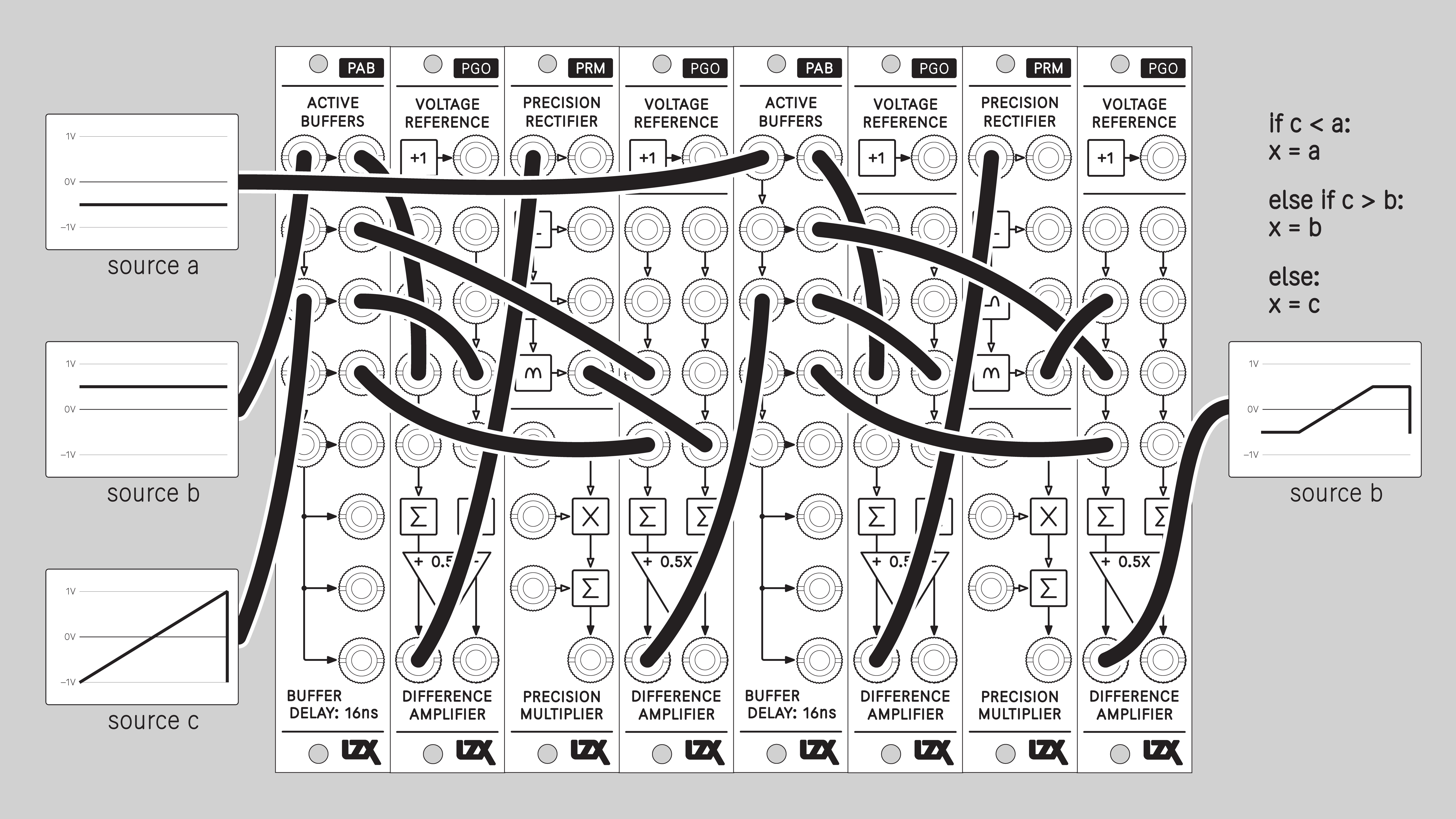
Limit Voltage
Installation
Requirements
- EuroRack enclosure
- 12V DC or EuroRack power supply
- 2.1 mm DC barrel power cable or EuroRack power cable (both options included)
- Eurorack power for PRM requires a 16-pin to 10-pin ribbon cable
- Two M2.5 x 6mm mounting screws, or screws provided or specified by the enclosure manufacturer
- #1 Phillips head screwdriver, or hand tool provided or specified by the enclosure manufacturer
Procedure
- Power off and disconnect the EuroRack enclosure's power supply and any attached DC adapters.
- Connect either the EuroRack Power Cable or the DC Barrel Power Cable to the module. Do not connect both Eurorack and DC Barrel power.
- Ensure that no mounting screws are in any holes in the area where you wish to mount the module.
- Carefully test fit the module with its attached power cable in the open space in the EuroRack enclosure. If it is obstructed by the enclosure or any internal assemblies, abort this procedure.
- Connect the disconnected end of the power cable to the power supply.
- Mount the module to the EuroRack rails using all mounting holes.
- Store the unused cable along with the product box in a safe location.
- Power on the EuroRack enclosure and start patching.
Full Specifications
| Parameter | Value |
|---|---|
| Manufacturer Part Number | 950066 |
| Pronunciation | piː-rɒm |
| Mounting Width | 4 HP |
| Mounting Hole Count | 2 |
| Power Consumption | 12V @ 75 mA |
| Power Connectors | 10 pin EuroRack ribbon, 2.1mm DC barrel |
| Input Impedance | 1M ohms |
| Output Impedance | 75 ohms |
| Input Protection Range | +/-20V |
| Input Clipping Range | +/-2.5V |
| Output Range | +/-2.5V |
| Propagation Delay | 32ns |
| Module Width | 20.32 mm |
| Module Height | 128.5 mm |
| Product Box Width | 4 in / 101.6 mm |
| Product Box Height | 2 in / 50.8 mm |
| Product Box Depth | 6 in / 152.4 mm |
| Included | DC barrel power cable, EuroRack power cable, red panel, green panel, blue panel |
| EuroRack Power Cable Type | 10-pin to 16-pin |
| EuroRack Power Cable Length | 25 cm |
| DC Barrel Power Cable Length | 25 cm |
| RoHS Compliance | Manufactured with lead-free processes. |
| Video Sync | None |
Calibration
Calibration requirements
- Power source
- Bipolar +/- 1v triangle oscillator @ ~1 kHz
- Bipolar +/- 1v square oscillator @ ~10 kHz
- Oscilloscope
- Adapter cable: male mini plug to male BNC plug
- Micro-trim adjustment tool or jeweler's screwdriver
- Magnifying lens (if needed)
Calibration procedure
- Power down the system and unmount the module if needed.
- Connect power to module.
- Power up the system.
- Set oscilloscope horizontal and vertical ranges to visualize the waveform between +/- 1v.
- Set oscilloscope sweep activation threshold to approximately 0.5v. It may be necessary to adjust the threshold throughout the calibration process.
Patching the bipolar test oscillators
If using a modular system to supply the test oscillators, follow these steps:
- Set DWO3 Oscillator 1 Frequency Range to Free Lower Vertical.
- Set DWO3 Oscillator 1 Frequency knob to three o'clock, and Freq CV Depth knob centered. This gives a frequency of approximately 1 kHz.
- Patch DWO3 Oscillator 1 Triangle output to SMX3 input A2.
- Patch 1v static voltage to SMX3 input C1.
- Patch SMX3 output 2 to oscilloscope.
- Adjust SMX3 A2 and C2 knobs to tune the oscillator gain and bias to precisely +/- 1v.
- Set DWO3 Oscillator 2 Frequency Range to Free Upper Vertical.
- Set DWO3 Oscillator 2 Frequency knob to nine o'clock, and Freq CV Depth knob centered. This gives a frequency of approximately 10 kHz.
- Patch DWO3 Oscillator 2 Square output to SMX3 input A3.
- Patch SMX3 output 3 to oscilloscope.
- Adjust SMX3 A3 and C3 knobs to tune the oscillator gain and bias to precisely +/- 1v.
Rectifier submodule calibration
- Patch the +/- 1v triangle wave to the Rectifier input
- Patch the bottom Rectifier output to the oscilloscope
- On the rear of the module, adjust the top trim pot until the folded waveform is uniform, with all peaks at 1v.
Multiplier submodule calibration
- Patch the +/- 1v triangle wave to the first, top Multipler input.
- Patch the +/- 1v square wave to the second, middle Multiplier input.
- On the rear of the module, adjust the middle Amplitude pot and the bottom Bias pot until the multiplied waveform is uniform, ranging from -1v to +1v.
Maintenance
Keep your module free of dust and debris by performing periodic cleaning. Spots may be cleaned from the frontpanel with a microfiber cloth and isopropyl alcohol or other electronics cleaner.
Hardware Revisions
The hardware revision code is printed on the circuit board visible from the rear of the module.
PRM-RevA
Initial prototype. September 2024.
PRM-RevB
Second prototype. December 2024.
PRM-RevC
Third prototype. January 2025.
PRM-RevD
Initial production version. February 2025.
PRM-RevD Schematic Diagram
Download PDF
PRM-RevD Interactive Bill of Materials
Download ZIP
DIY
PRM is available as an assembled module, a full DIY kit, or a partial DIY kit.
Downloads for the complete schematic and an interactive HTML Bill of Materials are found in the Hardware Revisions section above.
Partial DIY Components
The partial DIY kit from LZX includes the printed circuit board and front panel. The following components must be purchased separately from electronics parts vendors.
| Manufacturer | Manufacturer Part Number | Description | Quantity | Reference Designators |
|---|---|---|---|---|
| Wenzhou QingPu Electronics Co., Ltd | WQP-WQP518MA | 3.5mm Jack Mono Switched | 9 | J4, J5, J6, J7, J8, J9, J10, J11, J12 |
| Pin Header Pitch 0.1in 2X5 Male Shrouded | 1 | J2 | ||
| Wurth Elektronik | 694106402002 | DC Jack Vertical 2.1mm Barrel | 1 | J3 |
| Recom Technologies | R-78K5.0-0.5 | DC/DC Converter Submodule 5.0V | 1 | U5 |
Assembly Instructions
This assembly job is recommended for intermediate level DIYers who are comfortable soldering thru hole joints in close proximity to surface mounted parts.
- Mount and solder rear-facing through hole parts first, in this order: pin header, DC/DC converter, DC barrel jack.
- Mount and solder front-facing jacks.
- Attach the front panel and secure it with mounting nuts for the jacks.
- Calibrate the module according to the Calibration procedure above.