ESG3
Overview
Critical to the video mission, ESG3 combines three essential functions into a compact form factor. ESG3 generates sync, outputs SD or HD video, and manipulates color. More than a utility module, ESG3 features integrated processing amplifiers, making it a creative instrument.
To output legal video signals from a modular synthesizer, an encoder is required. ESG3 converts LZX-compatible 1 volt signals to composite, RGB component, or YPbPr component video. It supports a wide range of video standards, from NTSC and PAL up to full high definition.
A modular synthesizer also requires a source of video sync. ESG3 generates sync with or without an external reference. It can be the ultimate source of sync, or genlock to incoming sync or video. Either way, ESG3 ensures that the entire modular system dances to the beat of the same drummer.
Proc amp controls allow aesthetic image manipulation. Each RGB channel features brightness and contrast adjustments. Invert or mute each channel with the flick of a switch. Invert or mute all outputs with another switch, making it easy to cut to black.
Legacy
ESG3 is the third-generation LZX module to feature sync generation, encoding, and color correction. In the Visionary series, those functions were provided by two separate modules, the Color Video Encoder and the Video Sync Generator. Visual Cortex was the Expedition series all-in-one solution for those functions, and many more. It had a different set of tools for colorization.
ESG3 combines the functions of the Visionary encoder and sync generator modules. It follows a more familiar color correction scheme, with brightness and contrast controls per RGB channel. ESG3 also adds switches to invert or mute individual channels, or the entire mix. It doesn't include S-video output, but supports all standard HD formats.
Key Specifications
| Mounting Width | 12 HP |
| Power Consumption | 12V @ 300mA |
| Power Connectors | 16 pin EuroRack ribbon, 2.1mm DC barrel |
| Included | DC barrel power cable, EuroRack power cable, RCA sync cable |
| Video Sync | Rear RCA in & out |
System Integration Advice
Any modular video synthesizer needs at least one encoder and exactly one sync generator. Encoders are the only way to get legal video out of the system. The sync generator is required by any module that needs to genlock to video sync. Ramp generators and video-synced oscillators are the most obvious examples. Many other Gen3 modules require sync. For example, all toggle switches, such as those on FKG3, refer to video sync to ensure that the switching happens in the vertical interval between frames, preventing frame tearing or glitching.
Especially in smaller, portable systems, the value of the ESG3 proc amp controls becomes more evident. The inclusion of contrast and brightness controls on ESG3 reduces the need for other processing modules and simplifies many patches. This in turn can improve visual quality in high definition formats by shortening the signal chain.
Larger systems may benefit from multiple encoders. In complex patches, it may be desirable to output more than one video signal, perhaps to be composited by an external mixer. Each output from the system requires an encoder. ESG3 is not the only option; Chromagnon has an onboard encoder, with a different feature set.
ESG3 can serve as the source of sync for the entire system, or indeed for an entire studio. Or ESG3 can receive sync from an external source via the sync input on the rear of the module.
Controls, Connectors & Indicators
Rear sync input and output
Correct installation of ESG3 and its rear sync connections is critical for a stable modular system. If the system is intended to genlock to an external source such as a mixer or house sync, then the ESG3 rear RCA sync input must be connected to a jack on the synth front panel or enclosure. One way is with a DIY 4HP blank panel with a two-sided RCA or BNC jack. Another way to get external sync to the ESG3 rear input is with a non-TBC decoder such as the Syntonie Entrée. The decoder passes sync from the front panel Y input to an RCA jack on the rear of the module.
The rear sync output of ESG3 must be connected to some other module, or to a sync distribution amplifier such as Bus 168, except in the extremely unlikely situation that no module in the system requires sync. All sync within the modular system must come from ESG3. It can lock to external sync or not, but either way, ESG3 is the ultimate source of sync within the modular system. To prevent any issues with stability, any module capable of generating sync on its own (TBC2) must be locked to ESG3, not the other way around.
For systems without a sync distribution amplifier, the optimal sync chain is:
The sync routing for a system with a sync DA is:
Video standard / format
DIP switches on the front panel, labeled Standard, specify a standard video format for sync and output. Power down the system to set the DIP switches for the appropriate video timing and component format for your external devices. Supported formats are listed in the table below.
ESG3 is not a format converter! The DIP switches must match the format of any incoming external sync. If you need to convert among different video formats, TBC2 is the solution.
ESG3 supports two component color formats: YPbPr and RGsB. YPbPr is appropriate in most situations. RGsB is an option for interfacing with specialized broadcast equipment.
In RGsB mode, ESG3 outputs composite sync on the green channel. ESG3 does not support the more common RGBHV broadcast standard. It also does not support VESA timings for computer VGA video. To interface with hardware that requires RGBHV broadcast or VGA signals, you'll need a format conversion device.
In the table below, the numeral 0 represents the OFF state, with the switch in the DOWN position. The numeral 1 represents the ON state, with the switch in the UP position.
The letter X indicates a position that's independent to the listed setting. For example, any HD timing may be output in RGB or YPbPr color space according to the position of the right-most DIP switch.
| Format | Setting |
|---|---|
| NTSC (486i59) | 0000xxxx |
| PAL (576i50) | 1000xxxx |
| 480p59 | 0100xxxx |
| 576p50 | 1100xxxx |
| 720p50 | 0101xxxx |
| 720p59 | 0110xxxx |
| 720p60 | 1110xxxx |
| 1080i50 | 0001xxxx |
| 1080i59 | 0010xxxx |
| 1080i60 | 1010xxxx |
| 1080p23 | 1001xxxx |
| 1080p24 | 0011xxxx |
| 1080p25 | 1011xxxx |
| 1080p29 | 1101xxxx |
| 1080p30 | 0111xxxx |
| RGsB | xxxxxxx1 |
| YPbPr | xxxxxxx0 |
LEDs
Status of video sync is indicated by the LED light directly below the Standard DIP switches. When ESG3 is genlocked to external sync, the LED glows green. When ESG3 is in internal sync mode, not genlocked to external sync, the light glows amber.
Status of composite video output is indicated by the LED light directly below the CVBS output. When ESG3 is set to a standard that supports composite video (NTSC/PAL), the light glows green, and composite video appears at the CVBS output jack. When ESG3 is set to a video standard that does not support composite video (all HD formats), the light glows amber, and no signal appears at the CVBS output jack.
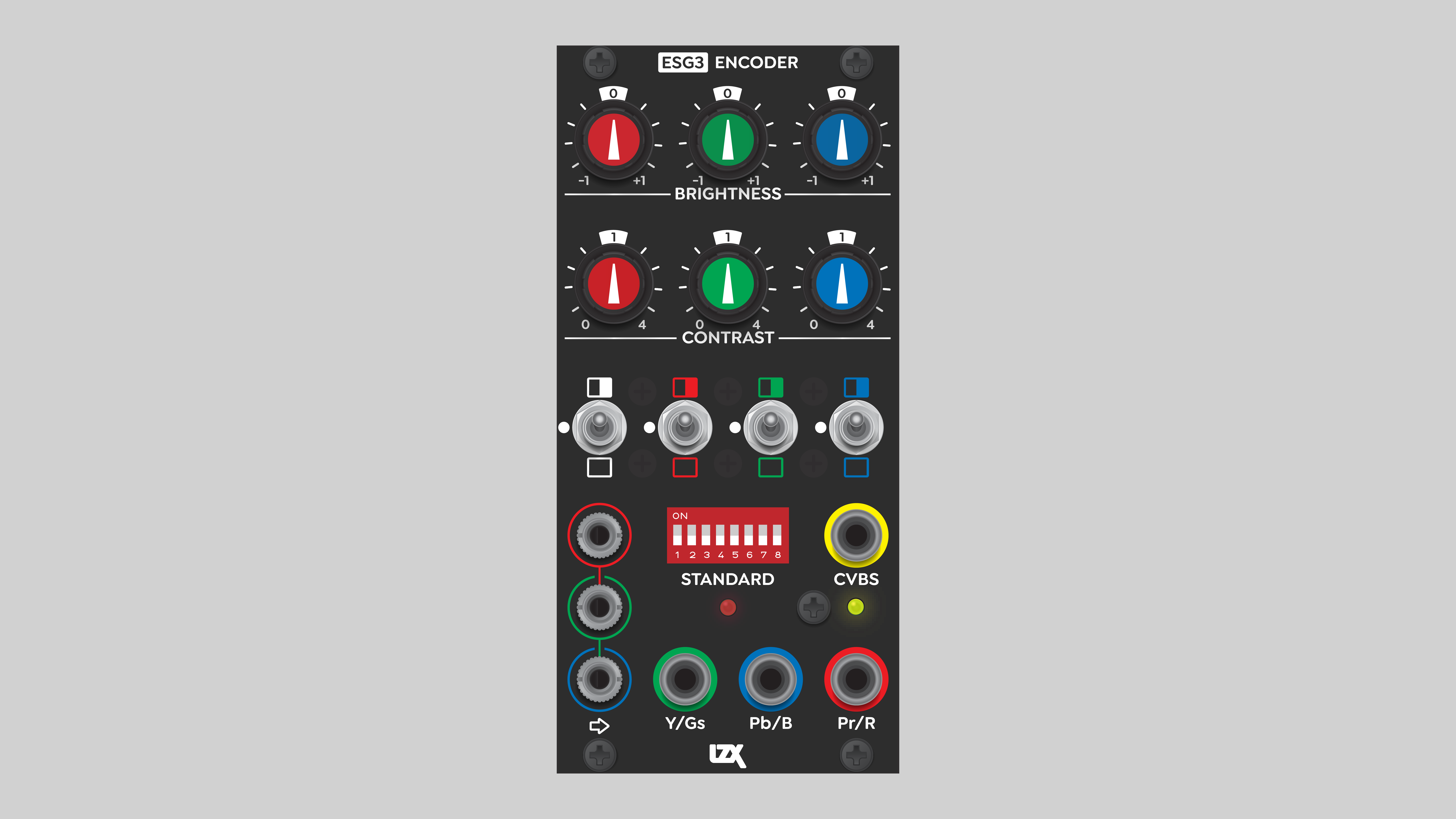
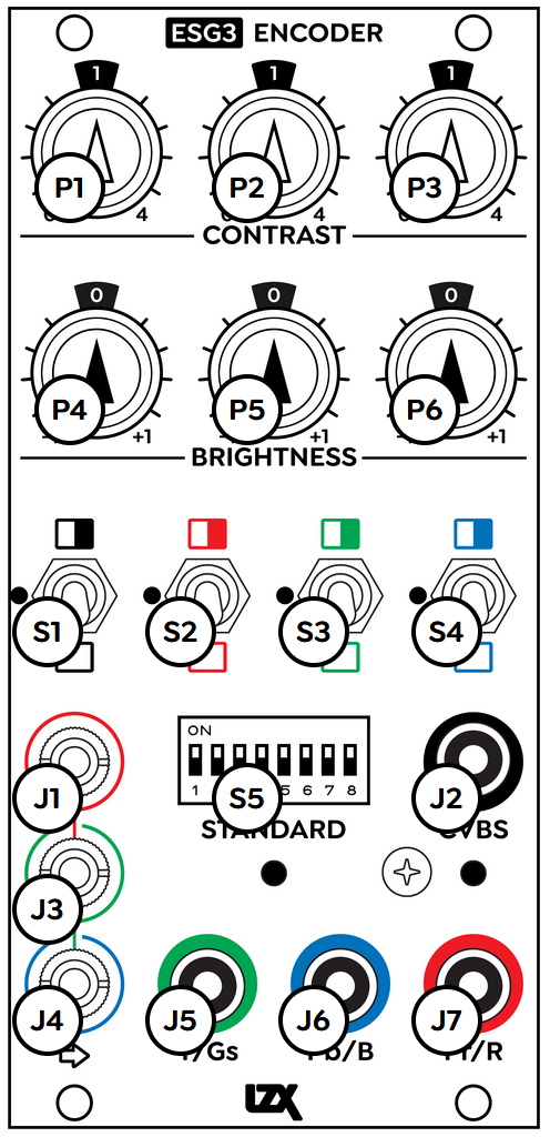
Jacks, pots, and switches
On the bottom left of the module are three input jacks to accept 1v LZX modular video. They are color-coded to accept red, green, and blue color components. Anything patched into a Red, Green, or Blue input is converted to the corresponding color component of a video image.
Inputs are internally normalled, allowing signals to cascade down to the inputs below. Patching a signal into only the top (Red) input sends that signal to all three inputs. If the Contrast and Brightness controls are set to unity gain and bias, then patching into only the Red input results in a grayscale output.
ESG3 only accepts signals in the unipolar range of 0 to 1 volts. Any signal below 0v or above 1v is discarded.
Component video outputs appear at RCA jacks at the bottom right of the module. In YPbPr modes, the order of outputs from left to right is Y, Pb (Blue minus Y), and Pr (Red minus Y). In RGB modes, the order of outputs from left to right is Green, Blue, and Red.
In standard definition modes, composite video output is available from the RCA jack labeled CVBS, color-coded with a yellow insulator inside the jack.
In standard definition modes, both composite and component outputs are simultaneously active. In high definition modes, the composite output is not active.
ESG3 features four toggle switches, each with three positions, to invert or mute individual RGB components, or the global outputs.
At the top of the module are six potentiometer knobs, controlling the Contrast and Brightness of each RGB channel.
To the left of each RGB switch are two small recessed trim potentiometers. These are calibration controls. Their usage is described in the Calibration section below.
Early production units of ESG3 featured detent knob positions. For those units, calibration is more important because the knobs "want" to go to a center, default value. If the unit isn't calibrated, those default positions result in outputs that aren't at unity gain relative to the signal inputs.
Operation
Switches
At the left is the global switch for All Outputs. In the center position, the video outputs operate normally. In the upper position, all outputs are inverted. In the down position, all outputs are disabled or "muted". Flip the left-most switch down to immediately cut to black.
The remaining three switches control the Red, Green, and Blue components, and are color-coded accordingly. In the center position, the RGB component operates normally. In the upper position, the component is inverted, and in the lower position, the component is disabled or "muted".
Different combinations of switch positions result in various forms of colorization based on the video primaries of red, green, blue, and the secondary colors of cyan, magenta, and yellow. For example, if a signal is patched into the Red input only, and all switches and knobs are in the center positions, the output will be grayscale. Flipping the Blue switch down disables that component, resulting in the mixing of only red and green, which produces a yellow color at the output. Flipping the Blue switch up inverts the blue channel, colorizing the grayscale input to a complementary yellow-blue color palette.
Potentiometer knobs
Various Contrast and Brightness settings can yield results ranging from delicate color correction to extreme posterization effects.
Each of the red, green, and blue color components can be adjusted independently. For each component, ESG3 provides a potentiometer to adjust the Contrast (amplitude/gain) and Brightness (bias/offset). For a properly calibrated ESG3, setting all six knobs to the center, 12 o'clock position results in a setting of unity gain. ESG3 transparently transcodes the input signals to legal video, without adjustment. This is what we need if we wish to preserve the colors of an external video source.
A Contrast pot controls the amplitude or gain of its color component. The scaling operation is centered on a voltage of 0.5, or middle gray. When a Contrast pot is turned fully counterclockwise, the amplitude is zero. If the component's Brightness knob and toggle switch are set to their center, neutral positions, then a static voltage of 0.5 for that color component is sent to the encoding circuit. If all Contrast pots are turned fully counterclocwise, and all other settings are neutral, the output of the encoder is middle gray.
ESG3 can produce interesting posterization effects, similar to a key generator. Increasing Contrast eventually results in soft clipping. If the amplitude of the input signal is pushed beyond the 0 to 1 range, picture information at the top and bottom of the range is discarded. Highlights are blasted out, blacks are crushed.
A Brightness pot sets the bias or offset of its color component. The signal value is shifted up or down. Again, if the resulting signal goes outside of the 0 to 1 range, soft clipping occurs.
Installation
Installation requirements
- EuroRack enclosure
- 12V DC or EuroRack power supply
- 2.1mm DC barrel power cable or a EuroRack power cable (both options included)
- Four M2.5 x 6mm mounting screws, or screws provided or specified by the enclosure manufacturer
- #1 Phillips head screwdriver, or hand tool provided or specified by the enclosure manufacturer
Installation procedure
- Power off and disconnect the EuroRack enclosure's power supply and any attached DC adapters.
- Connect either the EuroRack Power Cable or the DC Barrel Power Cable to the module. Do not connect both Eurorack and DC Barrel power.
- Ensure that no mounting screws are in any holes in the area where you wish to mount the module.
- Carefully test fit the module with its attached power cable in the open space in the EuroRack enclosure. If it is obstructed by the enclosure or any internal assemblies, abort this procedure.
- Connect the disconnected end of the power cable to the power supply.
- Connect the ESG3 sync output to the first module in the sync chain, or to a sync distribution amplifier inside the enclosure, such as Bus 168. If the system includes TBC2, it should receive sync directly from ESG3.
- Optionally connect the ESG3 sync input to an external jack on the front panel or enclosure, or to another sync generator module. Do not connect ESG3 directly to any external device, as that would incur risk of mechanical damage to the module. Do not connect ESG3 sync input to sync output of any module other than a dedicated sync generator, such as another ESG3. Do not connect ESG3 sync input to TBC2 sync output, as that could incur sync stability issues.
- Mount the module to the EuroRack rails using all mounting holes.
- Store the unused cable along with the product box in a safe location.
- Power on the EuroRack enclosure and start patching.
Full Specifications
| Connectors | Controls | |||||||||||||||||||||||||||||||||||||||||||
|---|---|---|---|---|---|---|---|---|---|---|---|---|---|---|---|---|---|---|---|---|---|---|---|---|---|---|---|---|---|---|---|---|---|---|---|---|---|---|---|---|---|---|---|---|
 |
|
|
Technical Data
| Mounting Width | 12 HP |
| Mounting Depth | 42 mm |
| Mounting Hole Count | 4 |
| Power Consumption | 12V @ 300 mA |
| Power Connectors | 16 pin EuroRack ribbon, 2.1mm DC barrel |
| Input Impedance | 100K ohms |
| Output Impedance | 75 ohms |
| Input Protection Range | +/-15V |
| Input Clipping Range | +/-2.5V |
| Output Range | +/-2.5V |
| Module Width | 60.96 mm |
| Module Height | 128.5 mm |
| Product Box Width | 4 in / 101.6 mm |
| Product Box Height | 2 in / 50.8 mm |
| Product Box Depth | 6 in / 152.4 mm |
| Included | DC barrel power cable, EuroRack power cable |
| EuroRack Power Cable Type | 16-pin to 16-pin |
| EuroRack Power Cable Length | 25 cm |
| DC Barrel Power Cable Length | 25 cm |
| RoHS Compliance | Manufactured with lead-free processes |
| Video Sync | Rear RCA in & out |
Calibration
This is analog video synthesis, not broadcast video. The process below may not result in absolutely perfect calibration compared to professional video equipment, but it is more than sufficient for the purposes of video synthesis.
Calibration requirements
- Electronic "tweaker" trim pot adjustment tool, or small "jeweler's" flat head screwdriver
- Color-critical video monitor
- Waveform monitor and vectorscope
- Either hardware test equipment or a video capture card with software are acceptable.
- One free software option is OBS Studio with the Color Monitor plugin.
- LZX-compatible video module capable of generating a horizontal ramp (e.g. TBC2, DSG3, Angles)
- Note: individual modules may have up to 10% variation in output voltage. If possible, choose the module with output closest to the 0 to 1 voltage range.
- Full-field 100% color bars, using one of the following options:
- Decoder accepting color bars video signal
- TBC2 Media Player displaying color bars image
- Horizontal ramp → Ribbons input
Ribbons D0 / D1 / D2 → ESG3 R / G / B respectively
Adjust Ribbons controls until black bar is visible on left, and white bar is visible on right.
Calibration procedure
Calibration is much easier with hardware test equipment that supports RGB component video and external sync reference (genlock). If a waveform monitor and vectorscope that meet those requirements is available, follow procedure #1 below. If not, follow procedure #2.
Procedure #1: with test equipment supporting RGB component video and external sync
- Set test equipment to RGB mode.
- Set ESG3 to RGsB mode.
- Connect ESG3 sync output to test equipment external sync reference (genlock) input. It's not necessary to connect ESG3 sync directy to the test equipment. Sync can go through other modules or devices before reaching the test equipment.
- Patch horizontal ramp into ESG3 Red input.
- Set all Contrast and Brightness pots precisely to their center, 12 o'clock positions. Set all switches to their center positions.
- If test equipment has RGB Parade display mode, activate it. If not, skip to step 9.
- Connect ESG3 RGB outputs to test equipment RGB inputs and monitor.
- Adjust all ESG3 trim pots until all ramps precisely occupy the values from 0 to 100 IRE, with no clipping on left or right. Skip to step 16.
- Connect ESG3 Green output to Green input of test equipment.
- Adjust Green channel Bias and Gain trim pots until the ramp precisely occupies the values from 0 to 100 IRE, with no clipping on left or right.
- Connect ESG3 Red output to Green input of test equipment.
- Adjust Red channel Bias and Gain trim pots until the ramp precisely occupies the values from 0 to 100 IRE, with no clipping on left or right.
- Connect ESG3 Blue output to Green input of test equipment.
- Adjust Blue channel Bias and Gain trim pots until the ramp precisely occupies the values from 0 to 100 IRE, with no clipping on left or right.
- Connect ESG3 RGB inputs to RGB inputs of test equipment and monitor.
- Check the vectorscope. If needed, make very small adjustments to various trim pots to make the dot as small as possible, as close to center as possible.
- Check the results on the waveform monitor. If the ramp is no longer linear, adjust accordingly. The linearity of the ramp on the waveform monitor is the priority.
- Patch color bars into ESG3 RGB inputs. Check the vectorscope. If ESG3 is calibrated, there will be a dot in the center, and a dot in each of the six boxes corresponding to the RGB primary and CMY secondary colors. If necessary, adjust trim pots accordingly.
- Patch the horizontal ramp back into ESG3 Red input. Verify the results on the waveform monitor.
- If necessary, repeat steps until the ramps are linear on the waveform monitor, and colorbars are in the boxes on the vectorscope.
Procedure #2: without test equipment supporting RGB component video and external sync
- Set ESG3 to RGsB mode.
- Connect ESG3 component outputs to test equipment and monitor.
- Patch horizontal ramp into ESG3 Red input.
- Set all Contrast and Brightness pots precisely to their center, 12 o'clock positions. Set all switches to their center positions.
- Connect ESG3 Green output to Green or Y input of test equipment and monitor.
- Adjust Green channel Bias and Gain trim pots until the ramp precisely occupies the values from 0 to 100 IRE, with no clipping on left or right.
- Set ESG3 to YPbPr mode.
- Connect YPbPr outputs to test equipment and monitor.
- Mute the Green and Blue channels. Adjust Red Bias and Gain trim pots until the ramp precisely occupies the values from 0 to 100 IRE, with no clipping on left or right. This may be challenging on the waveform monitor because the Red channel only uses about 1/3 of the value range. It may be easier to gauge using the color-critical video monitor.
- Mute the Red and Green channels and unmute the Blue channel. Adjust Blue Bias and Gain trim pots until the ramp precisely occupies the values from 0 to 100 IRE, with no clipping on left or right. This is even more challenging on the waveform monitor because the Blue channel only uses about 1/10 of the value range. It may be easier to gauge using the color-critical video monitor.
- Unmute all channels. The result should be a nearly perfect grayscale ramp from 0 to 100 IRE.
- Check the vectorscope. If needed, make very small adjustments to various trim pots to make the dot as small as possible, as close to center as possible.
- Check the results on the waveform monitor. If the ramp is no longer linear, adjust accordingly. The linearity of the ramp on the waveform monitor is the priority.
- Patch color bars into ESG3 RGB inputs. Check the vectorscope. If ESG3 is calibrated, there will a dot in the center, and a dot in each of the six boxes corresponding to the RGB primary and CMY secondary colors. If necessary, adjust trim pots accordingly.
- Patch the horizontal ramp back into ESG3 Red input. Verify the results on the waveform monitor.
- If necessary, repeat steps until the ramps are linear on the waveform monitor, and colorbars are in the boxes on the vectorscope.
Maintenance
Keep your module free of dust and debris by performing periodic cleaning. Spots may be cleaned from the frontpanel with a microfiber cloth and isopropyl alcohol or other electronics cleaner.
Hardware Revisions
The hardware revision code is printed on the circuit board visible from the rear of the module.