PROC
Overview
Proc is a triple voltage processor and summing amplifier, providing continuous control over attenuation, inversion, and bias of each of the three channels. It's an essential tool in any modular video system, enabling a long list of creative effects. These include, but are not limited to:
- Duplicate (buffered multiple)
- Generate static voltages
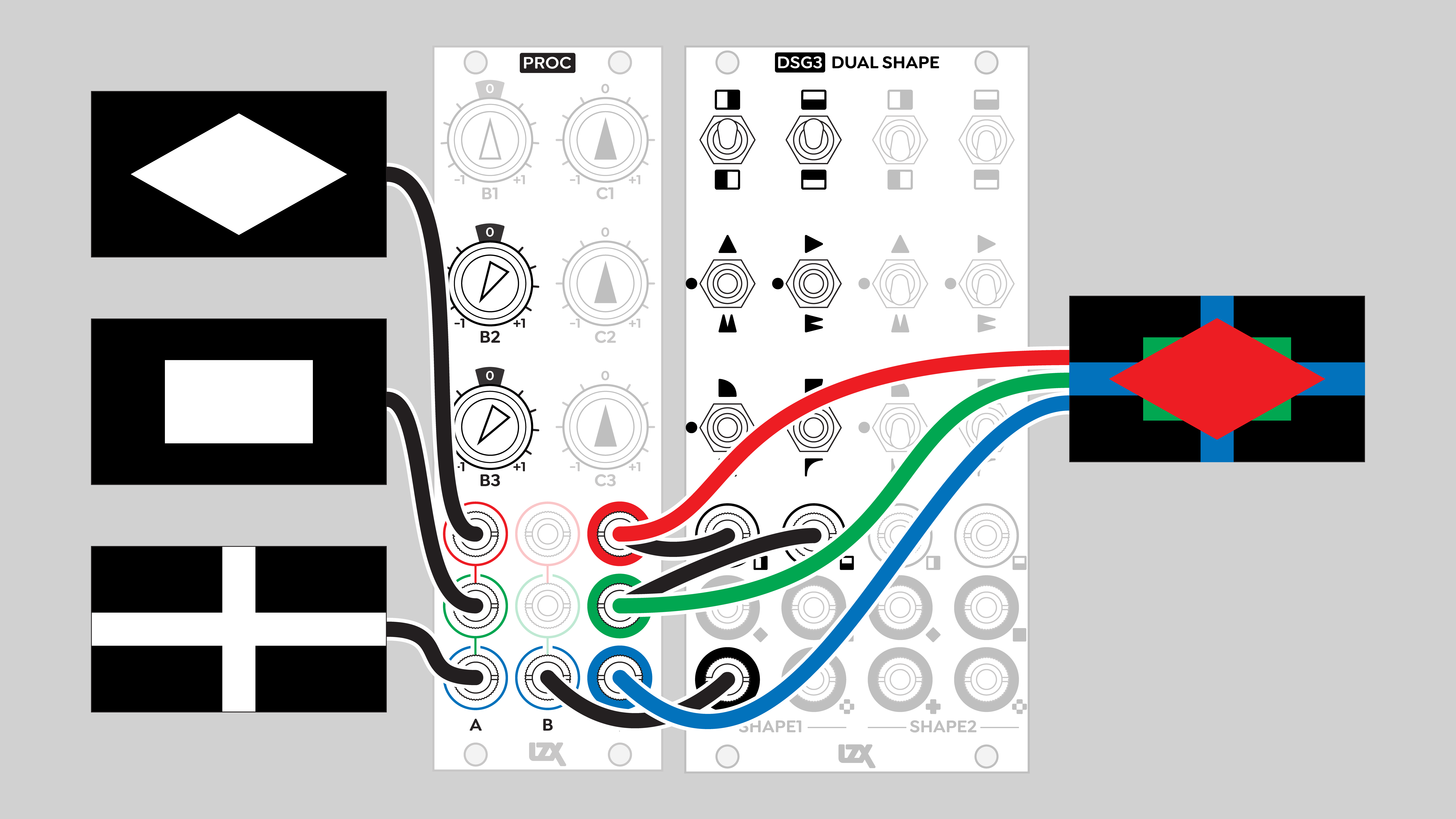
- Pick colors in RGB or YIQ component spaces
- Attenuate or amplify values
- amplitude, gain, contrast, white point
- Raise or lower values
- bias, offset, brightness, black level, pedestal
- Add
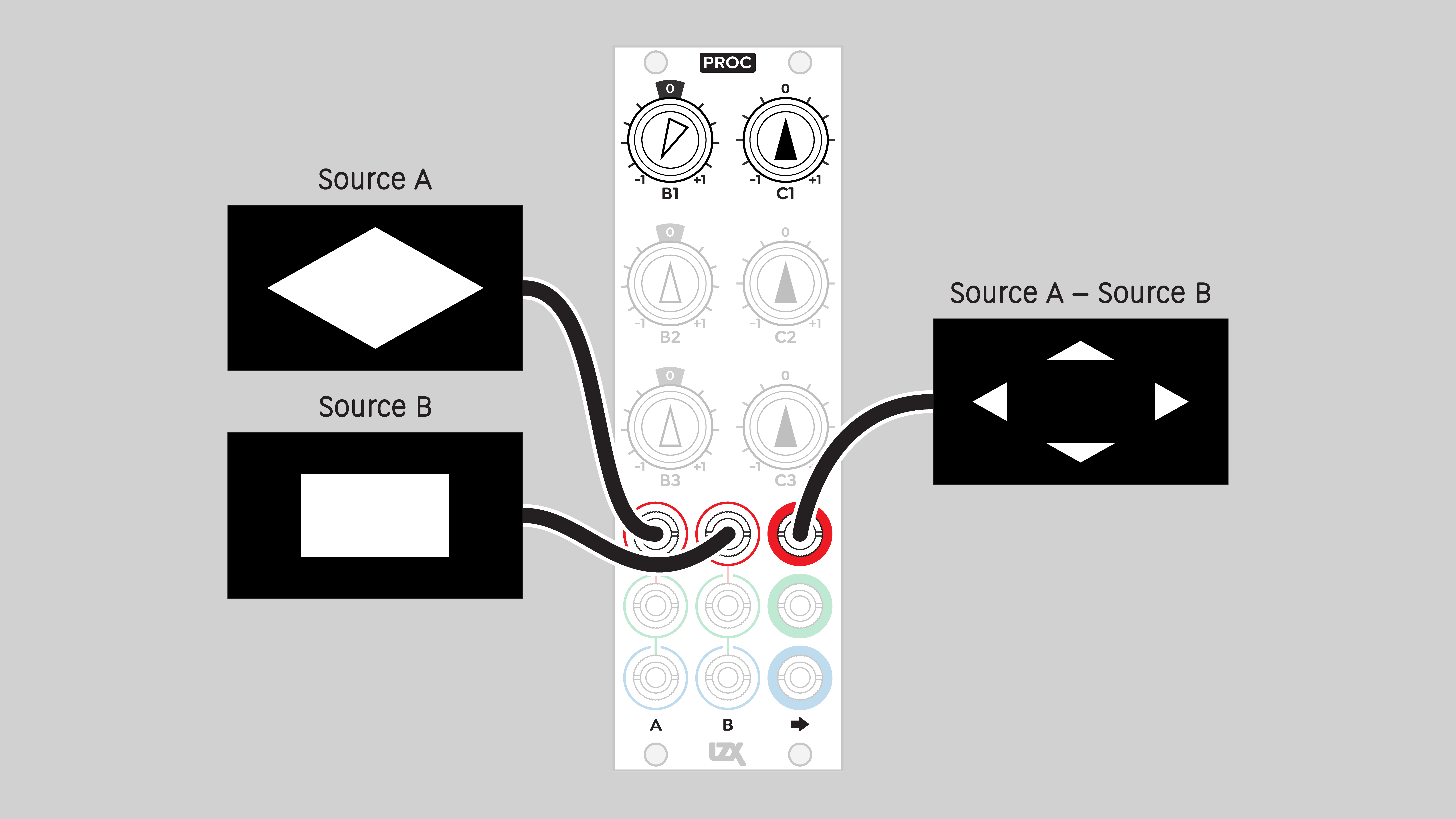
- Subtract
- Mix
- Invert
- Convert between unipolar and bipolar
- Convert RGB to luminance
- Colorize luminance or RGB
Legacy
Proc is the third generation of this module concept. It was preceded by the Visionary series Triple Voltage Processor and the Expedition series Passage modules.
Key Specifications
| Parameter | Value |
|---|---|
| Mounting Width | 8 HP |
| Power Consumption | 12V @ 110 mA |
| Power Connectors | 16 pin EuroRack ribbon, 2.1mm DC barrel |
| Video Sync | None |
| Included | DC barrel power cable, EuroRack power cable |
System Integration Advice
Proc is a fundamental component of any LZX-compatible modular system. It's impossible to overstate the importance of Proc as a general purpose processing tool. Almost every patch uses Proc in some way. It's the "Swiss Army knife" of modular video, performing a wide array of creative and utilitarian functions.
The nature of Proc is so foundational, and its functions so essential, that any system except the very smallest will ultimately need more than one Proc. In modular audio, it's often said that "you can never have enough VCAs". In modular video, you can never have enough Procs. A reasonable rule of thumb is that a system will need one Proc per approximately 100 HP of space.
Proc pairs particularly well with modules capable of handling bipolar signals, such as Swatch. The I and Q color components range between -0.5 and +0.5 volts. Proc can bias the color components up or down, to or from the unipolar range of 0 to +1 volts. This allows I and Q to be processed by modules that can only handle unipolar signals.
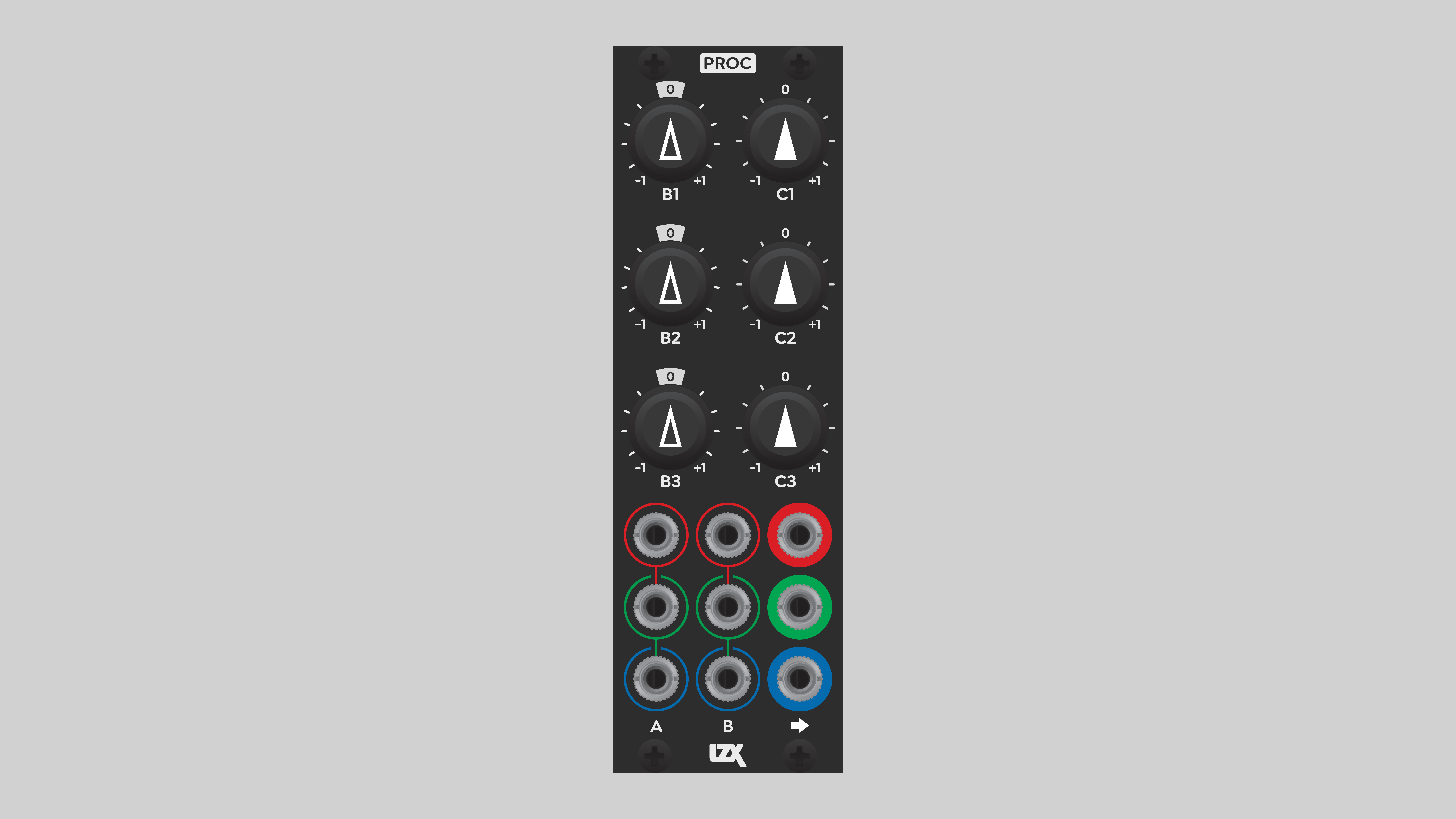
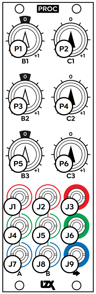
Controls & Connectors
Proc consists of three identical channels. The inputs to each channel are arranged in rows 1, 2, and 3. Rows are color-coded red, green, and blue, respectively, but this is only for convenience. Any video or control signal can be patched into any input.
Each channel has two input jacks, in columns A and B.
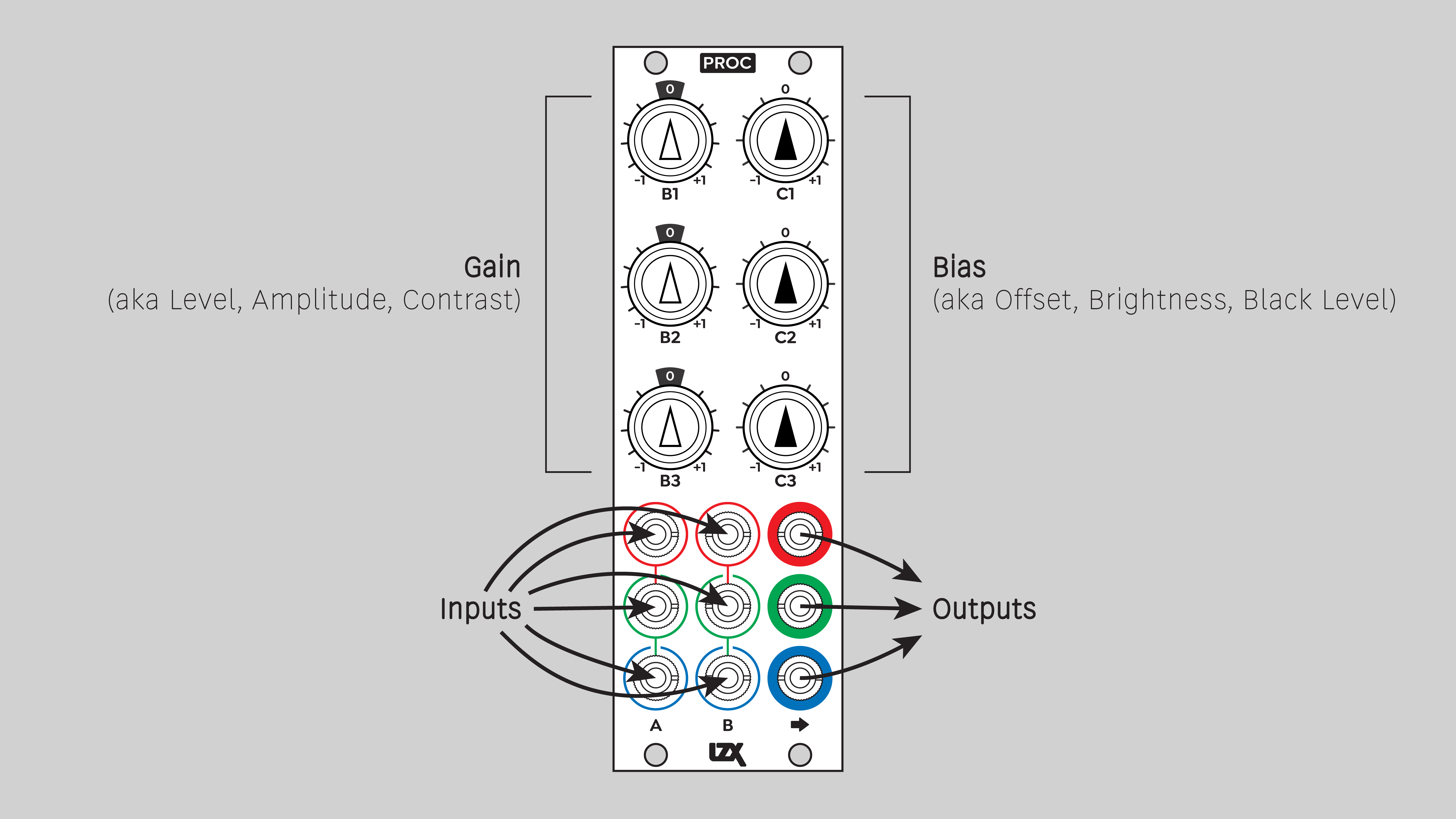
Each channel has two potentiometer knobs, Gain and Bias.
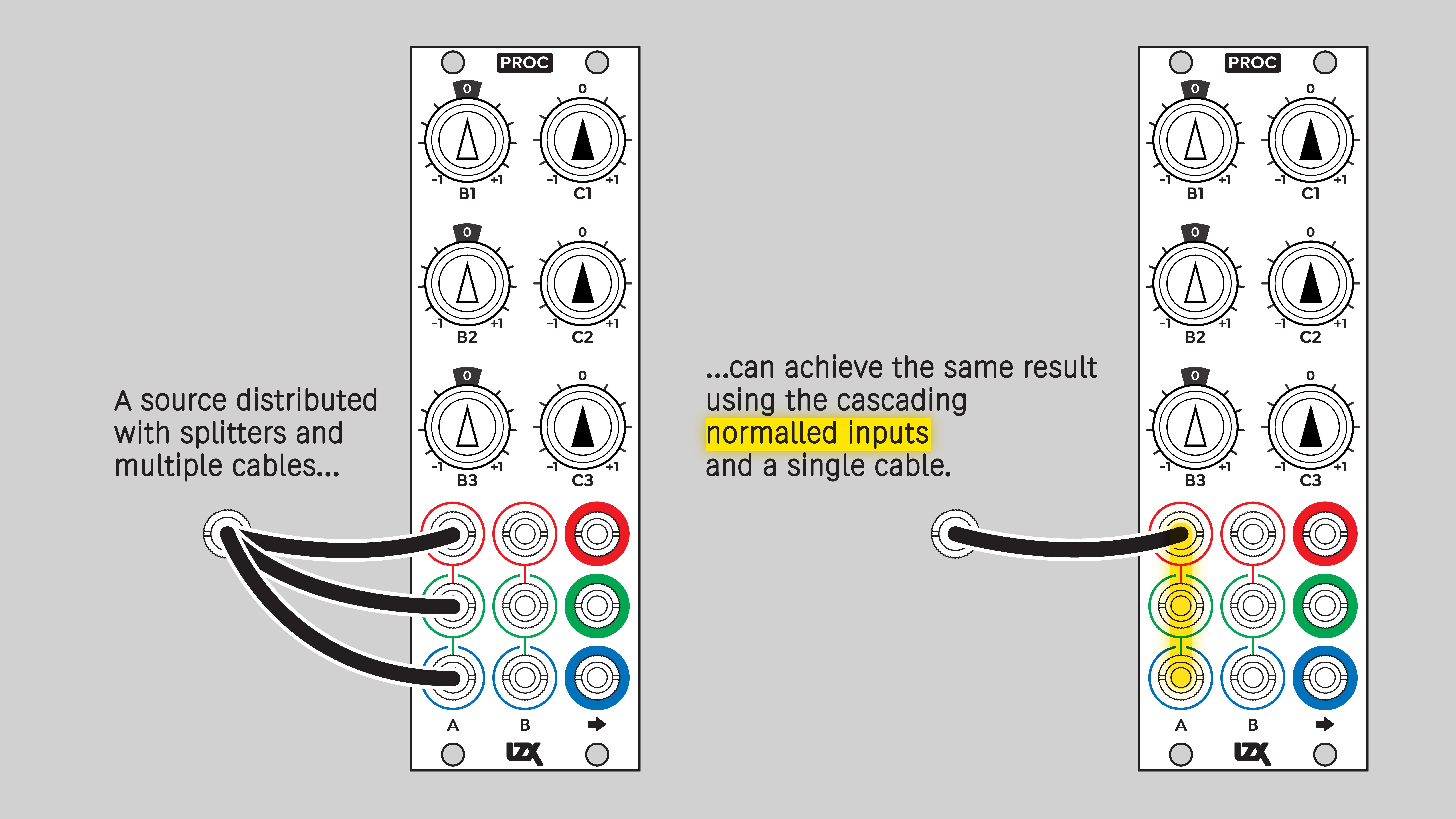
The inputs are internally self-normalled to cascade from top to bottom. A signal patched into a top row input flows to the other inputs in that column.
Operation
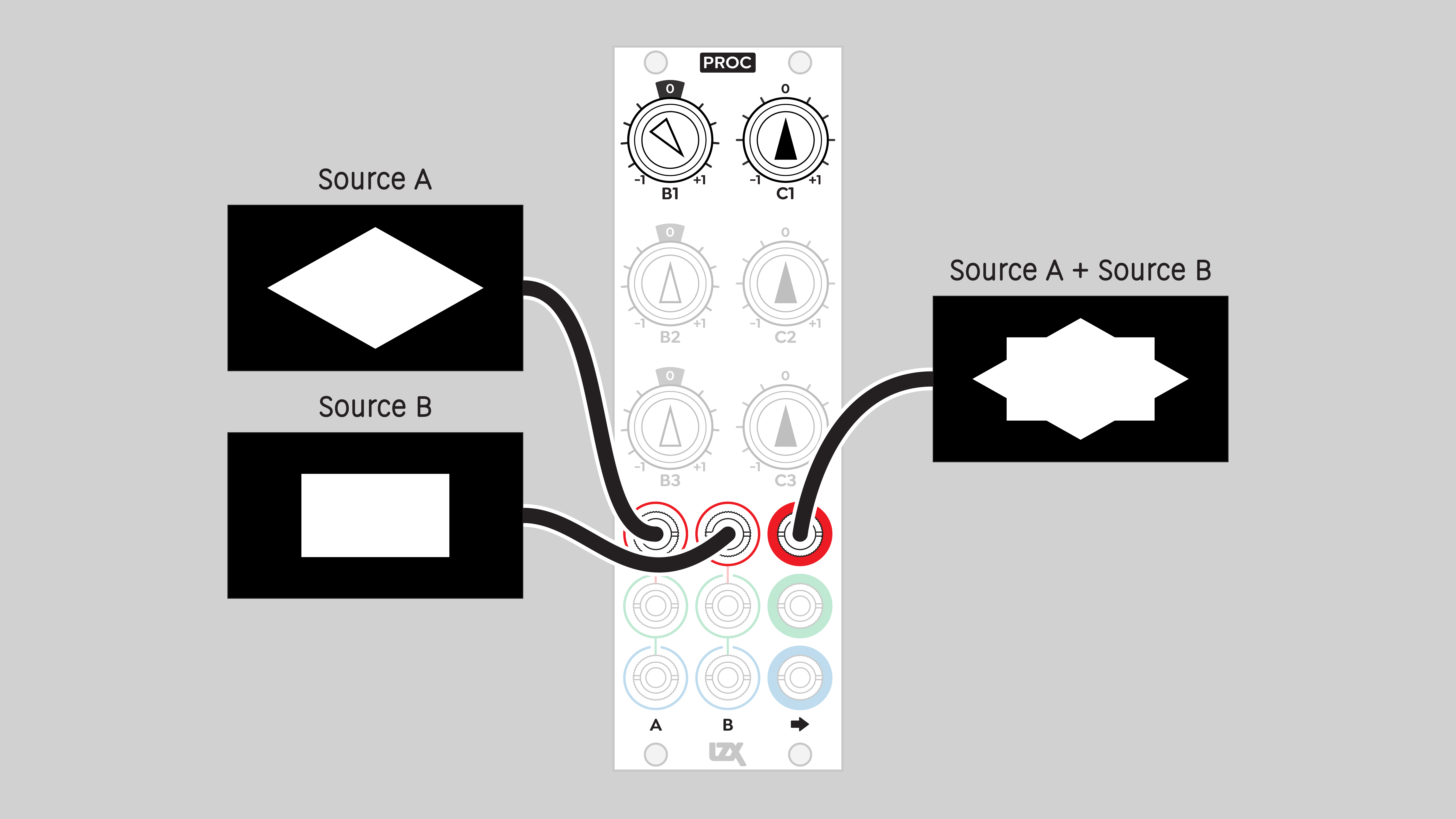
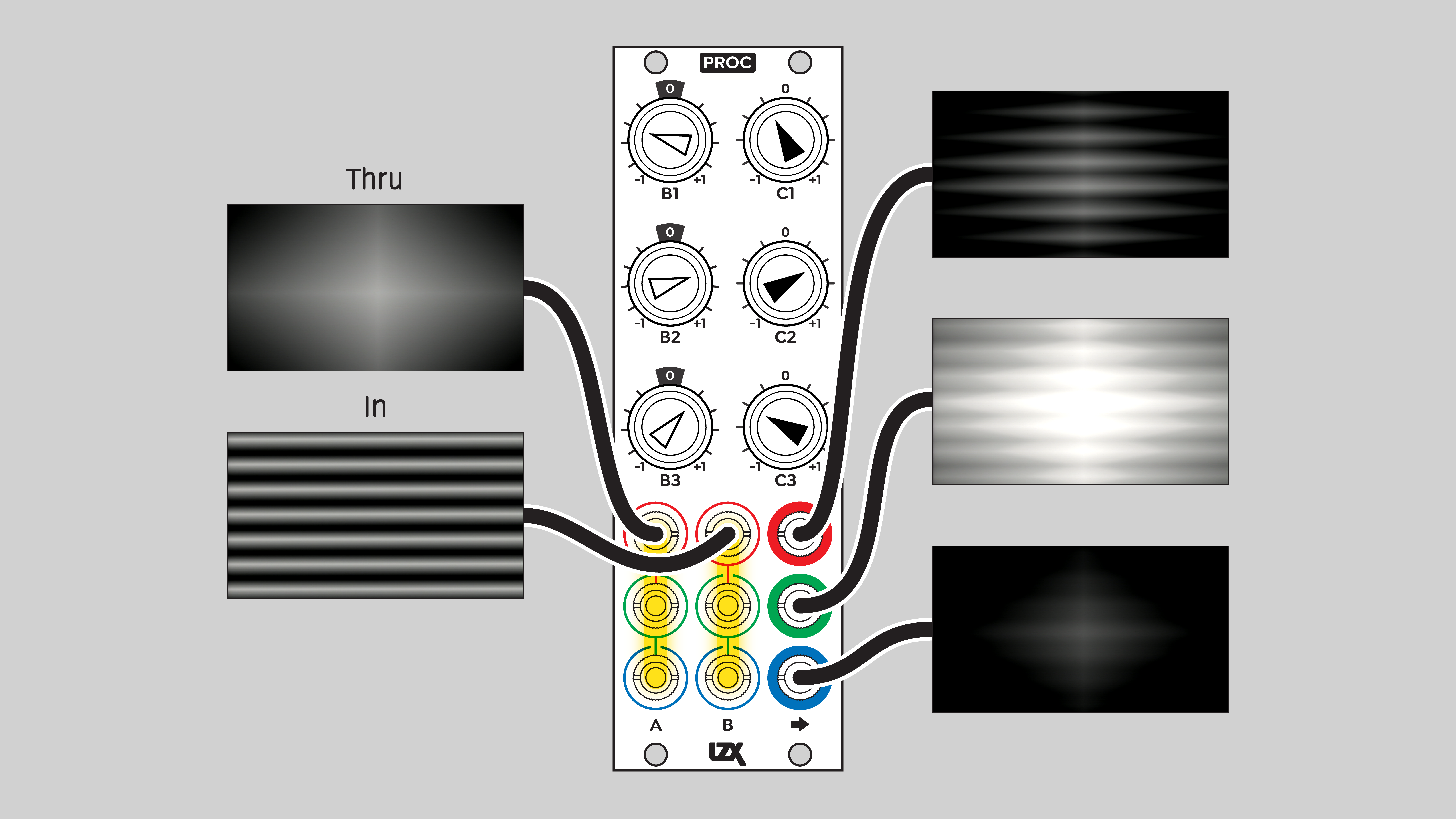
Each channel sums the A and B inputs, plus an internally generated static voltage C. Input A is added without alteration, so it's also known as the Thru input. Input B is multiplied by its corresponding Gain knob before being added. It's also known as the In input.
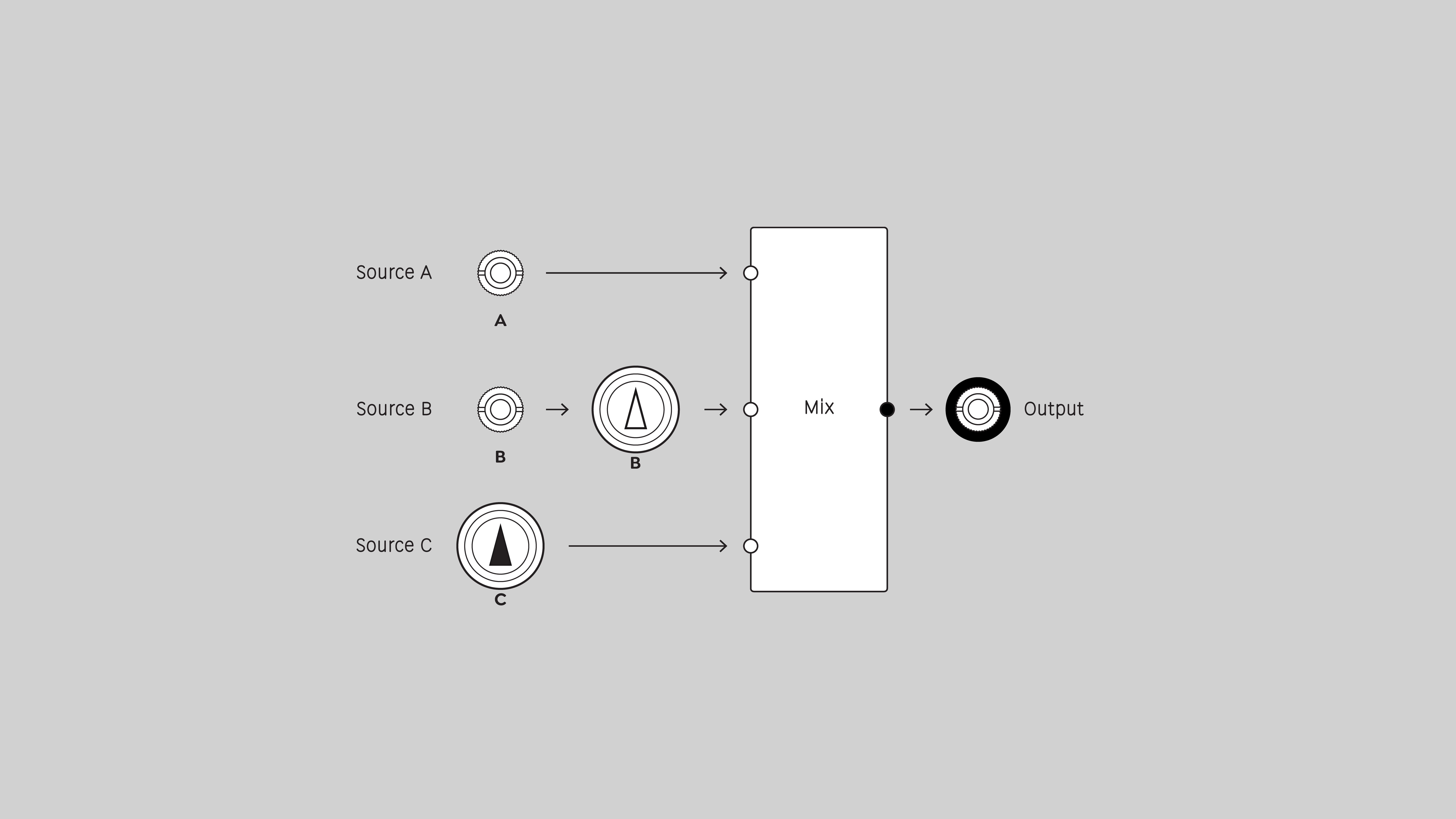
Function block per channel
The output can be expressed the sum of jack A, plus the product of jack B and potentiometer B, plus potentiometer C.
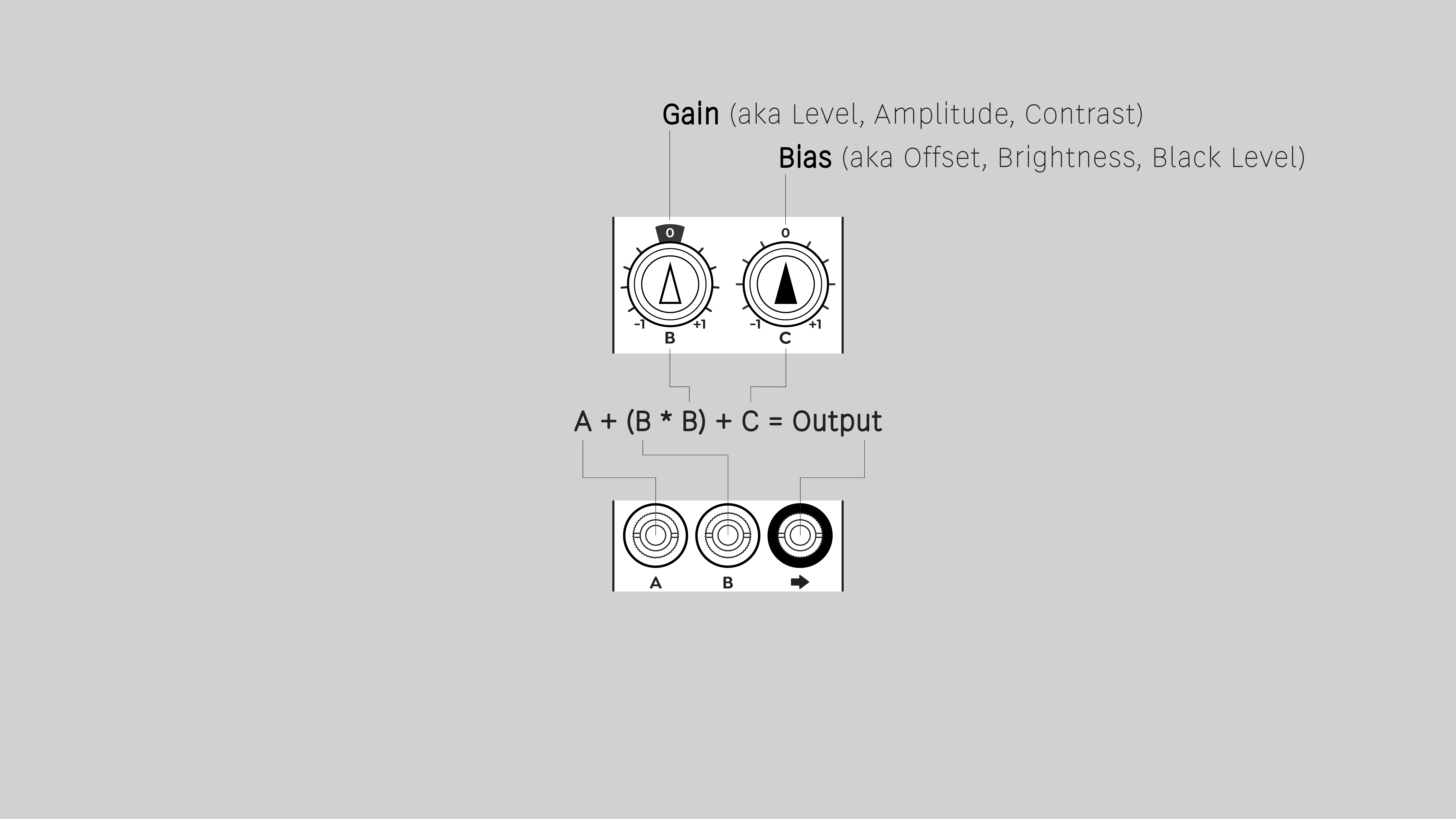
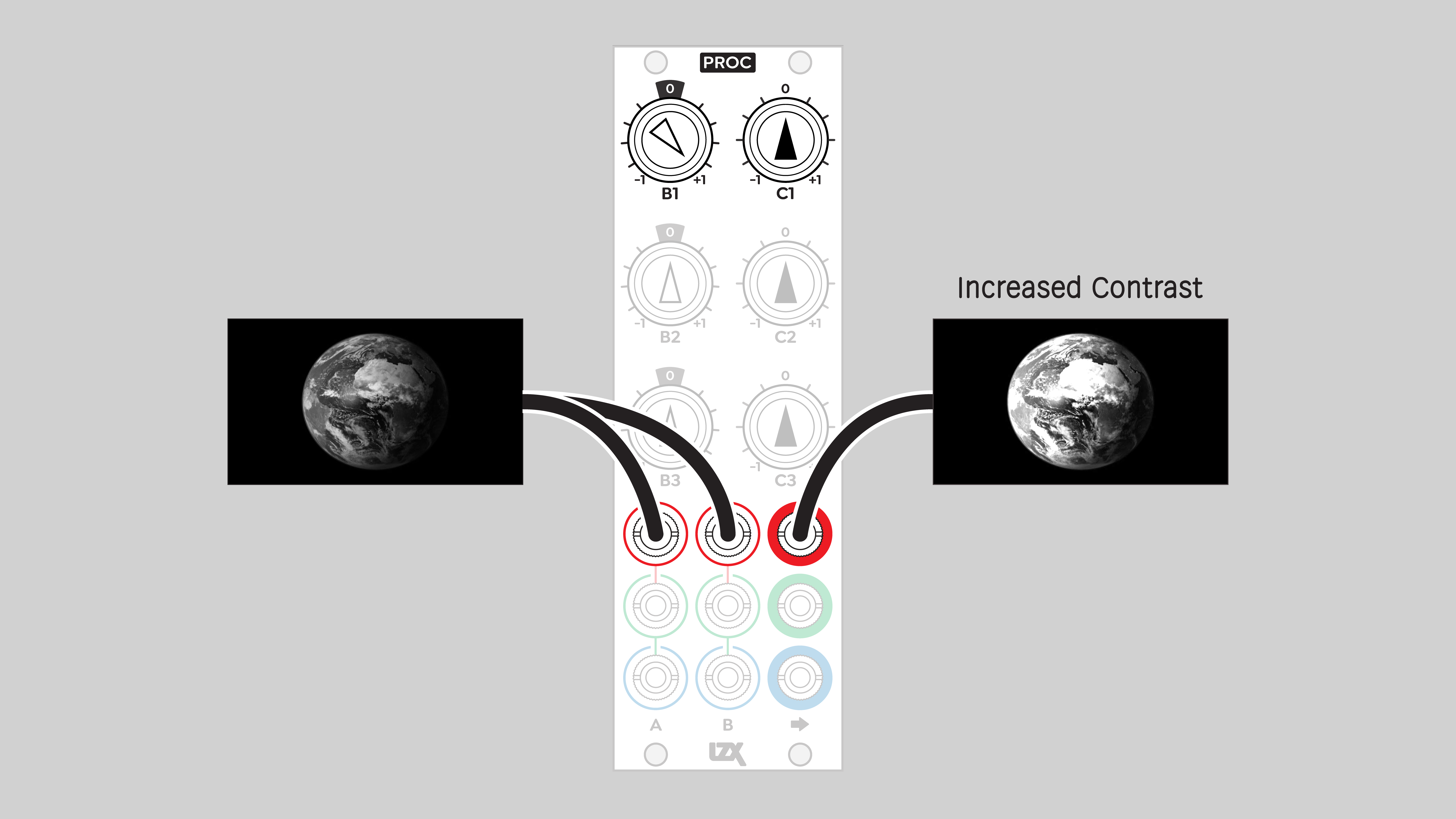
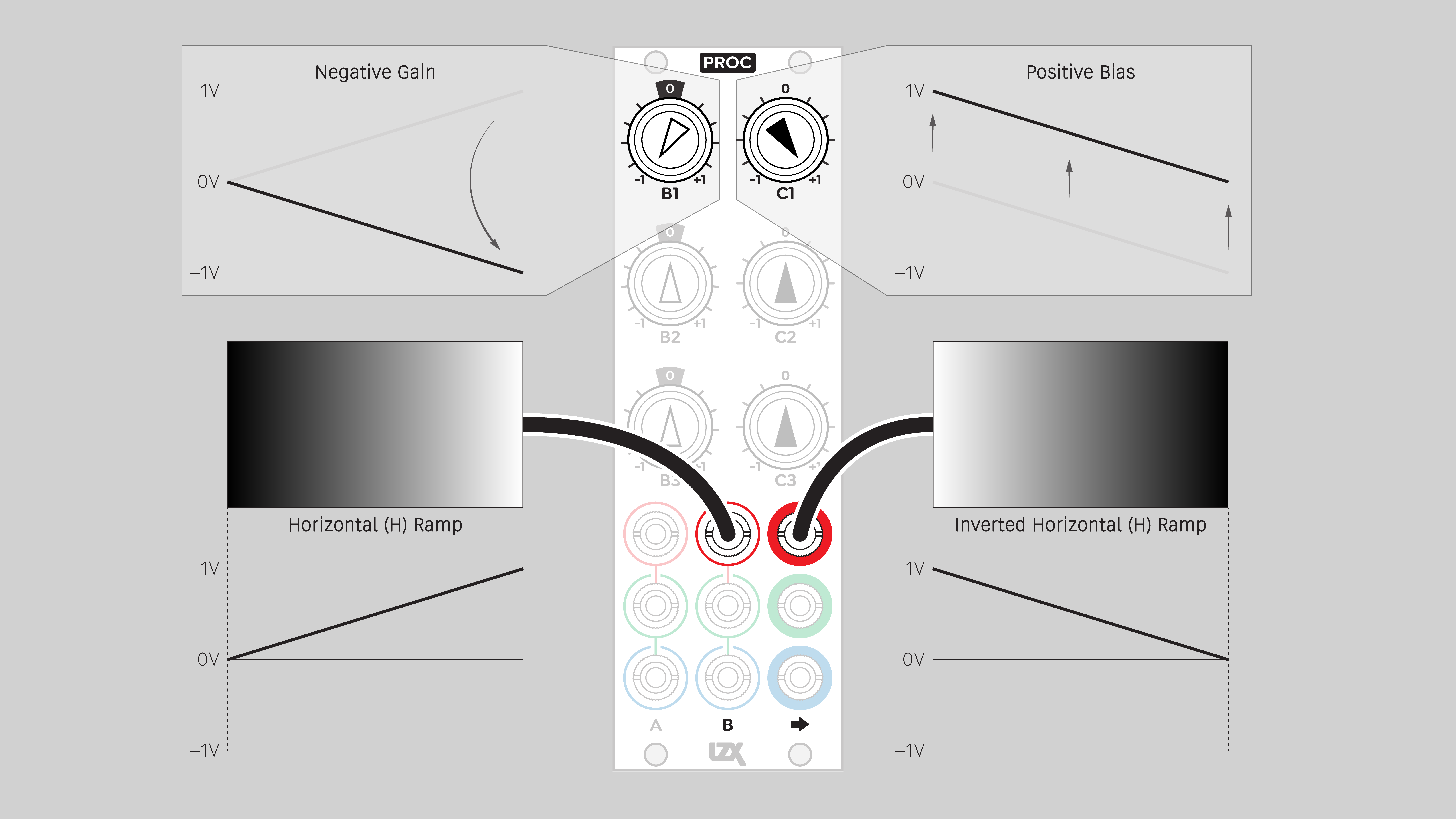
Gain
Each Gain potentiometer, labeled B, can attenuate or invert the value of the signal at the channel's B input. At the 12 o'clock position, the signal is multiplied by zero, so none of the B input signal is added to the output. Turning the knob clockwise to the right of 12 o'clock increases the amplitude up to the full value of the input signal. Turning the knob counterclockwise to the left of 12 o'clock inverts the signal, sending it into the negative voltage range.
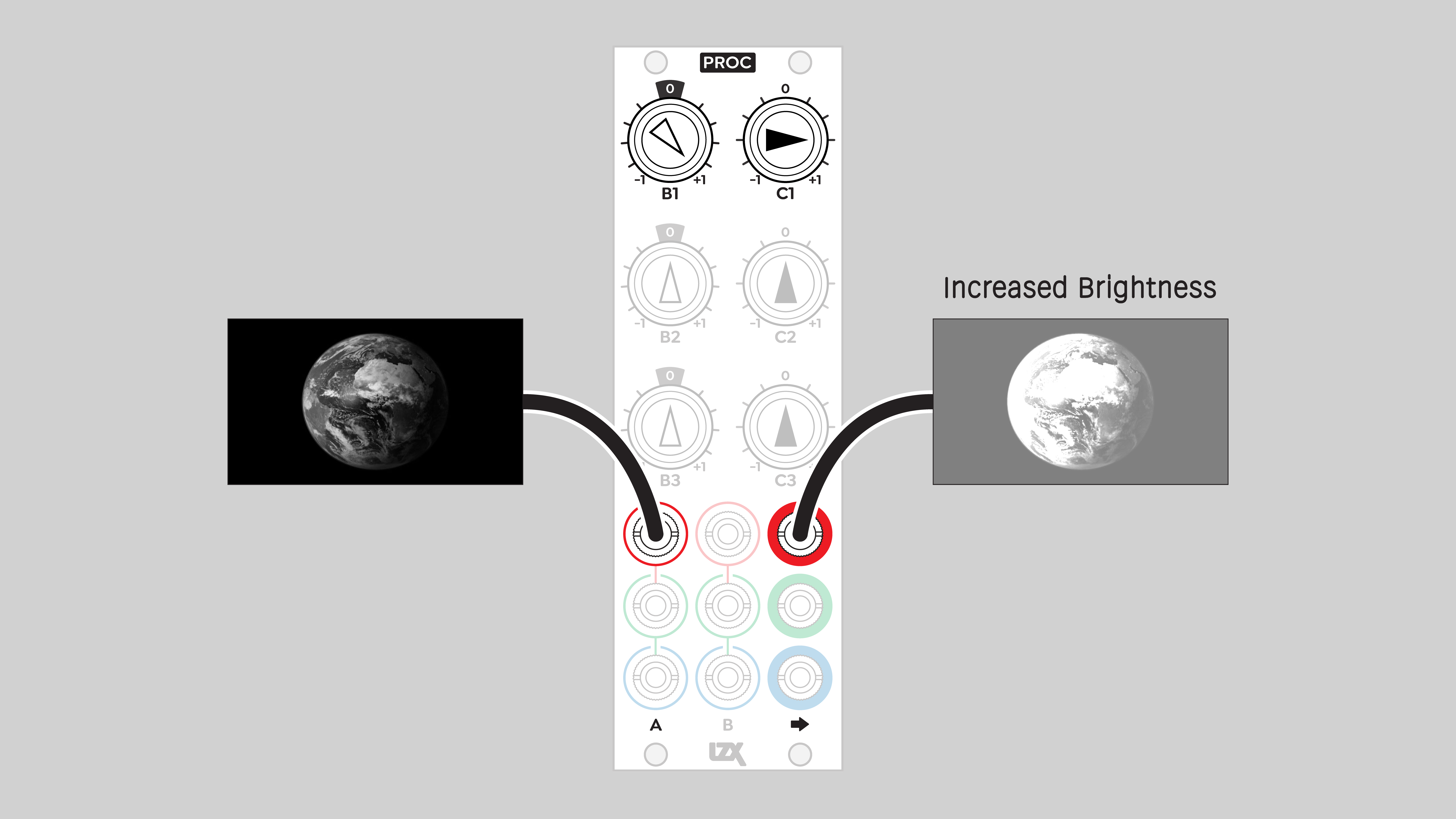
Bias
Each Bias potentiometer, labeled C, adds a static voltage to the output. At the 12 o'clock position, the voltage is zero, so no offset is added to the output. Clockwise rotation to the right of 12 o'clock adds a voltage, biasing the output up. Counterclockwise rotation to the left of 12 o'clock subtracts a voltage, biasing the output down.
Voltage range
Proc can handle input signals that add up to a value range from -2 to +2 volts without distortion. Note that the internally generated bias voltage C is also an input signal, even though there's no C input jack.
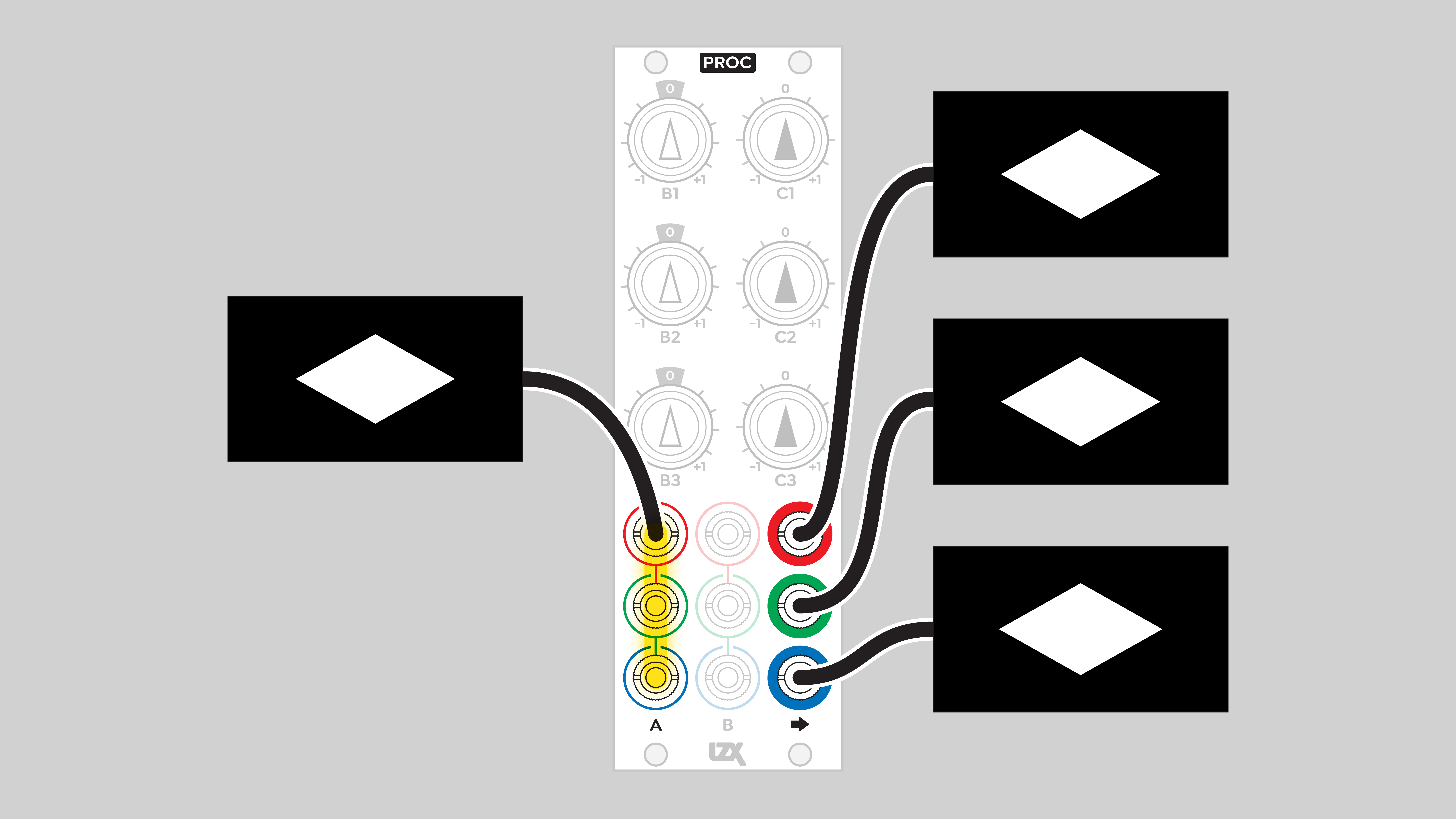
Proc can also output signals in that same range, -2 to +2 volts. This allows for bidirectional conversion between unipolar signals that are only positive, and bipolar signals that can be positive or negative.
As the animation above illustrates, negative voltages are outside the visible range of LZX video. Some modules can handle bipolar signals with negative voltages, but an encoder such as ESG3 can only accept values in the range from 0 to +1 volts. Any value below zero will simply be ignored by the encoder.
Self-patching
By sending the output of one channel to the input of another, we can create more complex effects by combining more than two signals. For example, if we patch output 1 to input A2, and output 2 to to input A3, we can combine up to four signals with the remaining inputs of A1, B1, B2, and B3.
Video Tutorials
3 Patches for Proc
presented by Johnny Woods
LZX Proc: Video Synth Tools & Techniques
presented by Aaron F. Ross
Example Patches
Buffered multiple
Static voltage
RGB color picker
Bias / brightness
Add
Amplify / increase contrast
Subtract
Invert
Mixer: three variations
Priority layering
Installation
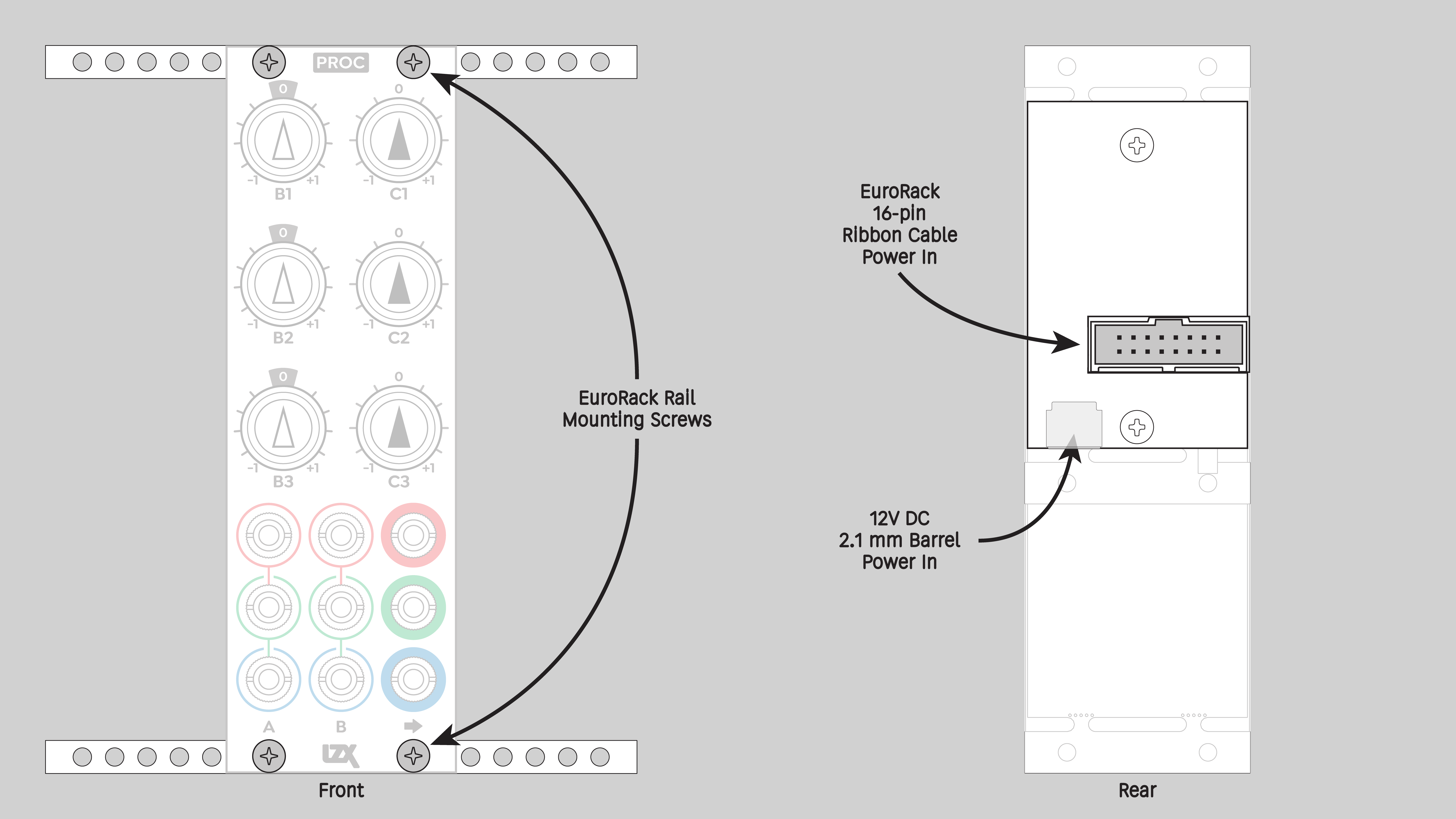
Requirements
- EuroRack enclosure
- 12V DC or EuroRack power supply
- 2.1mm DC barrel power cable or a EuroRack power cable (both options included)
- Four M2.5 x 6mm mounting screws, or screws provided or specified by the enclosure manufacturer
- #1 Phillips head screwdriver, or hand tool provided or specified by the enclosure manufacturer
Procedure
- Power off and disconnect the EuroRack enclosure's power supply and any attached DC adapters.
- Connect either the EuroRack Power Cable or the DC Barrel Power Cable to the module. Do not connect both Eurorack and DC Barrel power.
- Ensure that no mounting screws are in any holes in the area where you wish to mount the module.
- Carefully test fit the module with its attached power cable in the open space in the EuroRack enclosure. If it is obstructed by the enclosure or any internal assemblies, abort this procedure.
- Connect the disconnected end of the power cable to the power supply.
- Mount the module to the EuroRack rails using all mounting holes.
- Store the unused cable along with the product box in a safe location.
- Power on the EuroRack enclosure and start patching.
Full Specifications
| Connectors | Controls | |||||||||||||||||||||||||||||||||||
|---|---|---|---|---|---|---|---|---|---|---|---|---|---|---|---|---|---|---|---|---|---|---|---|---|---|---|---|---|---|---|---|---|---|---|---|---|
 |
|
|
Technical Data
| Parameter | Value |
|---|---|
| Manufacturer Part Number | 950048 |
| Mounting Width | 8 HP |
| Mounting Depth | 32 mm |
| Mounting Hole Count | 4 |
| Power Consumption | 12V @ 110 mA |
| Power Connectors | 16 pin EuroRack ribbon, 2.1mm DC barrel |
| Input Impedance | 1M ohms |
| Output Impedance | 75 ohms |
| Input Protection Range | +/-20V |
| Input Clipping Range | +/-2.5V |
| Output Range | +/-2.5V |
| Included | DC barrel power cable, EuroRack power cable |
| EuroRack Power Cable Type | 16-pin |
| EuroRack Power Cable Length | 25 cm |
| DC Barrel Power Cable Length | 25 cm |
| RoHS Compliance | Manufactured with lead-free processes |
| Video Sync | None |
Maintenance
Keep the module free of dust and debris by performing periodic cleaning. Spots may be cleaned from the front panel with a microfiber cloth and isopropyl alcohol or other electronics cleaner.
Hardware Revisions
The hardware revision code is printed on the circuit board visible from the rear of the module.