KEYCHAIN
Overview
Keychain extracts sharp-edged stencil shapes from video images or patterns. It generates hard keys in standard or high definition using voltage comparators with a response time of only seven nanoseconds!
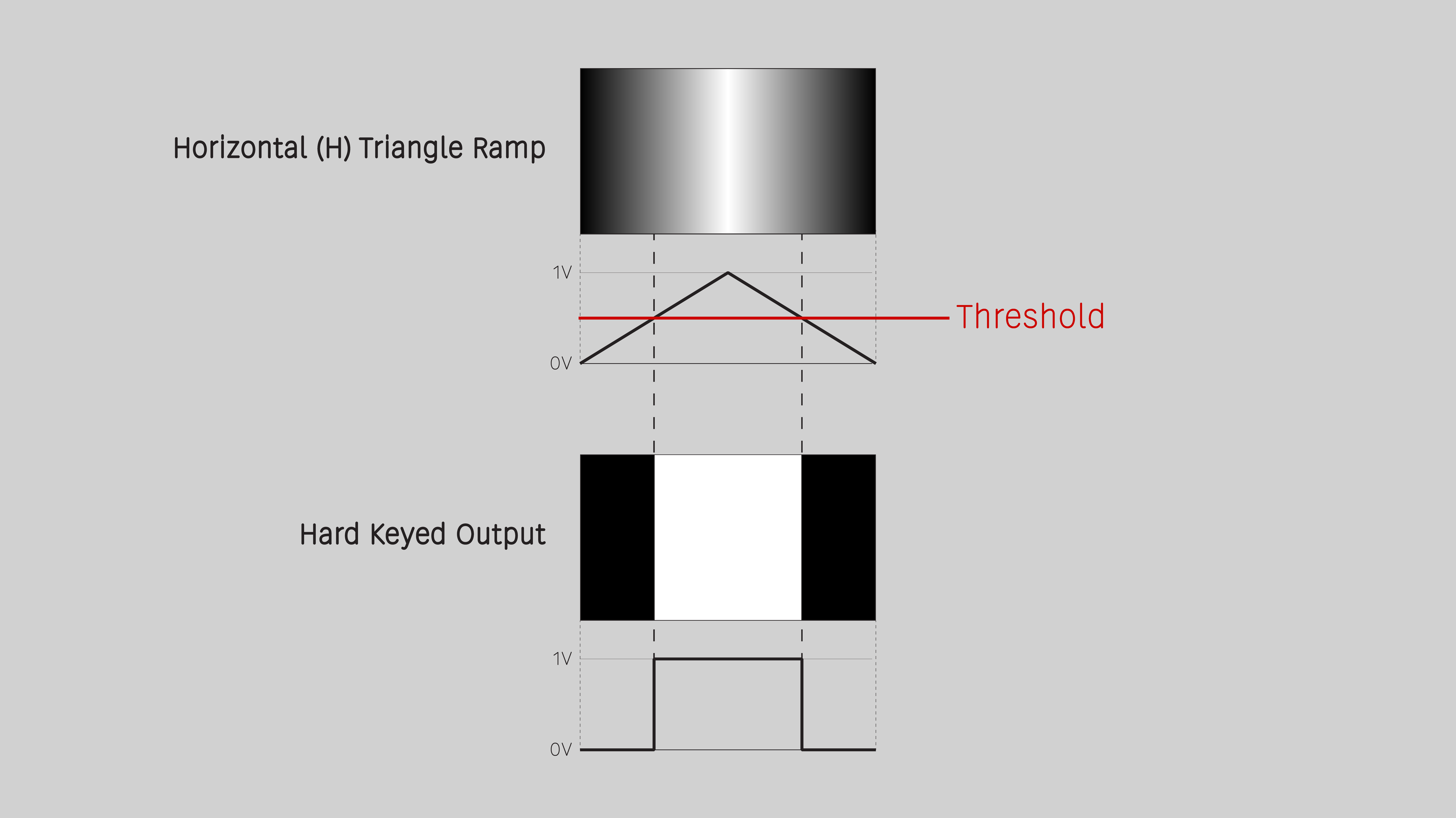
One of Keychain's killer apps is generating animated wipe patterns from grayscale gradients. The simplest example is a ramp, or a mutated ramp from a pattern source such as DSG3. But any grayscale image is fair game, so go wild and crazy with novel, unique, and unexpected wipe shapes!
Keychain is also useful for processing low frequency signals such as LFOs and noise sources, converting any waveform into a square wave or variable width pulse. This is useful for animating hard cuts of varying durations with modules such as Switcher.
Keychain is not a compositor. By itself, it can't combine a foreground and background. For a soft key, or an all-in-one solution, the best option is FKG3.
Key Specifications
| Mounting Width | 8 HP |
| Power Consumption | 12V @ 110 mA |
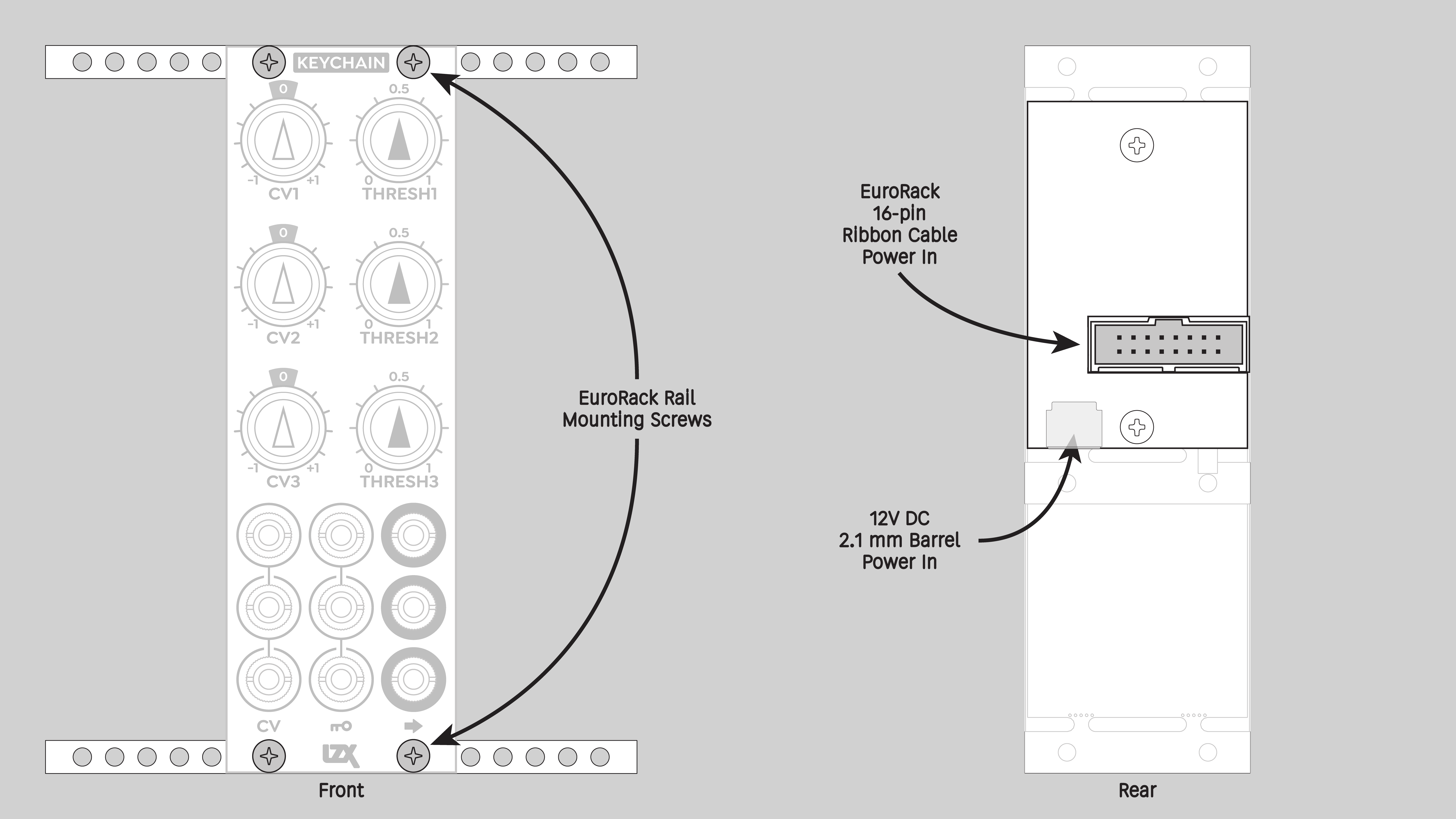
| Power Connectors | 16 pin EuroRack ribbon, 2.1mm DC barrel |
| Video Sync | None |
| Included | DC barrel power cable, EuroRack power cable |
System Integration Advice
Keychain's outputs can be used directly. For example, Keychain's outputs can provide RGB channels to ESG3. In combination with ESG3's proc amp controls, this simple patch is a three-level posterizer.
The full power of Keychain is unleashed in systems that include other core modules, such as DSG3, SMX3, DWO3, and Proc. Keychain is an essential building block of more complex patches involving layered imagery and/or instantaneous transitions such as hard cut edits.
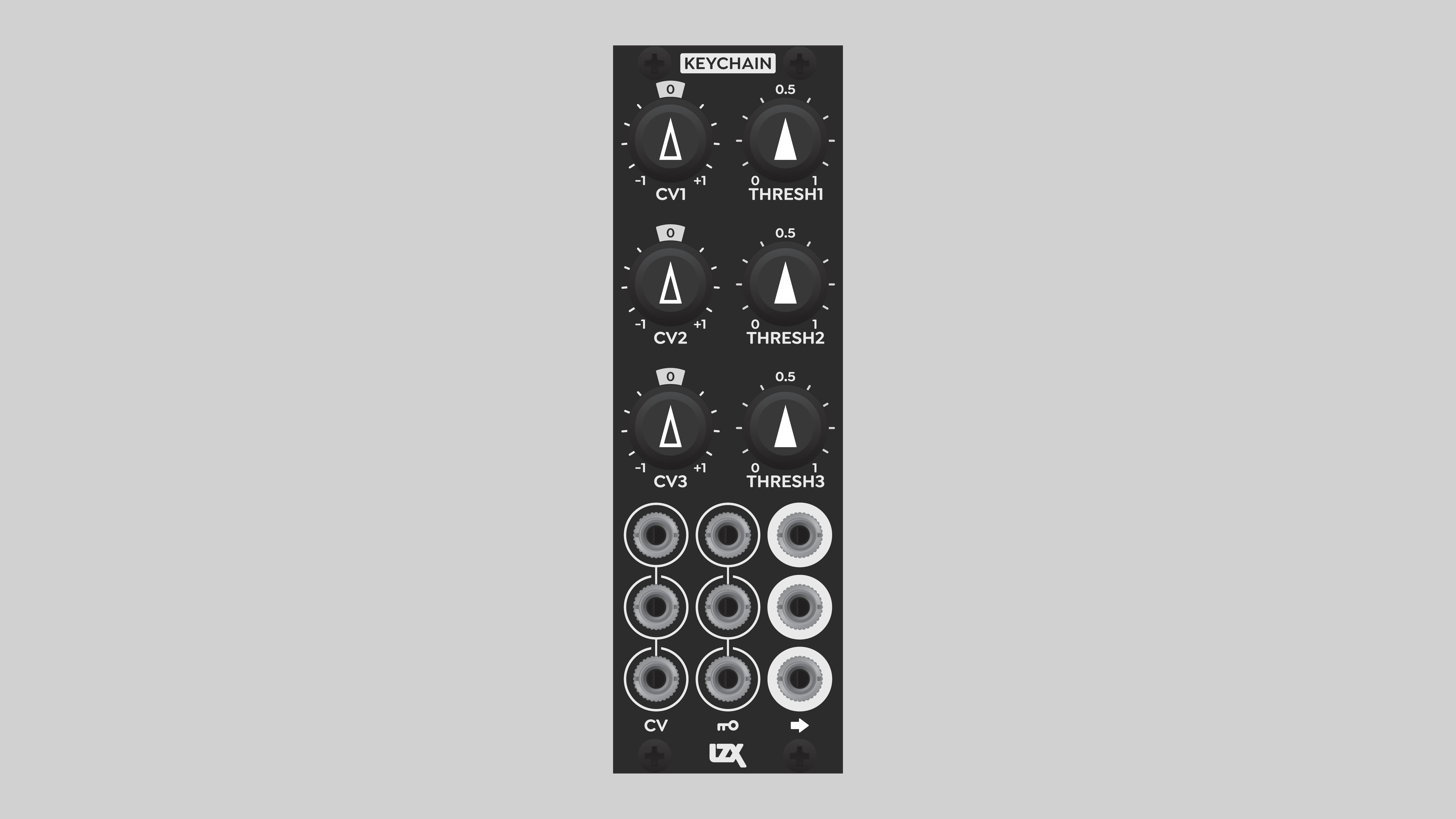
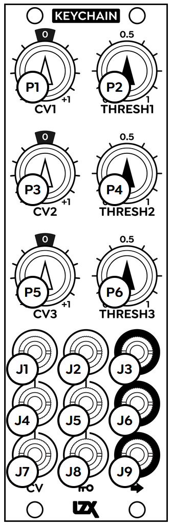
Controls & Connectors
Keychain consists of three independent channels, 1, 2, and 3.
Each channel outputs a one-bit signal with values of zero or one volts.
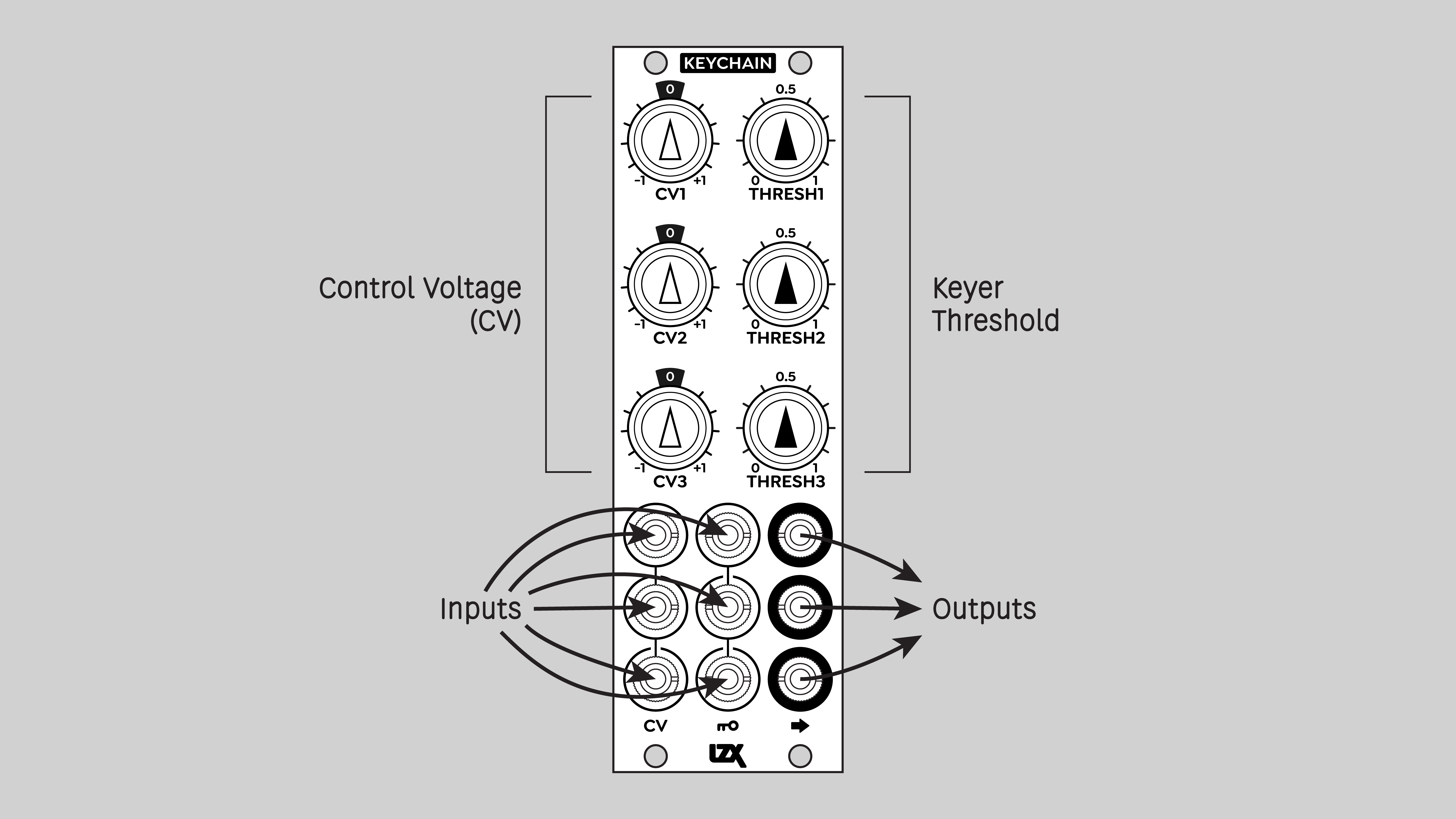
Each channel has two inputs, one labeled CV and one with a Key icon. The threshold of the key is set by the combination of the inputs and the Thresh potentiometer knob.
The gain of each CV input is adjusted with its attenuverter potentiometer knob, labeled CV. At the twelve o'clock position, the CV signal is multiplied by zero, nullifying it. Turning the CV knob clockwise, to the right of 12 o'clock, increases the CV gain up to its full intensity. Turning the CV knob counter-clockwise, to the left of 12 o'clock, inverts the incoming CV signal.
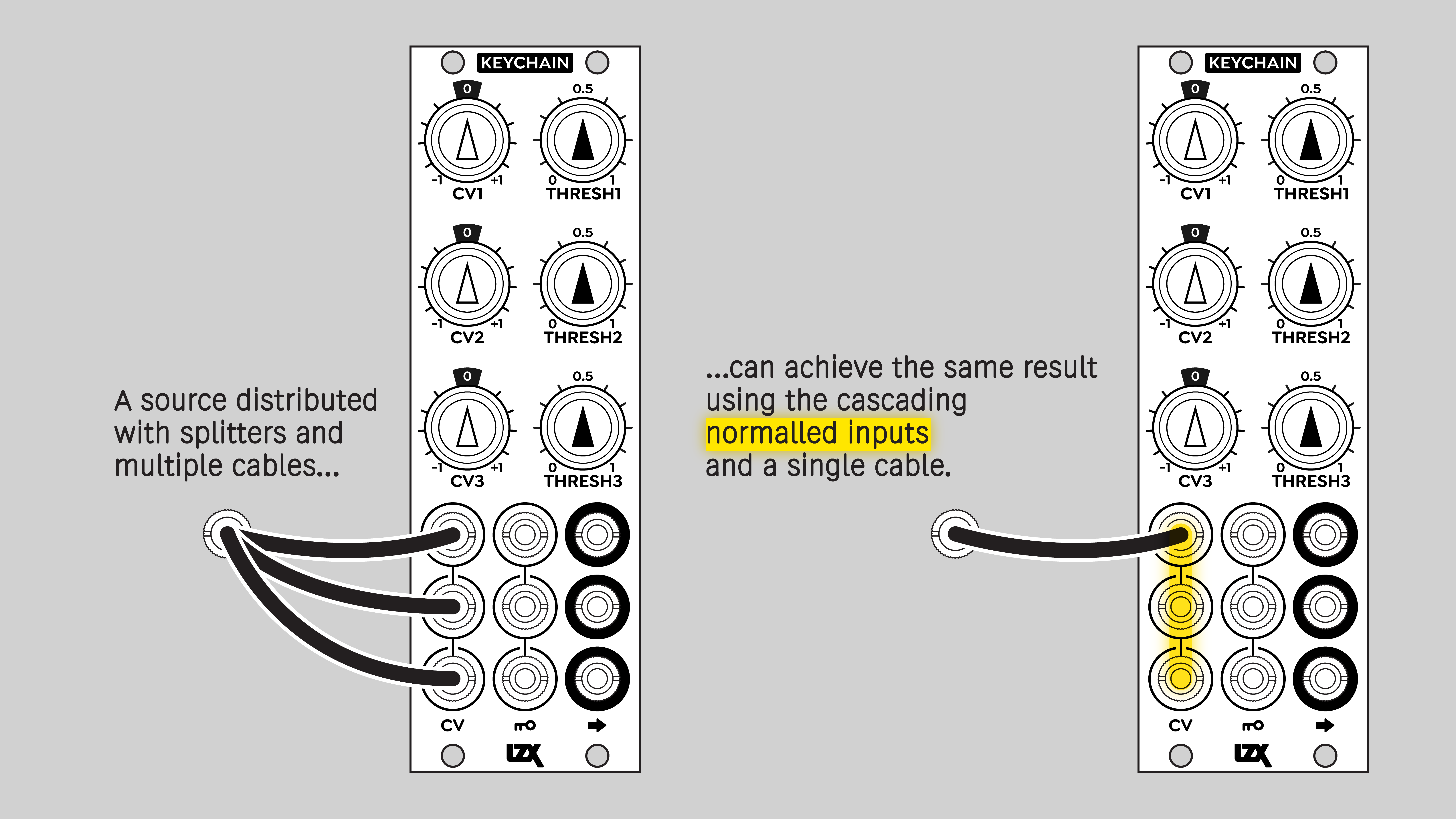
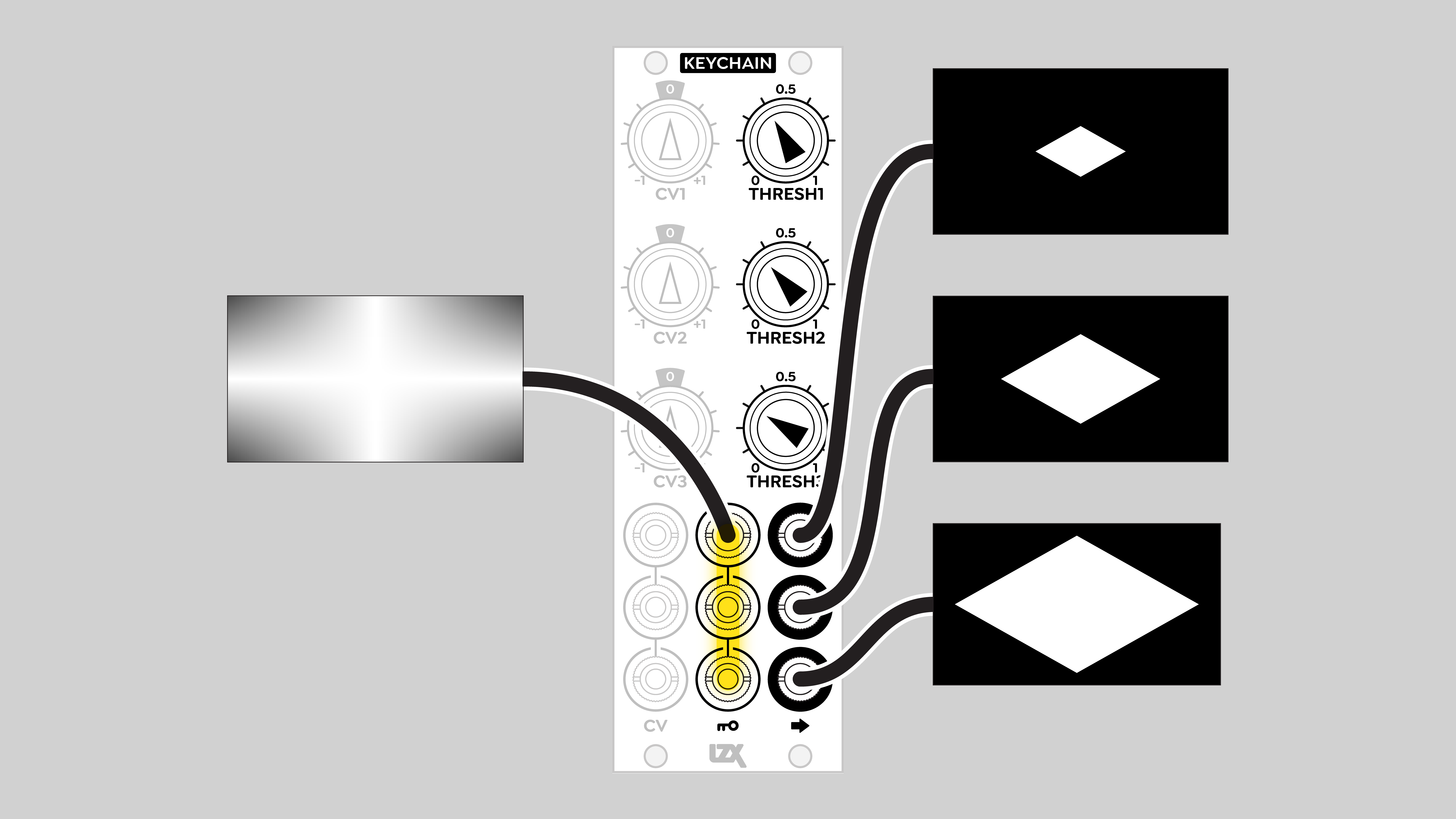
Both sets of inputs are internally self-normalled, allowing a signal patched into a channel 1 input to flow to the corresponding inputs of the other channels.
Operation
Internally, each Keychain channel consists of a mixer and a comparator. The mixer architecture is similar to Proc. A signal patched into a Key input is passed to the mixer without adjustment. A signal patched into a CV input is multiplied by its attenuverter potentiometer before being passed to the mixer. These two inputs are summed along with a third signal: a static voltage controlled by the Thresh potentiometer knob. Unlike the Bias control on Proc, the Threshold control is unipolar, ranging from zero to +1 volts.
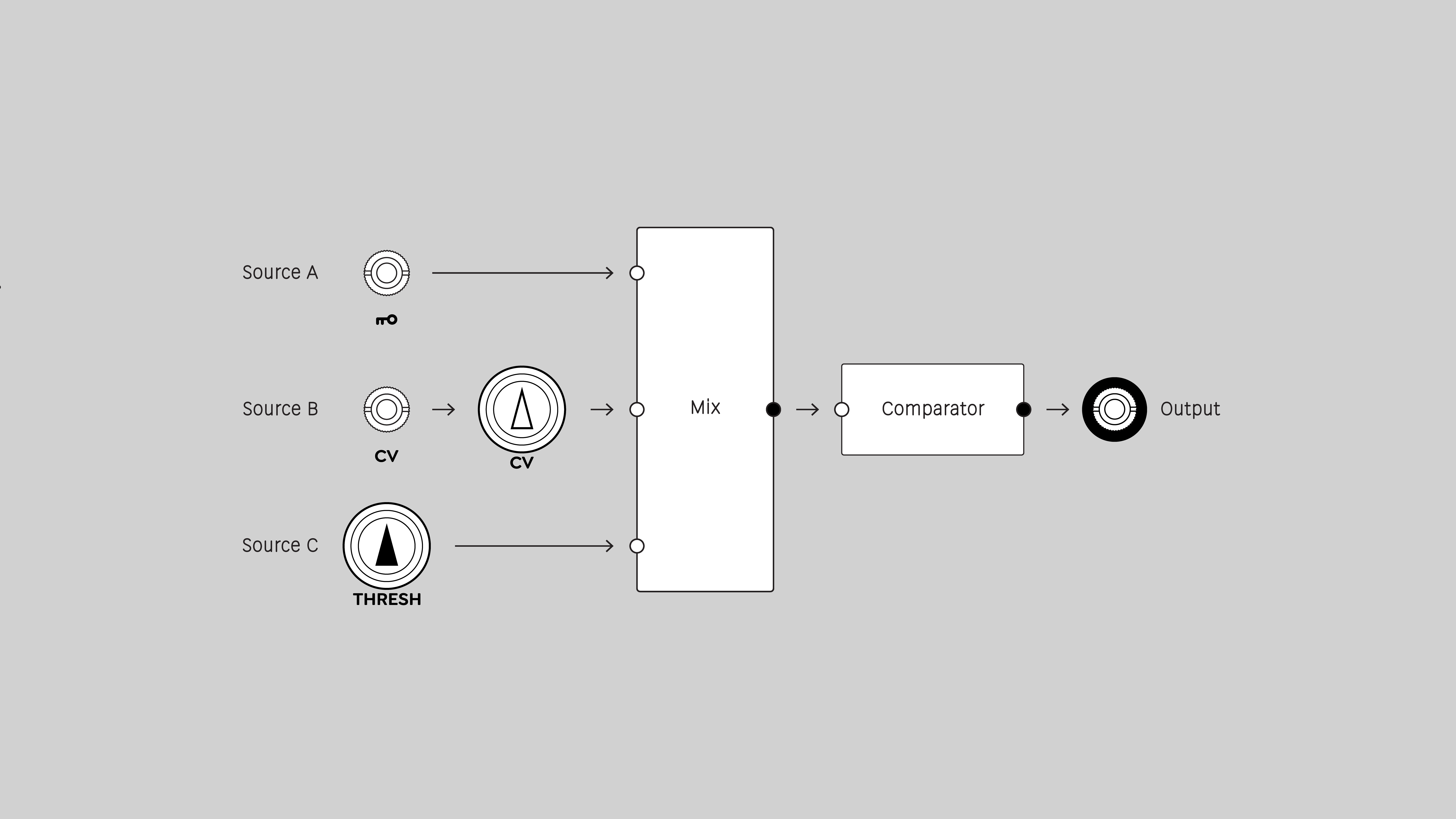
The output of the mixer goes into a lightning-fast comparator that slices the signal into two states, on or off. For video signals, this means different areas of the frame are rendered as matte values of zero or one volt. For low frequency signals, it means sudden transitions between black and white.
Keychain does not have a video sync input. Low frequency transitions can happen in the middle of a frame, causing visible frame tearing. To cause transitions to happen in the vertical interval between frames or fields, you'll need an audio sample and hold module and a trigger signal that goes high at the start of each frame.
Video Tutorial
3 Patches for Keychain
presented by Johnny Woods
Example Patches
For a hard key composite of two sources, send a Keychain output to the CV input of a crossfade module, such as Bridge or VH.S Crossfade.
Sending a Keychain output to PGO gives perfectly phase-aligned positive and negative alpha channels. This unlocks new achievements with mixers such as Proc and SMX3, turning them into hard keyers!
Since Keychain's inputs are internally normalled, it can generate three keys of different thresholds from the same source. One application, a three-level posterizer, uses the ABS outputs of DSG3 to create discrete, non-overlapping bands of values. Each band goes to a top row input of SMX3, giving independent control of RGB or YIQ colors.
Linear wipe
Hard-edged figures
Multiple thresholds
Shape variations
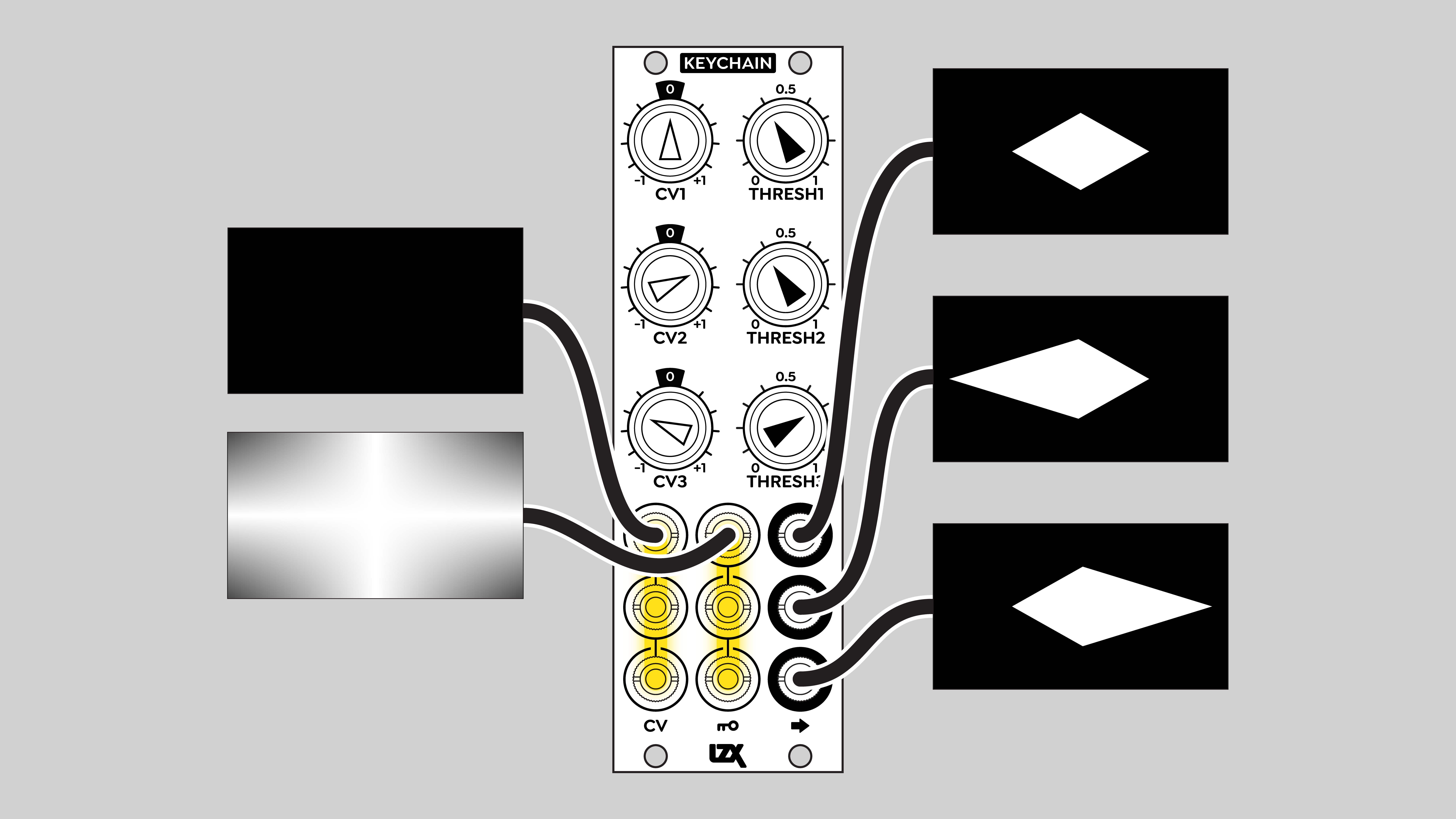
Animated figure / wipe
Installation
Requirements
- EuroRack enclosure
- 12V DC or EuroRack power supply
- 2.1mm DC barrel power cable or a EuroRack power cable (both options included)
- Four M2.5 x 6mm mounting screws, or screws provided or specified by the enclosure manufacturer
- #1 Phillips head screwdriver, or hand tool provided or specified by the enclosure manufacturer
Procedure
- Power off and disconnect the EuroRack enclosure's power supply and any attached DC adapters.
- Connect either the EuroRack Power Cable or the DC Barrel Power Cable to the module. Do not connect both Eurorack and DC Barrel power.
- Ensure that no mounting screws are in any holes in the area where you wish to mount the module.
- Carefully test fit the module with its attached power cable in the open space in the EuroRack enclosure. If it is obstructed by the enclosure or any internal assemblies, abort this procedure.
- Connect the disconnected end of the power cable to the power supply.
- Mount the module to the EuroRack rails using all mounting holes.
- Store the unused cable along with the product box in a safe location.
- Power on the EuroRack enclosure and start patching.
Full Specifications
| Connectors | Controls | |||||||||||||||||||||||||||||||||||
|---|---|---|---|---|---|---|---|---|---|---|---|---|---|---|---|---|---|---|---|---|---|---|---|---|---|---|---|---|---|---|---|---|---|---|---|---|
 |
|
|
Technical Data
| Manufacturer Part Number | 950056 |
| Mounting Width | 8 HP |
| Mounting Depth | 32 mm |
| Mounting Hole Count | 4 |
| Power Consumption | 12V @ 110 mA |
| Power Connectors | 16 pin EuroRack ribbon, 2.1mm DC barrel |
| Input Impedance | 1M ohms |
| Output Impedance | 75 ohms |
| Input Protection Range | +/-20V |
| Input Clipping Range | +/-2.5V |
| Output Range | +/-2.5V |
| Included | DC barrel power cable, EuroRack power cable |
| EuroRack Power Cable Type | 16-pin |
| EuroRack Power Cable Length | 25 cm |
| DC Barrel Power Cable Length | 25 cm |
| RoHS Compliance | Manufactured with lead-free processes. |
| Video Sync | None |
Maintenance
Keep your module free of dust and debris by performing periodic cleaning. Spots may be cleaned from the frontpanel with a microfiber cloth and isopropyl alcohol or other electronics cleaner.
Hardware Revisions
The hardware revision code is printed on the circuit board visible from the rear of the module.