TBC2
Overview
TBC2 is the most flexible, cost-effective, and space-efficient tool for bringing multiple video sources into a modular synth.
It's not an exaggeration to say that TBC2 compresses a sizable rack of conventional video equipment into a tiny space of only 16 HP. To achieve the capabilities of TBC2, a rig or studio setup would need the following:
- Sync generator
- Two full-frame time base correctors
- Two processing amplifiers
- Pattern generator
- Matrix router
- Crossfading mixer with two output busses
- Random access media player
Most of that gear would require genlock inputs for synchronizing to external clock reference. And such a system would still require two Eurorack decoders to convert conventional video to the LZX 1 volt patchable standard. All told, TBC2 replaces thousands of dollars of equipment that would be bulky, heavy, and power-hungry. TBC2 elegantly solves all of those problems, bringing half a studio of video gear directly into the modular synth.
Send SD or HD video into TBC2 in component, composite, or S-Video formats. TBC2's internal time base correctors synchronize the incoming video to the sync reference of the modular system. Each of the two TBC2 Encoder channels outputs RGB video and luminance in the LZX 0 to +1 volt patchable modular standard.
TBC2 can synchronize and decode two simultaneous channels of "wild" video. This eliminates the need for genlocked cameras or external media players. Sync can be entirely local to the modular system: it doesn't necessarily need to send or receive sync from anything else.
TBC2 provides sync I/O flexibility with inputs and outputs on the front panel and on the back of the module. This enables a wider range of system integration options, such as installing TBC2 in a different enclosure than the global sync generator.
Bonus features of TBC2 include still image and looping image sequence playback, crossfading between image sources, and internally generated horizontal and vertical video ramps.
Features:
- Decode and synchronize two SD or HD video input sources
- Component, Composite, and S-Video inputs
- Encode RGB and luminance to LZX 1v patchable outputs
- Support any conventional resolution and frame rate, up to 1080p30
- Optionally support VGA / VESA / SCART with 10HP expander, up to 1024x768p60
- Genlock and generate SD / HD sync via front and rear RCA jacks
- Display images and play looping sequences from MicroSD card
- Generate horizontal and vertical ramps
- Color correct each SD input: Hue, Saturation, Contrast, Brightness
- Automatically scale incoming video to fit the current format
- Crossfade between Decoder inputs, ramps, or Media Player
- Remotely control parameters via MIDI
Legacy
TBC2 is the second generation time base corrector from LZX. It's far more advanced than its Visionary series predecessor, the Color Time Base Corrector. TBC2 mk 1 was part of the Orion series, introducing dual TBCs, high definition, component inputs, ramps, media player, front and rear RCA sync, and many other features. TBC2 mk 2 has an updated Gen3 panel design inspired by camera control units and similar broadcast gear from the 90's. It was also among the first modules to feature 75 ohm output impedence, for crisper detail in HD.
Key Specifications
| Parameter | Value |
|---|---|
| Mounting Width | 16 HP |
| Power Consumption | 12V @ 600 mA |
| Power Connectors | 16 pin EuroRack ribbon, 2.1mm DC barrel |
| Included | DC barrel power cable, EuroRack power cable |
| Video Sync | Front and rear RCA in and out |
System Integration Advice
A decoder is necessary for getting external video into a video synth. TBC2 is by far the most advanced option ever available as a Eurorack module, because it's not just a decoder, it's a dual time base corrector. The frame synchronization and scaling capabilites of TBC2 solve a long list of problems related to video sync and formats. Without time base correctors, all video sources to the synthesizer would need to be in the same format and genlocked to the synth. Those are expensive requirements that complicate a rig or studio setup. TBC2 is the all-in one portable solution that is entirely contained within the modular synth enclosure.
Controls, Connectors & Indicators
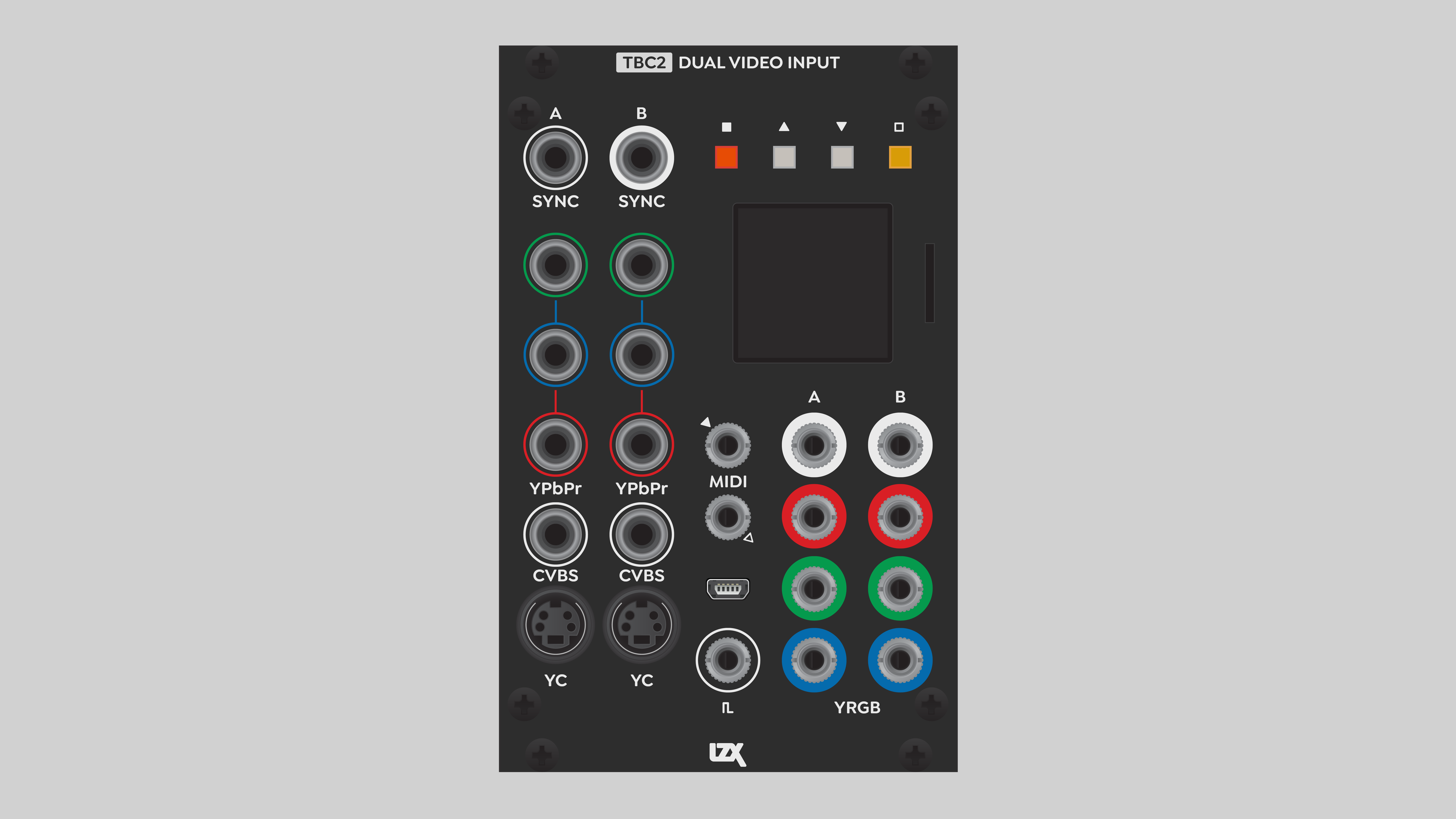
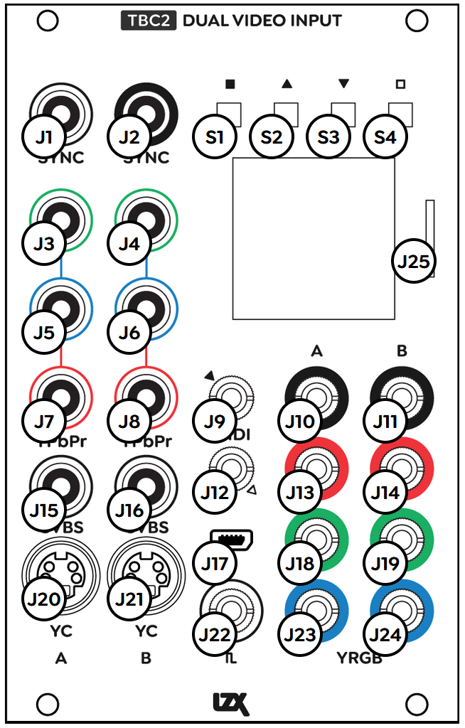
The TBC2 front panel essentially breaks down to inputs on the left, and outputs on the right.
Decoder Inputs
The two left-most columns of jacks are labeled A and B, corresponding to the two Decoder submodule inputs, described in the Decoder section below. For each Decoder you wish to use, patch a video source into the three RCA component inputs, an RCA composite input, or an S-Video input. Only one of those three inputs can be active at a time.
Front Panel Sync In and Out
At the top left are RCA jacks for video Sync Input and Sync Output. As explained in the Genlock section below, TBC2 is not designed as the ultimate source of sync in a modular system. It should receive sync from a dedicated sync generator module via the rear RCA connections. Alternatively, the TBC2 front panel sync input enables it to be installed in a different enclosure than the sync generator. More commonly, TBC2's front panel sync output is useful to send sync to another enclosure.
MIDI In and Out
In the center of the front panel are two mini jacks for MIDI In and MIDI Out. TBC2 is not capable of generating MIDI on its own, so the MIDI Out jack is actually a MIDI Through that buffers and echoes any MIDI messages received by the MIDI In jack.
The TBC2 MIDI jacks use the Type B TRS standard: a three-conductor tip-ring-sleeve (stereo) mini jack. The tip is the "source" conductor (+5v static), the ring is the "sink" or signal conductor, and the sleeve is the shield or ground.
The official MIDI standard is Type A, but this was adopted long after hardware manufacturers started using mini jacks. If you wish to interface TBC2 MIDI with other Eurorack modules, consult their hardware documentation. You may need an adapter. For example, Expert Sleepers modules use a tip-ring (mono) jack, called Type C. The shield conductor is omitted because over short patch cable runs there is no practical need for shielding from radio frequency interference.
TBC2 accepts MIDI Continuous Controller messages to remotely control the Encoder crossfader and SD color correction parameters listed in the MIDI Implementation section below.
Micro-USB
Directly below the MIDI jacks is a Micro-USB port. The current firmware does not provide any user functions for the USB port, it is solely for manufacturer development and testing.
Trigger In
At the bottom center of the front panel is a Trigger In mini-jack. This is not yet implemented.
1v Video Outputs
On the right side of the front panel are eight jacks for 0 to +1v patchable video outputs: four for each of the A and B Encoder submodules, described below.
The bottom pair of three video output jacks are color-coded to Red, Green and Blue, corresponding to the RGB color components of each Encoder channel. But the individual RGB jacks can also be assigned to internally-generated horizontal and vertical ramps, described in the Ramp Generator section below.
The top video output jacks are dedicated to luminance signals, also known as Y. The RGB components of the Decoder or Media submodules are summed. However, the RGB components do not contribute to luminance in equal amounts. RGB components are weighted according to the formula set by the CCIR-601 video standard. This unequal weighting accounts for the human perception of brightness as a function of hue. Green looks brighter than red, red looks brighter than blue. The result of the RGB summing formula is that a black and white luminance image appears to have the same approximate value tones as a full color image.
Button Switches and Display Screen
At the top right of the front panel is a row of four buttons. These are momentary switches enabling the artist to navigate through menu pages and choose parameter options from the OLED display screen.
The left-most, red button will Cancel the current operation. The middle, gray buttons, Up and Down, navigate through menu pages and parameters. The right-most, yellow button will Confirm the current choice, executing the change to a parameter value or option.
Operation
The TBC2 menu system is hierarchical. Menu pages contain menu items, or parameters. Parameters contain listed values or options.
Navigation and parameter control is accomplished via the four button switches at the top of the module. The general process is as follows:
- Press the gray Up and Down buttons to navigate to a menu page.
- To access the parameters within the current menu page, press the yellow Confirm button.
- Press the gray Up and Down buttons to navigate within the menu page. The current parameter is highlighted.
- To access the values or options for the current parameter, press the yellow Confirm button.
- Use the gray Up and Down buttons to choose the desired value or option for the current parameter.
- Press the yellow Confirm button to execute the chosen value or option for the current parameter.
- To exit the current parameter, press the red Cancel button.
- To exit parameter editing, and return to navigating menu pages, press the red Cancel button.
Firmware Submodules
TBC2 firmware consists of several functional processing blocks that the artist can configure to suit their needs. These processing blocks are collectively known as Submodules. Here, this term doesn't refer to a front panel scheme of exposing functions as dedicated sets of controls and I/O. TBC2 firmware submodules are high-level algorithms that do all of the work behind the scenes, configured via the TBC2 screen and buttons.
Decoder
TBC2 has two input Decoder submodules. Each supports the following standards for color, resolution, and frame rate:
| Supported input color formats |
|---|
| YPbBr component |
| RGsB component (sync on green) |
| Composite (CVBS) |
| S-Video (Y/C) |
| Supported input standards |
|---|
| NTSC 486i59 |
| PAL 576i50 |
| 480p |
| 576p |
| 720p50 |
| 720p59 |
| 720p60 |
| 1080i50 |
| 1080i59 |
| 1080i60 |
| 1080p23 |
| 1080p24 |
| 1080p25 |
| 1080p29 |
| 1080p30 |
| 640x480p60 |
| 800x600p60 |
| 1024x768p60 |
The input signal sent to the Decoder does not strictly need to match the output standard set by the Genlock submodule. TBC2 will automatically scale the image to the output format. As should be expected, the most reliable results come by matching the standards of the source video and Genlock submodule.
If the input and output frame rates don't match, TBC2 will need to drop or add frames.
Current firmware does not support deinterlacing. When converting interlaced to progressive, TBC2 will only use the first field. Scanlines are doubled, and the second field is discarded.
Genlock
TBC2 has one Genlock submodule. This module controls the timing of the output Encoders. It is a full-featured, genlockable sync generator with front and rear sync inputs and outputs.
Although it is possible to use TBC2 as the source of all sync inside the modular system, that is not its intended use. Configuring a system with TBC2 as the global clock is not recommended due to potential stability issues. The source of all sync in the system should be a module designed for that purpose, such as ESG3. For systems without a sync distribution amplifier, the optimal sync chain is:
When sync is looped through modules in series, the best practice is to route sync to ramp generators such as Angles or DSG3 directly after TBC2, and before everything else. Serial sync connections introduce propagation delays, causing images to shift slightly to the right. Propagation delay should be minimized for ramp generators in particular, because they define horizontal and vertical coordinates for pattern generation. Therefore, ramp generators should be placed early in the sync chain.
Sync issues such as propagation delay are eliminated by a sync distribution amplifier. Bus 168 is a purpose-designed sync and power distribution bus. It's included with Vessel 168, and available as a DIY kit. The sync routing for a system with a sync DA is:
| Supported output standards |
|---|
| NTSC 486i59 |
| PAL 576i50 |
| 480p29 |
| 576p25 |
| 720p50 |
| 720p59 |
| 720p60 |
| 1080i50 |
| 1080i59 |
| 1080i60 |
| 1080p23 |
| 1080p24 |
| 1080p25 |
| 1080p29 |
| 1080p30 |
Encoder
TBC2 has two output Encoder submodules. Each drives a set of four LZX modular video outputs, simultaneously providing Red, Green, Blue components and a grayscale Luminance signal. The Encoder video standard follows the setting of the Genlock submodule.
The source of each encoder is a crossfader. Each of the A or B inputs to a particular crossfader can be chosen from the following sources:
- Decoder A
- Decoder B
- Ramp Generator
- Media Player
Ramp Generator
TBC2 has one Ramp Generator submodule. Its output video standard follows the Genlock submodule.
The Ramp Generator uses a slow software renderer designed to generate gradients and other patterns. Currently, only horizontal and vertical ramps are implemented in the renderer.
TBC2 renders ramps when the module boots up, or when any settings affecting the ramps change, such as Genlock format.
Each Red, Green, or Blue Encoder output can be assigned to a horizontal or vertical ramp. This means that only one triplet of Encoder outputs is needed for a pair of complementary ramps. The other Encoder can output a Decoder or Media Player.
Crosstalk between color outputs is possible. This may be an issue if, for example, the ramps are used to build a raster for XY vector graphics. Signal bleed may result in distortion of raster geometry. Crosstalk is avoided by using the Red and Blue outputs only, and assigning the Green output to nothing.
Media Player
TBC2 has one Media submodule. It loads still images from a MicroSD card inserted into the front panel socket.
To minimize risk of data loss, always eject or insert a MicroSD card only when TBC2 is powered off. Keep remote backups of any data on the MicroSD card.
Images can be displayed as stills, or played back at the current frame rate as a motion picture sequence. See the Image Sequences section below.
Media Player output video standard follows the Genlock Module.
microSD Card Compatibility
TBC2 is compatible with some, but not all, microSD cards. We have tested the following specific brands and models, and verified them to be hassle-free.
| Brand/Series | Size | SKU |
|---|---|---|
| SanDisk | 8 GB | SDSDQAB-008G |
| SanDisk | 16 GB | SDSDQAB-016G |
To avoid counterfeit MicroSD cards, always purchase from a trusted vendor. We recommend Mouser and DigiKey.
Disk Format & Folder Structure
TBC2 requires the MicroSD to be formatted using the FAT32 file system with default sector size.
The Media submodule requires a very specific directory structure.
- The MicroSD card must have a top level folder named
media. - The
mediafolder must contain subfolders that can be named whatever is desired. - Still image files must be placed within a subfolder of
media.
For example:
/media/folder/frame1.png
The Media submodule provides no method for navigating a directory tree, or hierarchical folder structure. Files placed in nested subfolders cannot be accessed.
File Preparation
The Media submodule supports the following image file formats:
- .PNG - lossless compressed
- .BMP - uncompressed
- .JPG - lossy compressed - may exhibit image artifacts
The Media submodule can read files with long filenames, but the firmware has no way to display them. To make it possible to read the entire filename on the display, stick to the antique DOS filename requirement of "eight dot three". The filename can be up to eight characters long, followed by a dot, then a filename extension of three characters.
For best image quality, image files should match the current video standard of the Genlock submodule. If not, the image will be scaled to fit the pixel height determined by the Genlock submodule.
| Video format | Pixel resolution (width x height) |
|---|---|
| Standard Definition (SD) NTSC | 720 x 486 |
| Standard Definition (SD) PAL | 720 x 576 |
| Extended Definition (ED) | 1280 x 720 |
| Full High Definition (FHD) | 1920 x 1080 |
TBC2 supports broadcast NTSC and PAL digital video formats. These formats are slightly anamorphic, making use of non-square pixels. For example, a file prepared for NTSC has a resolution of 720x486, according to the CCIR-601 standard from 1982. If we divide 720 by 486, the result is a ratio of 1:48:1, but the picture aspect ratio of NTSC is actually 1.33:1. This is happening because more pixels are sampled in the horizontal dimension than in the vertical dimension (scanlines). The pixels themselves are rectangular, slightly narrower than their height, with a pixel aspect ratio of 0.9.
Video editing and compositing programs automatically handle the display of non-square pixels, so that they look correct on computer monitors that only support square pixels. But image editors like Photoshop may require manually configuring display settings to approximate the effect of non-square pixels. Otherwise, if nonsquare pixels are displayed as square, NTSC images will look stretched horizontally, and PAL images will look stretched vertically.
Memory and Folder Size Constraints
TBC2 loads all of the images within a media subfolder into random access memory. Any images that don't fit into RAM can't be loaded. This limits the useful size of any particular media folder to available RAM. That's approximately 200 megabytes, uncompressed.
"Uncompressed" means the amount of RAM the images use after they are decompressed from file storage. For a compressed format such as .PNG or .JPG, the file size is less than the RAM usage. The important part for TBC2 is the RAM. The folder size won't tell you if the folder will fit in RAM. Even if you use the uncompressed .BMP file format, the folder size doesn't correspond to the memory usage. The Media submodule uses 32 bits per pixel, but the .BMP file only uses 24 bits per pixel -- it doesn't support transparency.
We need to know our limits: what's the maximum number of files that can fit in RAM? To figure that, we need the image resolution. An uncompressed image of a particular resolution always uses the same amount of RAM. Assuming that all files within a folder have the same resolution, we can calculate the maximum number of files that can be loaded into RAM with this formula:
1,600,000,000 is the number of bits in 200 megabytes. 32 is the number of bits per pixel.
Maximum file counts per standard video resolution are listed in the table below.
| Pixel resolution | Maximum number of images per folder |
|---|---|
| 720 x 486 (NTSC) | 143 |
| 720 x 576 (PAL) | 120 |
| 1280 x 720 (Extended Definition) | 54 |
| 1920 x 1080 (Full High Definition) | 24 |
Image Sequences
A media folder can be played back as a motion picture at the current frame rate of the Genlock submodule. To ensure proper playback order, follow these practices.
Sequential Filenames
With current TBC2 firmware, it's not a technical requirement to name files in an alphanumeric sequence. But it's standard practice in video and animation production, and it will save your sanity.
The best way to do this is with trailing numerals in the filename. For maximum compatibility with various systems, the file numbers should be padded with leading digits. For example:
- seqa_001.png
- seqa_002.png
- seqa_003.png
etc.
File Playback Order
The Media submodule plays back files in the order that they were saved on the MicroSD card. Not the alphanumeric order of filenames. Not the order in which they were originally created.
Currently, the most reliable method of ensuring correct sequential playback is to copy the files to the MicroSD card one at a time, in the desired playback order . This is very tedious, and ideally we could just copy the entire folder. But unfortunately, the host operating system may not copy the files in alphanumeric order.
Depending on the operating system, you may be able to trick the file browser into copying files in the needed order. On Windows, try this. Manually create an empty folder on the MicroSD card. Select the files you wish to copy in REVERSE order. Click the last file, hold SHIFT, then click the first file. Copy the selected files to the MicroSD card folder.
MIDI Implementation
MIDI receive channel is configurable through the menus.
Continuous Controller numbers are fixed to the following mapping:
| CC | Module | Parameter |
|---|---|---|
| 0 | Encoder A | Crossfade |
| 1 | Decoder A | SD Processor Hue |
| 2 | Decoder A | SD Processor Saturation |
| 3 | Decoder A | SD Processor Brightness |
| 4 | Decoder A | SD Processor Contrast |
| 16 | Encoder B | Crossfade |
| 17 | Decoder B | SD Processor Hue |
| 18 | Decoder B | SD Processor Saturation |
| 19 | Decoder B | SD Processor Brightness |
| 20 | Decoder B | SD Processor Contrast |
Video Tutorials
3 Patches for TBC2
presented by Johnny Woods
How To Replace Your TBC2 Frontpanel
demonstrating updating the front panel from Orion to Gen3
Installation
Requirements
- EuroRack enclosure
- 12V DC or EuroRack power supply
- 2.1mm DC barrel power cable or a EuroRack power cable (both options included)
- Four M2.5 x 6mm mounting screws, or screws provided or specified by the enclosure manufacturer
- #1 Phillips head screwdriver, or hand tool provided or specified by the enclosure manufacturer
Procedure
- Power off and disconnect the EuroRack enclosure's power supply and any attached DC adapters.
- Connect either the EuroRack Power Cable or the DC Barrel Power Cable to the module. Do not connect both Eurorack and DC Barrel power.
- Ensure that no mounting screws are in any holes in the area where you wish to mount the module.
- Carefully test fit the module with its attached power cable in the open space in the EuroRack enclosure. If it is obstructed by the enclosure or any internal assemblies, abort this procedure.
- Connect the disconnected end of the power cable to the power supply.
- If a sync generator such as ESG3 is present in the same enclosure, connect the TBC2 rear sync input to the sync generator rear sync output. If the enclosure includes a sync distribution amplifier, connect the TBC2 rear sync input to one of the sync DA outputs.
- In the absence of a sync distribution amplifier within the enclosure, connect the TBC2 rear sync output to the rear sync input of the next module in the sync chain.
- Mount the module to the EuroRack rails using all mounting holes.
- Store the unused cable along with the product box in a safe location.
- Power on the EuroRack enclosure and start patching.
Full Specifications
| Connectors | Connectors and Controls | |||||||||||||||||||||||||||||||||||||||||||||||||||||||||||||||||
|---|---|---|---|---|---|---|---|---|---|---|---|---|---|---|---|---|---|---|---|---|---|---|---|---|---|---|---|---|---|---|---|---|---|---|---|---|---|---|---|---|---|---|---|---|---|---|---|---|---|---|---|---|---|---|---|---|---|---|---|---|---|---|---|---|---|---|
 |
|
|
Technical Data
| Parameter | Value |
|---|---|
| Manufacturer Part Number: Mk 1 (Orion) | 950046 |
| Manufacturer Part Number: Mk 2 (Gen 3) | 950058 |
| Mounting Width | 16 HP |
| Mounting Depth | 55 mm |
| Mounting Hole Count | 4 |
| Power Consumption | 12V @ 600 mA |
| Power Connectors | 16 pin EuroRack ribbon, 2.1mm DC barrel |
| Input Impedance | 1M ohms |
| Output Impedance | 75 ohms |
| Input Protection Range | +/-20V |
| Input Clipping Range | +/-2.5V |
| Output Range | +/-2.5V |
| Included | DC barrel power cable, EuroRack power cable |
| EuroRack Power Cable Type | 16-pin |
| EuroRack Power Cable Length | 25 cm |
| DC Barrel Power Cable Length | 25 cm |
| RoHS Compliance | Manufactured with lead-free processes |
| Video Sync | Front & rear RCA in & out |
Maintenance
Keep the module free of dust and debris by performing periodic cleaning. Spots may be cleaned from the front panel with a microfiber cloth and isopropyl alcohol or other electronics cleaner.
Hardware Revisions
The hardware revision code is printed on the circuit board visible from the rear of the module.
Troubleshooting
If the module powers up but the screen is blank, follow this procedure:
- Format a Micro SD card, sized 16 GB or smaller.
- Download the latest firmware package from the links in the Downloads section below and unzip the files.
- Find
BOOT.binand copy it to the MicroSD card. - Ensure that you have physical access to the back of the module. If necessary, power down TBC2 and remove it from the enclosure, keeping the module power cord connected.
- Power down TBC2 and insert the MicroSD card.
- Find the two buttons on the back edge of the module's circuit board. Hold down the top button (labeled Boot from SD on early units), power up the module, and wait for it to finish booting.
- On the System page, navigate to the Update Firmware parameter and press the Confirm button. Once complete, power cycle the module.
- If the issue persists, submit a service request.
Factory Reset
To reset TBC2 firmware to the version shipped from the factory:
- On the System page, navigate to the Reset Firmware parameter and press the Confirm button.
- Wait for firmware reset to complete, until the System Restart prompt appears.
- Press the Confirm button to reboot the module.
- Confirm that TBC2 boots to the factory installed version by checking the version number on the System page. If the wrong version is displayed, power cycle the module.
Firmware Update
To install a different version of the TBC2 firmware:
- Format a Micro SD card, sized 16 GB or smaller.
- Download the latest firmware package from the links in the Downloads section below and unzip the files.
- Find
BOOT.BINand copy it to the MicroSD card. - Power down TBC2 and insert the MicroSD card.
- Power up TBC2 and wait for it to finish booting.
- On the System page, navigate to the Update Firmware parameter and press the Confirm button.
- Wait for firmware update to complete, until the System Restart prompt appears.
- Press the Confirm button to reboot the module.
- Confirm that TBC2 boots to the correct version by checking the version number on the System page. If the wrong version is displayed, power cycle the module.
Downloads
TBC2 Firmware 1.0
Download ZIP
TBC2 Firmware 1.0.1
Download ZIP
TBC2-mk1 (Orion series) Firmware 1.0.2
Download ZIP
TBC2-mk2 (Gen3 series) Firmware 1.0.2
Download ZIP
TBC2 Firmware 1.0.3
Download ZIP
TBC2 Firmware 1.0.6
Download ZIP
TBC2 Firmware 1.0.7
Download ZIP
Firmware Changelog
1.0.7
Bug Fixes
- Fixed GUI slider behavior for Mk1 compatibility
- Fixed GUI labeling error in ramp generator
1.0.6
Bug Fixes
- Fixed decoder getting stuck in a scanning loop on certain inputs
- Fixed OLED preview scrolling during PAL-to-NTSC conversion
- Fixed HD component input sync glitch causing picture displacement
- Fixed encoder output not following source selection
- Fixed bouncing ball screensaver going off-screen
- Fixed various crashes and stability issues
New Features
- Added letterbox scaling for cross-format conversions
- Added confirmation prompts before firmware update/reset
- Added invert and triangle controls to ramp generator
- Shows error when SD card or BOOT.bin is missing during firmware update
Improvements
- Ramp phase control now goes from 0–360 degrees
- Renamed shutdown button to "Save & Restart"
- Decoder GUI adapts layout to input/output resolution