PGO
Overview
PGO is a multipurpose analog operator for adding and subtracting signals. It's designed to cover as much functional territory as possible in a compact and intuitive 4HP package.
PGO performs many basic processing steps such as:
- Amplify
- Attenuate
- Invert
- Add
- Subtract
- Average
- Bias (offset / level shift)
Key Specifications
| Mounting Width | 4 HP |
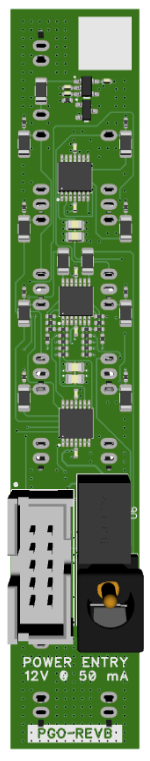
| Power Consumption | 12V @ 50 mA |
| Power Connectors | 10 pin EuroRack ribbon, 2.1mm DC barrel |
| Included | DC barrel power cable, EuroRack power cable, red panel, green panel, blue panel |
| Video Sync | None |
Front Panel Options
PGO ships with a black front panel installed. Red, green and blue panels are also included.
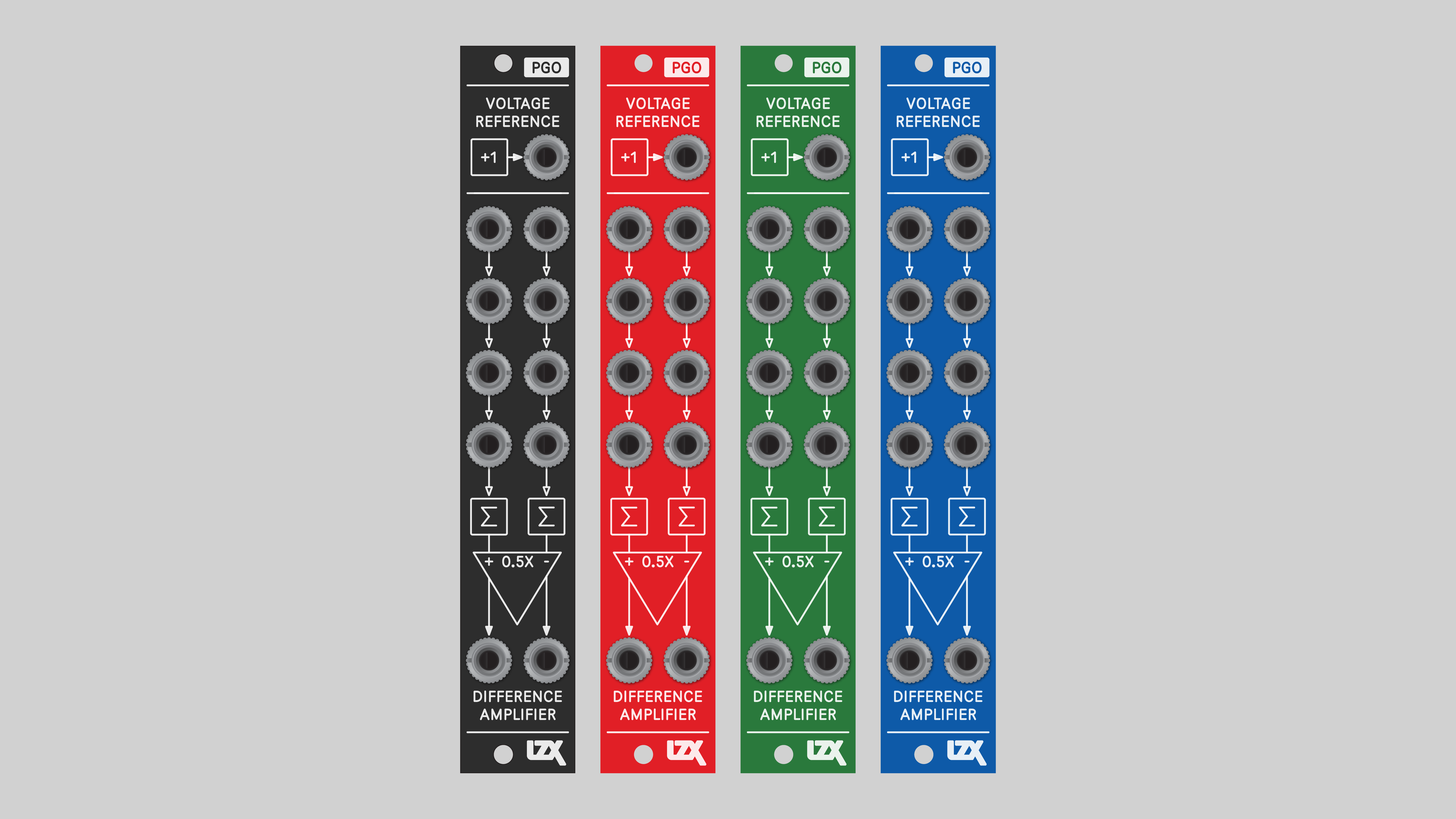
All front panels are printed on both sides, allowing a choice of top-to-bottom or bottom-to-top signal flow. This gives great flexibility in designing modular systems.
System Integration Advice
- Utility module for mixing and level shifting, covering cases where the patch needs just one simple operation.
- Expander to augment the functionality of other modules. Add more inputs. Process signals before or after any module. To expand modulation or signal input options, add PGO's next to your favorite high-level functions such as oscillators or shape generators.
- Building block for patching complex video synthesis functions. As low level analog computing blocks, several PGO's can be patched together to design a wide range of processing functions, including replicating functions from other modules. This level of flexibility comes at the expense of greater system size and more complex patches. Using both low-level and high-level modules is a great strategy for getting the most out of a system.
- The more, the merrier. More PGO's doesn't add possibilities, it multiplies them. PGO is a functional unit of an analog computer specialized for video. To operate as a traditional analog computer, a system requires multiple instances of summing and difference amplifiers. Bidirectional voltage conversion would require two PGO's. A triple color space function requires three. More complex vector functions require eight or more.
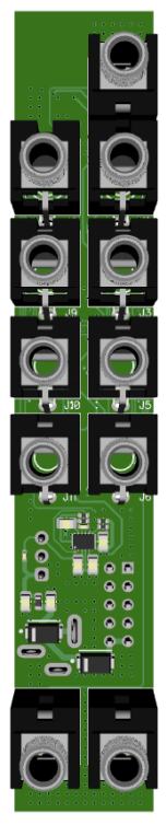
Connectors
The PGO design was informed by years of studying interfaces common to the building blocks of analog computers and video processing equipment.
Operation
PGO sits at a lower level of abstraction than more complex modules like video shape generators and video keyers. The synthesist is granted full access to the signal path, and the freedom to program a function in discrete steps.
PGO is a patch-programmable operator. Its overall function is determined by patch connections rather than switch positions or variable voltages. Connections to specific input and output jacks define operations at different mixing ratios and amounts of gain.
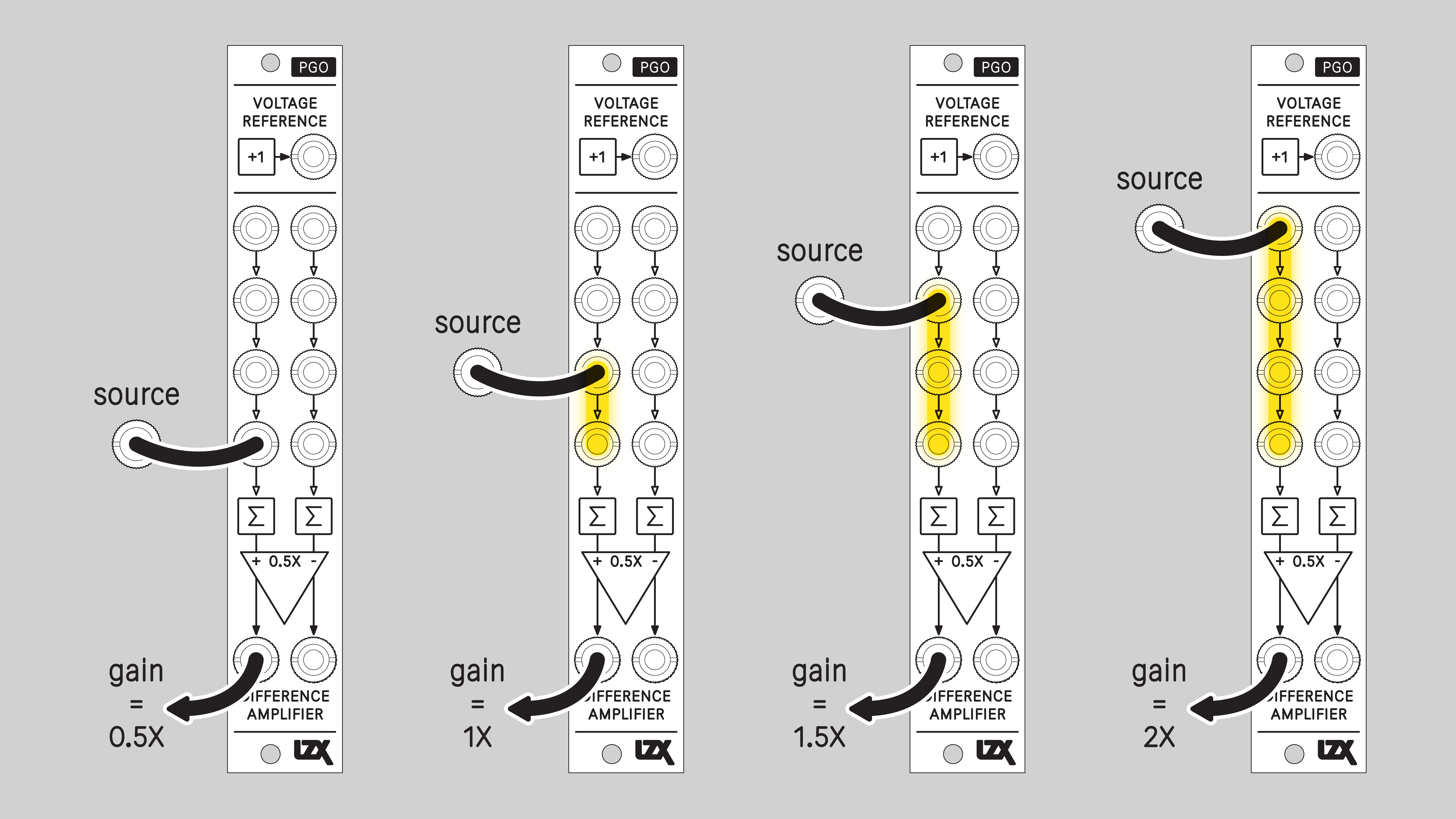
Understanding Cascading Input Jacks
PGO uses switched, or normalled, connections between some of its input jacks. With no cable inserted, a signal flows from one input jack to another. This connection is overridden when a cable is inserted. Normalled inputs are indicated on the front panel with arrows.

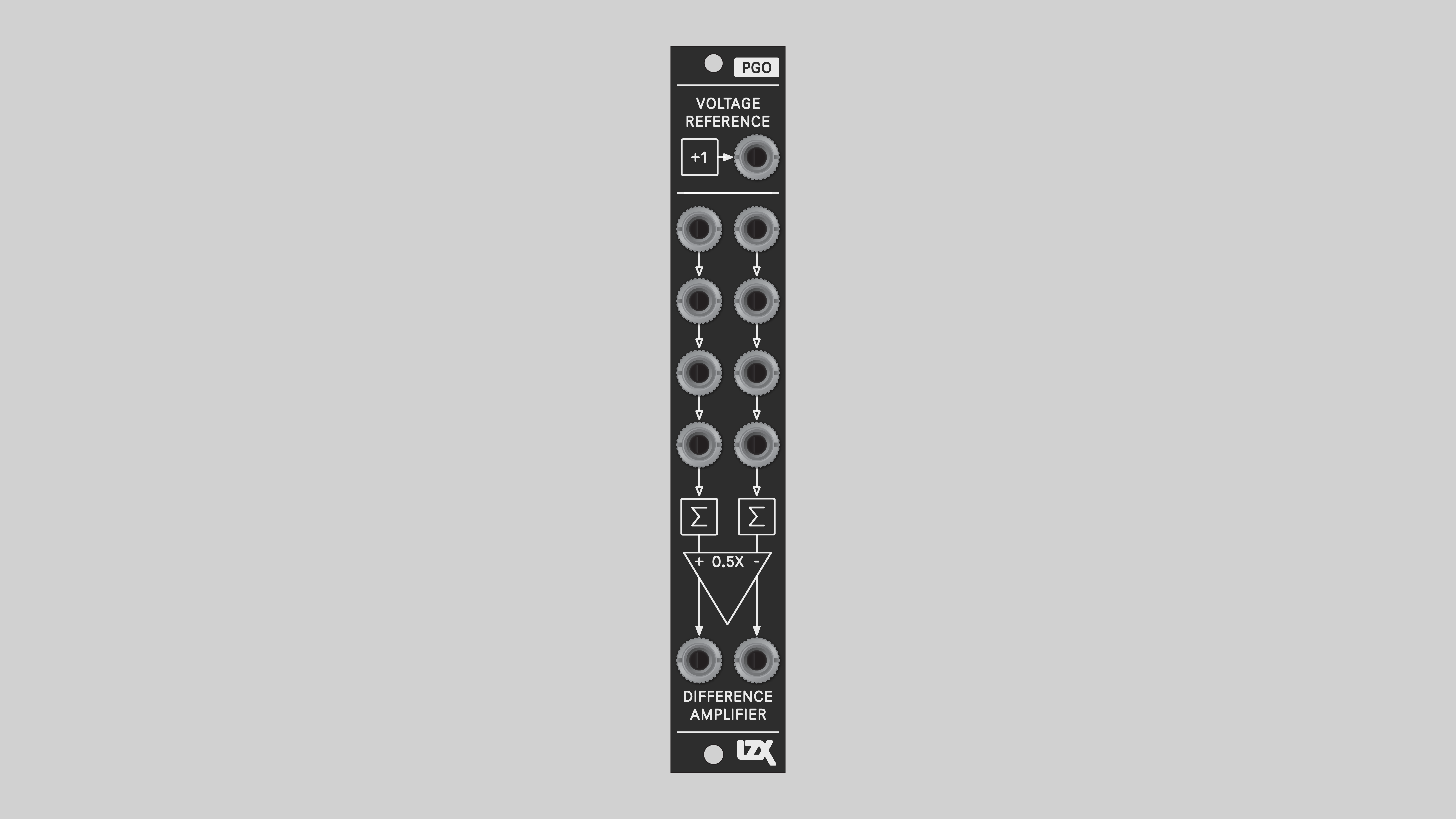
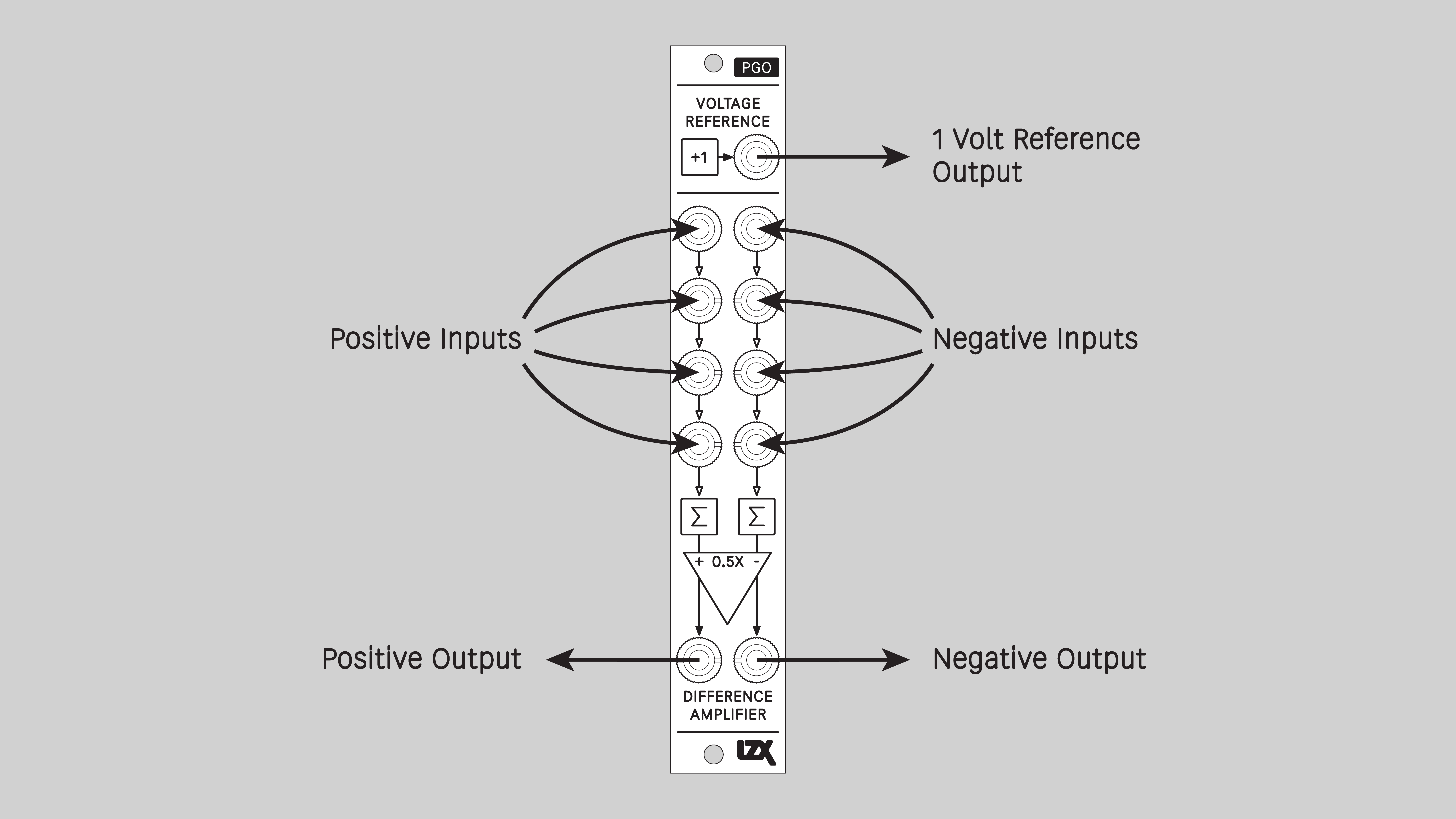
Difference Amplifier
A difference amplifier subtracts one voltage from another. It is similar to a differential amplifier, but is specifically optimized to subtract one voltage from another with accuracy. PGO's amplifier is fully differential, meaning that it has both positive and negative outputs.
In PGO's implementation, the positive input and negative input of the difference amplifier are each preceded by a four-input summing amplifier stage. This configuration allows the user to simultaneously add and subtract multiple signals. Due to the cascading input switches, the gain of each side of the difference amplifier may be programmed by which jacks are patched and which jacks are left open.
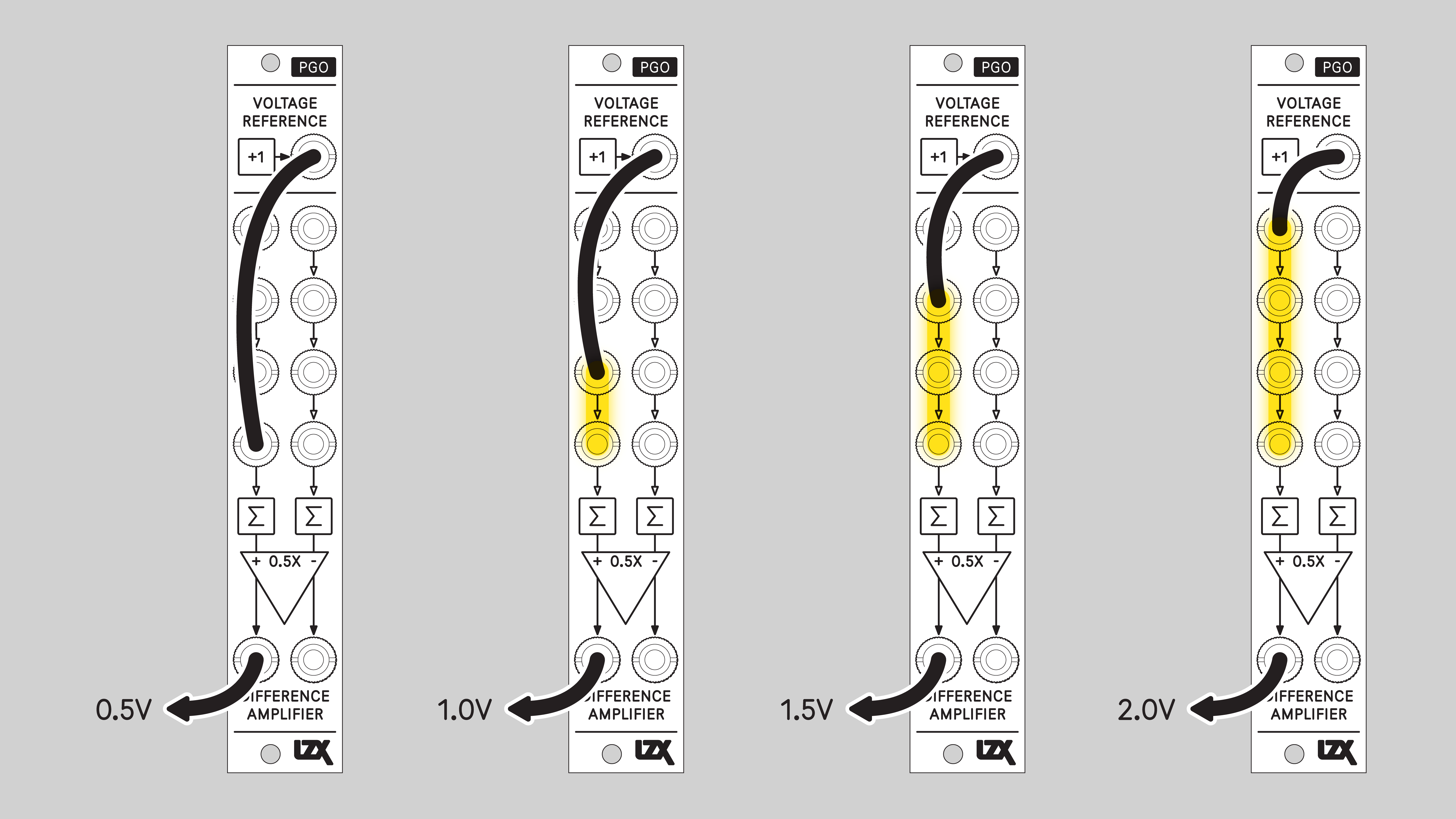
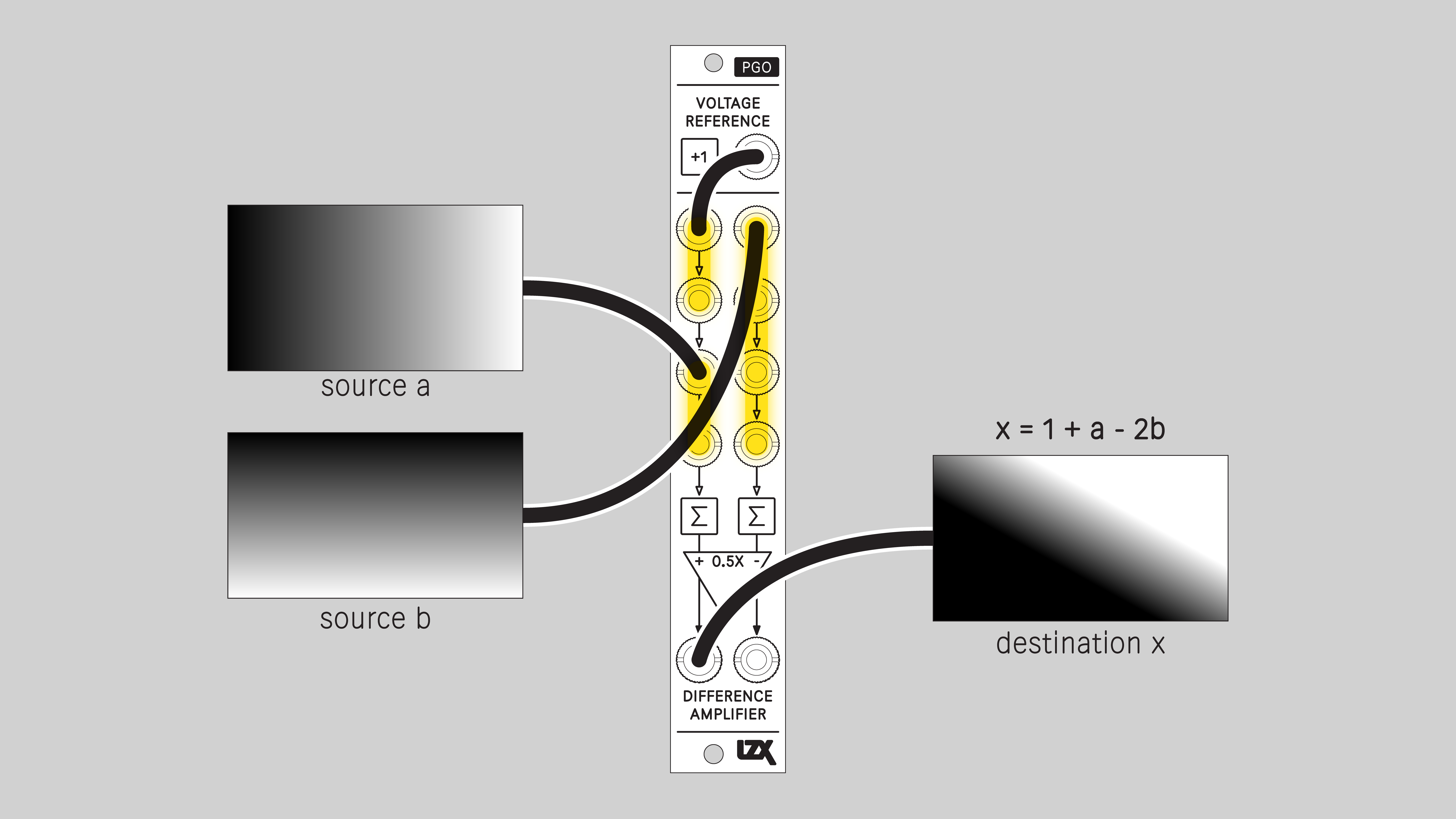
Voltage Reference
PGO provides a static voltage reference of 1V at its output jack. This level corresponds to a luminance value of white, or to the 100% brightness level of an RGB channel. This reference voltage may be patched anywhere in your system, or to the inputs on PGO.
Example Patches
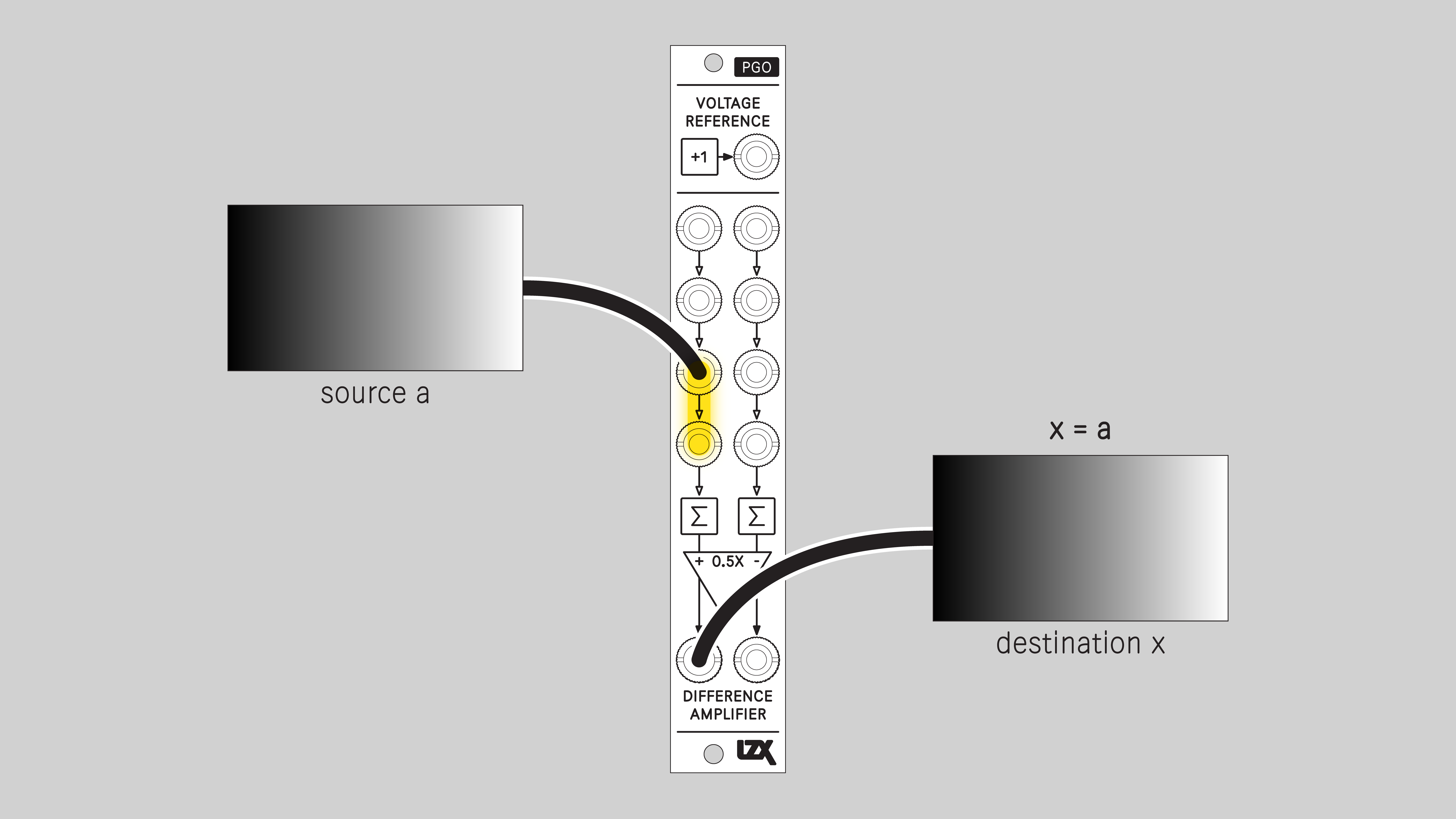
Buffer
Buffer the input signal with a unity gain of 1.0. Due to the module's propagation delay, it can be used to add slight delays in the video processing path, resulting in the picture shifting slightly to the right.
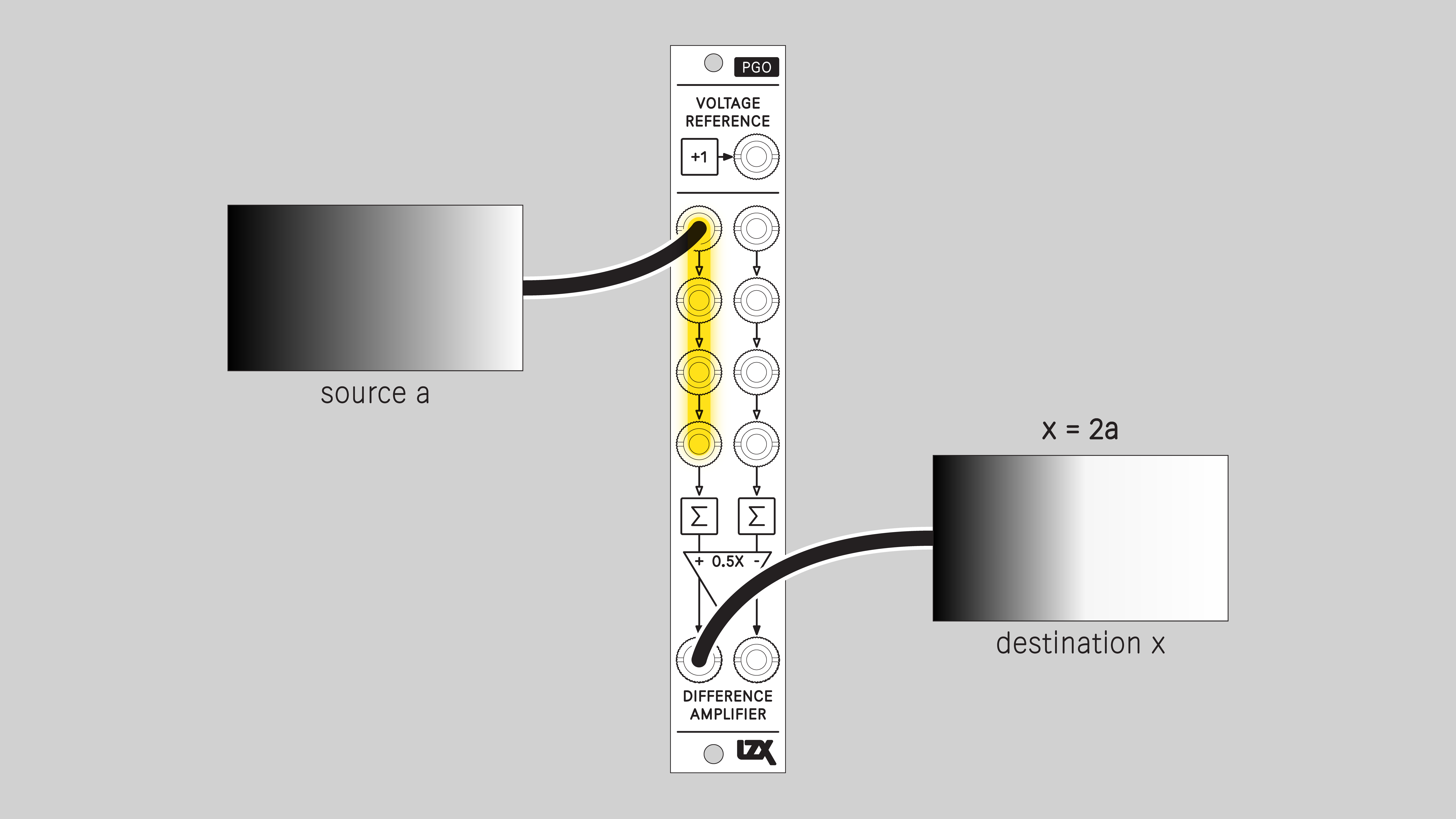
Amplifiy
Amplify the input signal with a gain of 2.
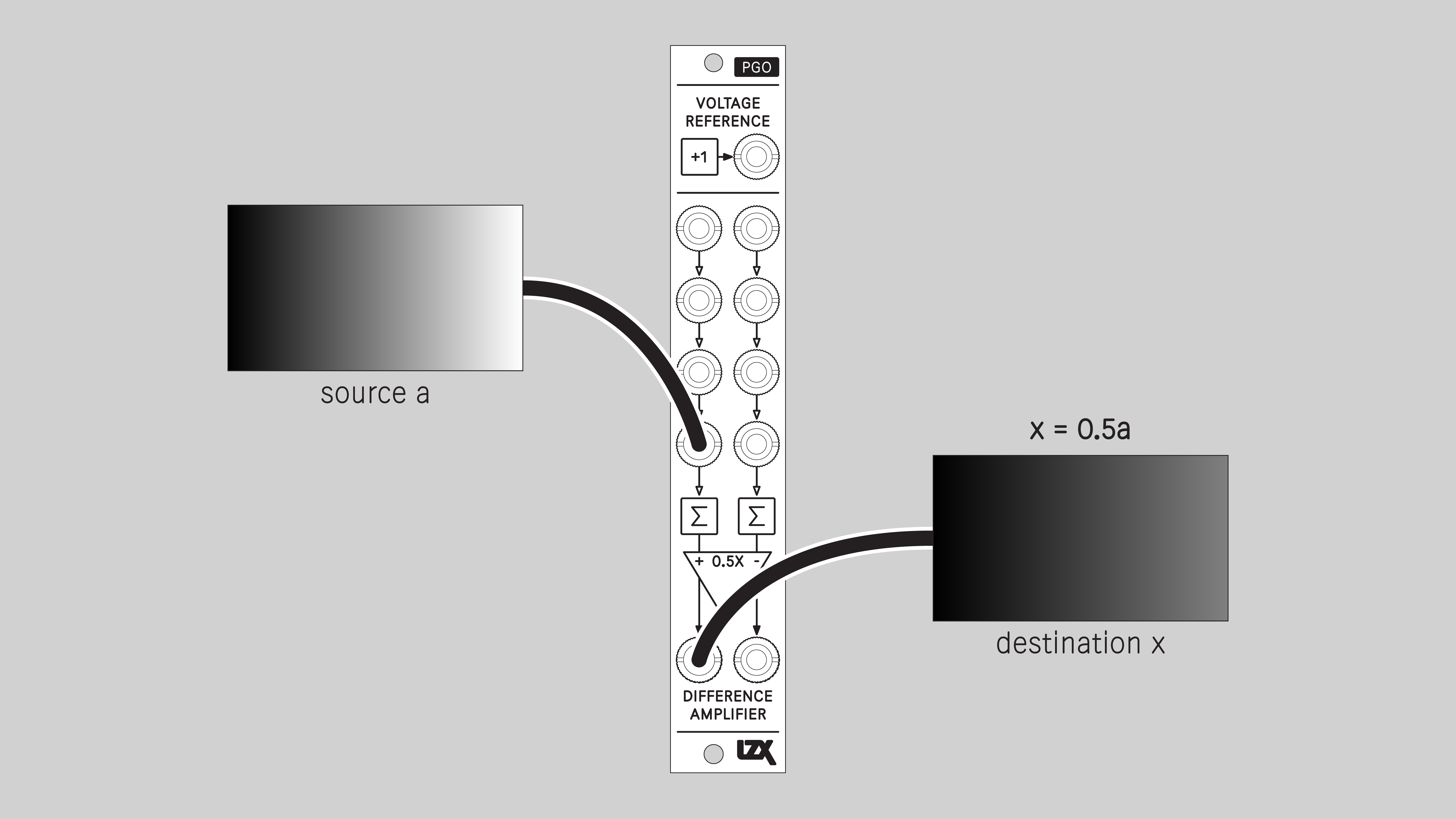
Attenuate
Attenuate the input signal with a gain of 0.5.
Invert
Invert the arithmetic sign of the input signal. Positive voltages are converted to negative voltages, or vice versa.
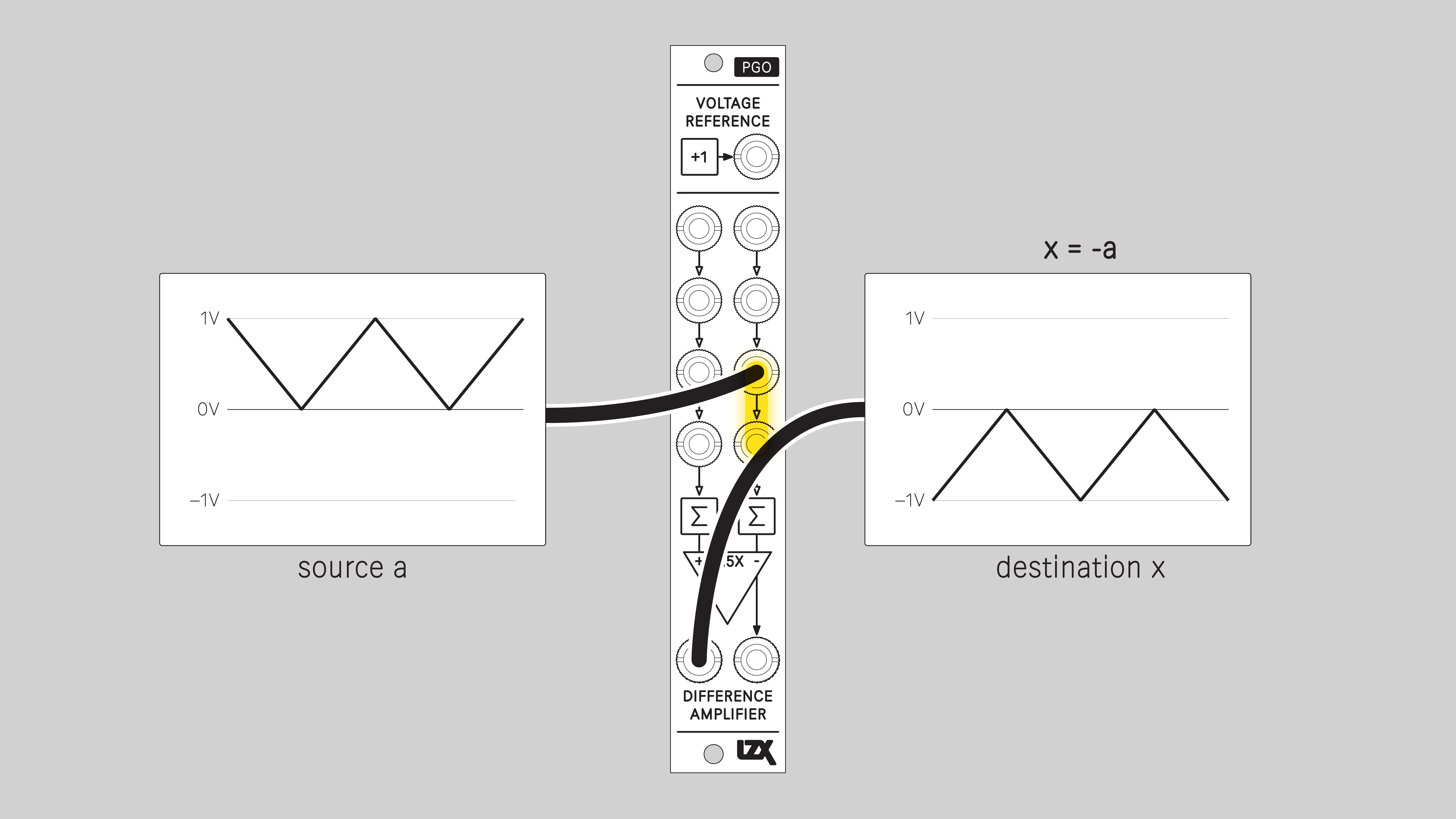
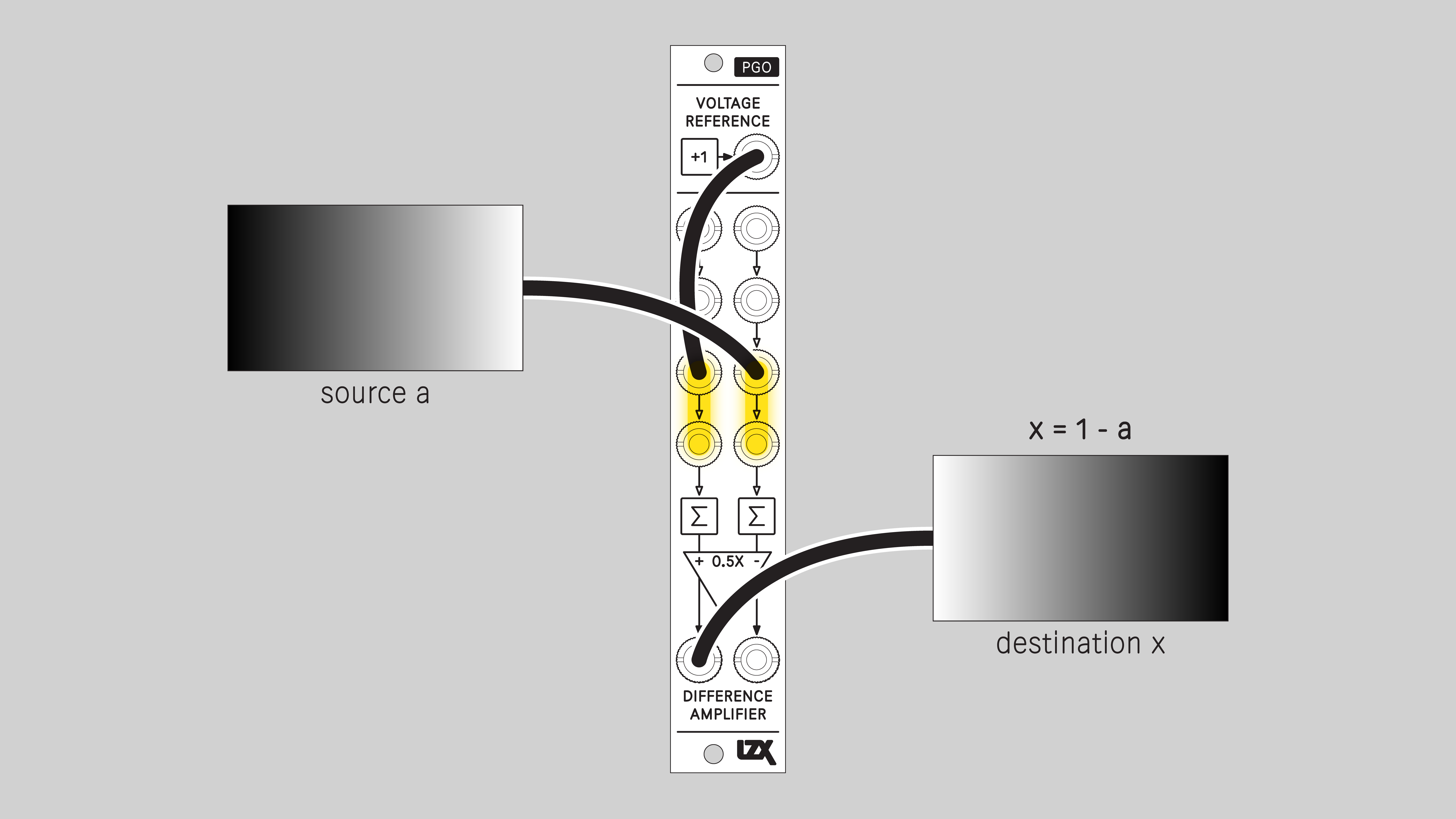
Negative
Convert a unipolar signal to negative by subtracting it from 1V. Useful for inverting keys, logic and RGB channels. An input signal ranging from zero to one results in an inverted output ranging from one to zero.
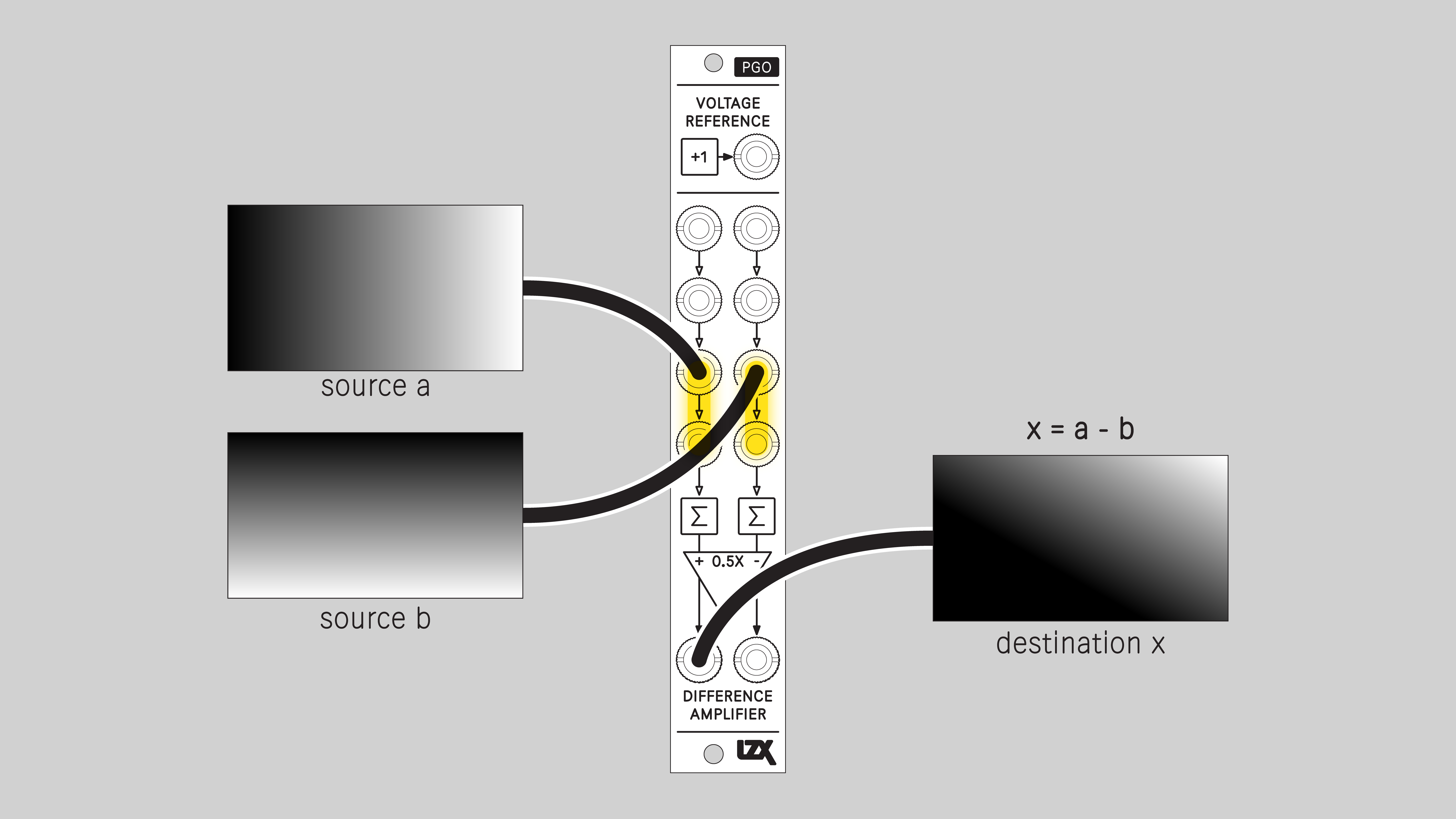
Subtract
Subtract one input from another.
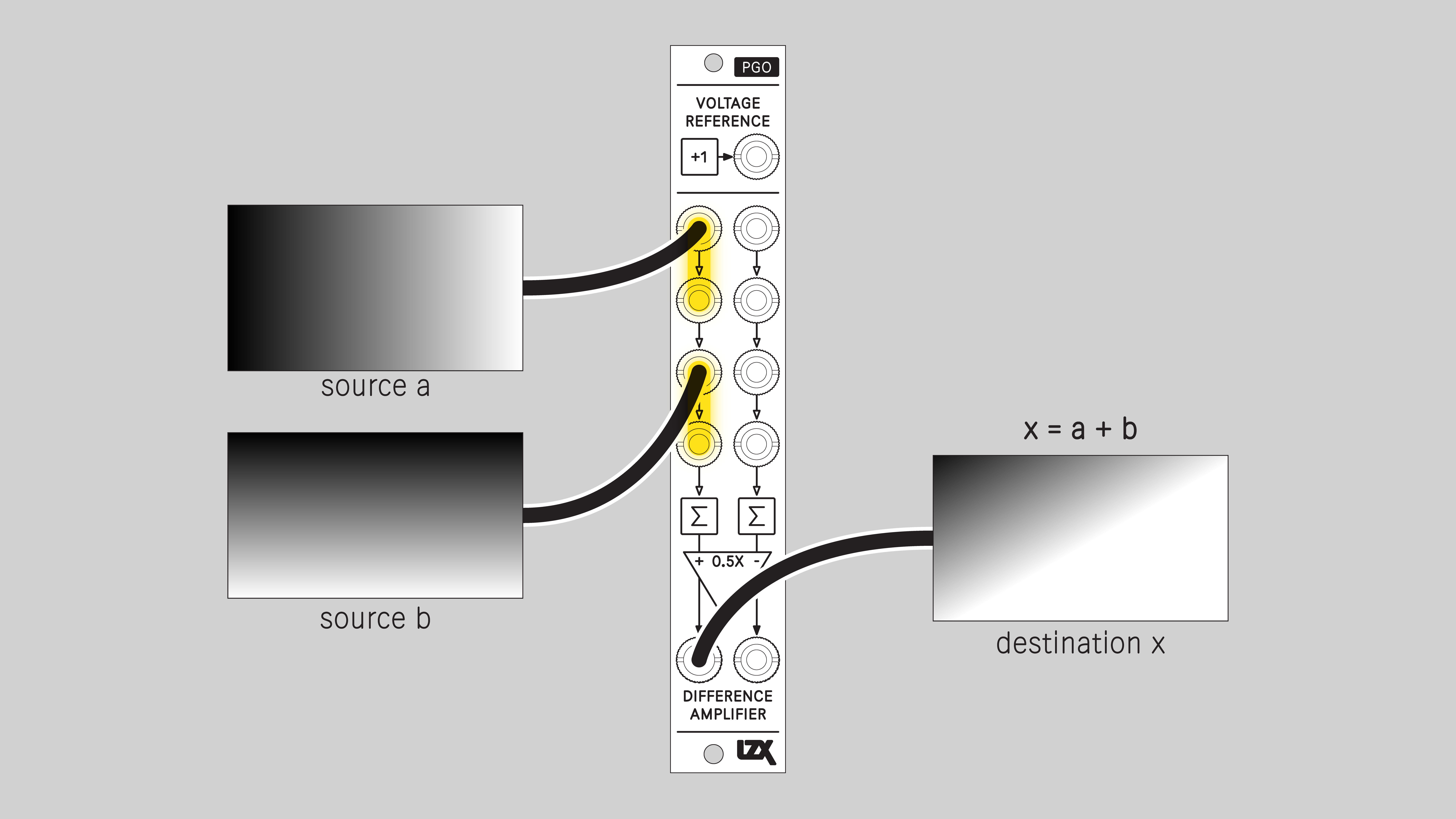
Add
Calculate the sum of two input signals.
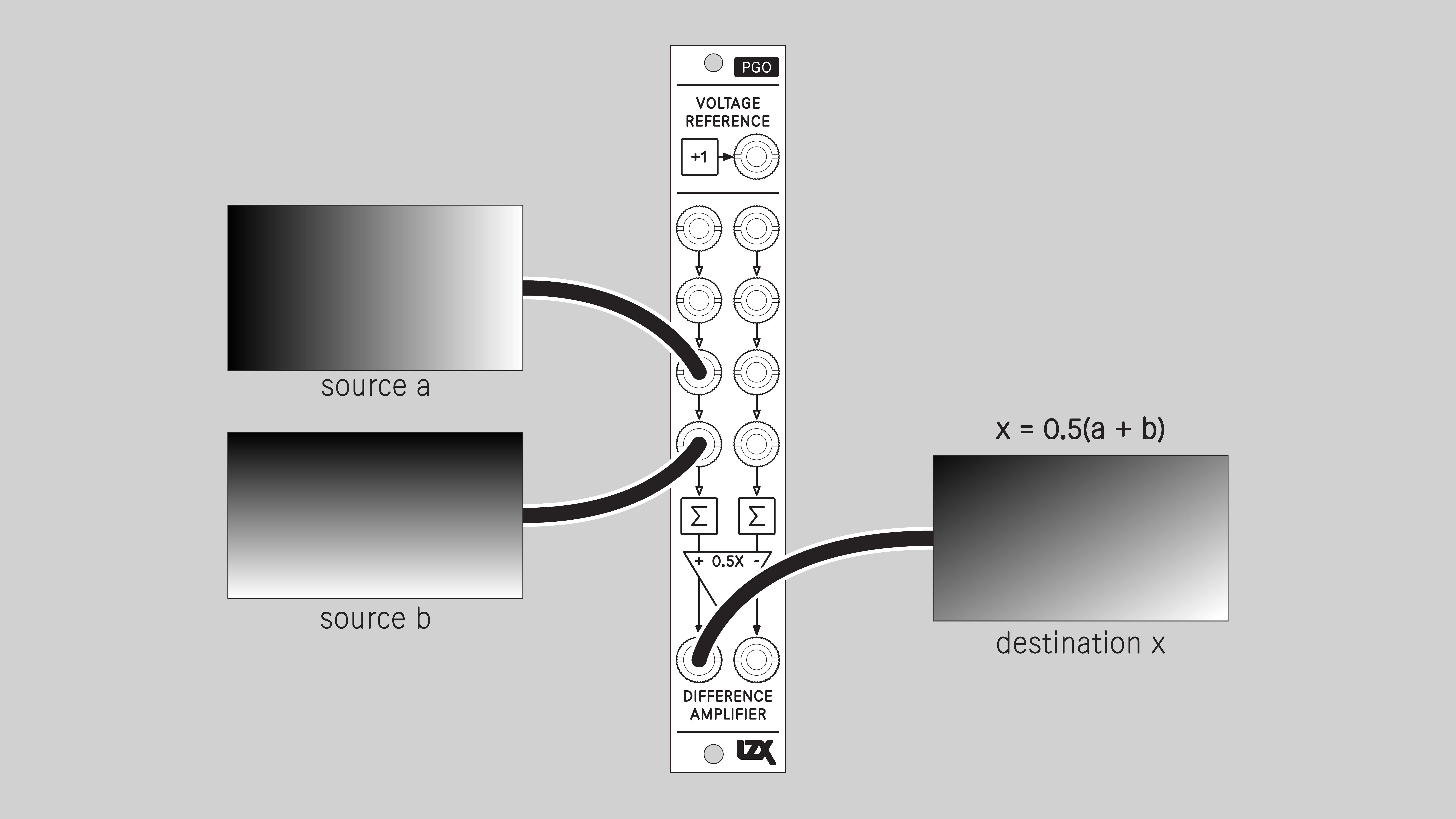
Average
Calculate the average of two input signals.
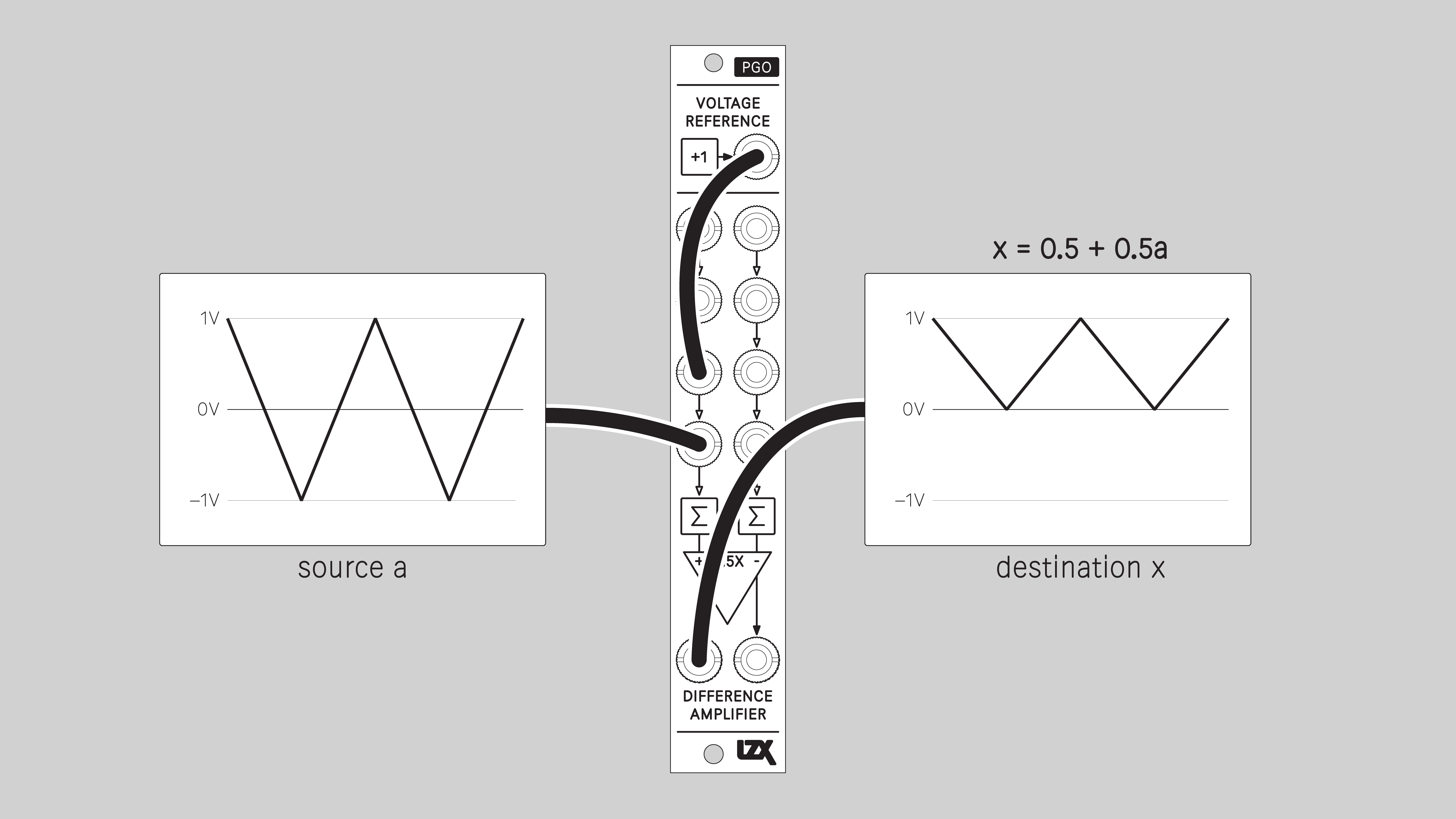
Unipolar Modulation
Subtract a modulator from a primary signal, where both are unipolar, from zero to +1V. The primary signal source a passes unmodified when the modulating signal source b is at its midpoint of 0.5V. As a ramp shifter, source a is the input ramp, and source b is the positioning control voltage. As a brightness processor, source a is a unipolar color channel such as luma, red, green, or blue, and source b is the brightness adjustment.
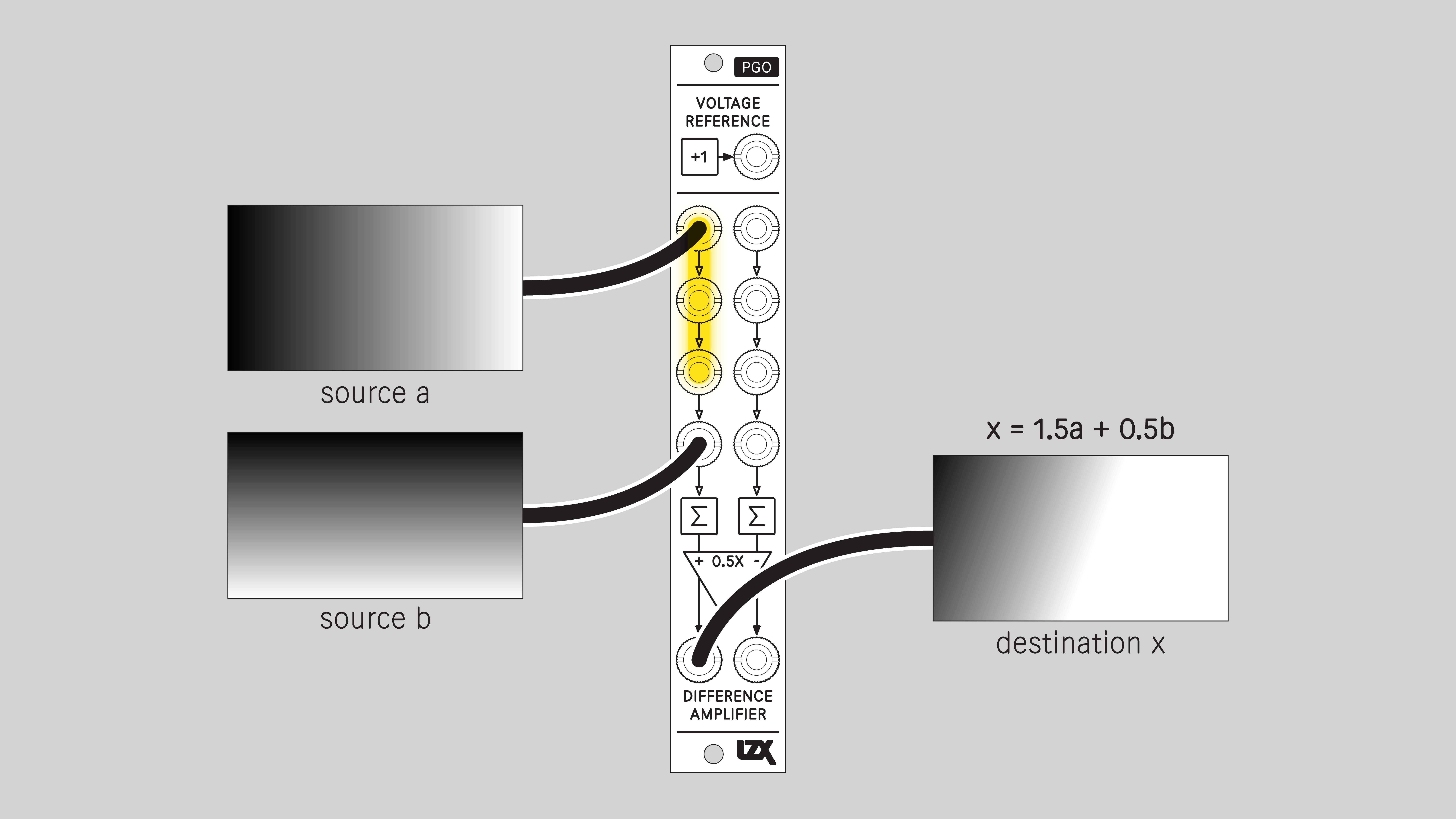
Weighted Mixer
Calculate a 3:1 weighted sum of two inputs, with 3 parts of source a for every 1 part of source b.
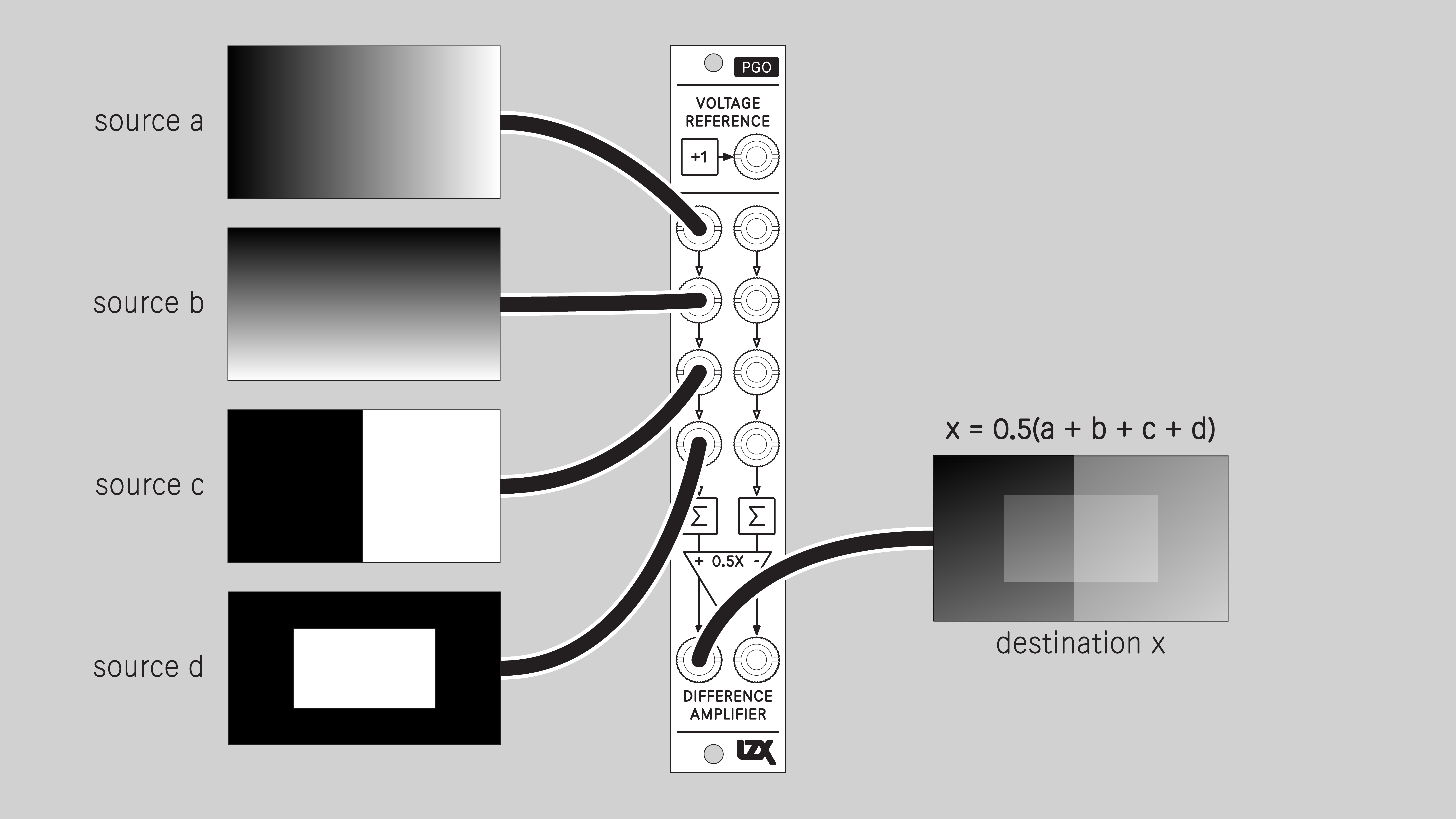
Compressed Mixer
Calculate the sum of four input signals and attenuate the mix to a value of one half. This is a common scenario to prevent clipping when mixing more than two input signals.
Bipolar to Unipolar
Convert a +/-1V bipolar signal to the 0-1V unipolar range.
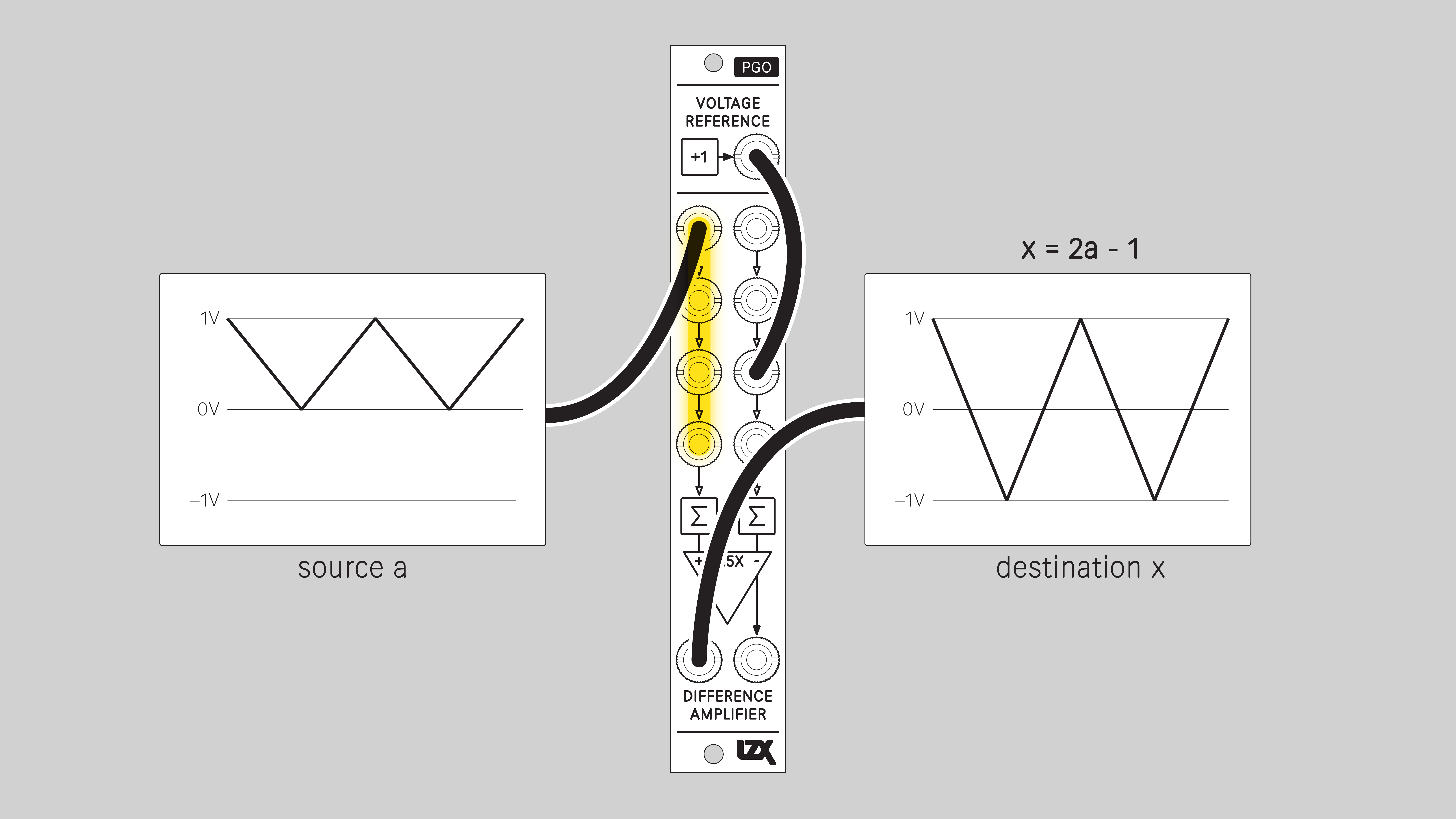
Unipolar to Bipolar
Convert a 0-1V unipolar signal to the +/-1V bipolar range.
Installation
Requirements
- EuroRack enclosure
- 12V DC or EuroRack power supply
- 2.1 mm DC barrel power cable or EuroRack power cable (both options included)
- Eurorack power for PGO requires a 16-pin to 10-pin ribbon cable
- Two M2.5 x 6mm mounting screws, or screws provided or specified by the enclosure manufacturer
- #1 Phillips head screwdriver, or hand tool provided or specified by the enclosure manufacturer
Procedure
- Power off and disconnect the EuroRack enclosure's power supply and any attached DC adapters.
- Connect either the EuroRack Power Cable or the DC Barrel Power Cable to the module. Do not connect both Eurorack and DC Barrel power.
- Ensure that no mounting screws are in any holes in the area where you wish to mount the module.
- Carefully test fit the module with its attached power cable in the open space in the EuroRack enclosure. If it is obstructed by the enclosure or any internal assemblies, abort this procedure.
- Connect the disconnected end of the power cable to the power supply.
- Mount the module to the EuroRack rails using all mounting holes.
- Store the unused cable along with the product box in a safe location.
- Power on the EuroRack enclosure and start patching.
Full Specifications
| Parameter | Value |
|---|---|
| Manufacturer Part Number | 950065 |
| Pronunciation | piː ɡəʊ |
| Mounting Width | 4 HP |
| Mounting Hole Count | 2 |
| Power Consumption | 12V @ 50 mA |
| Power Connectors | 10 pin EuroRack ribbon, 2.1mm DC barrel |
| Input Impedance | 1M ohms |
| Output Impedance | 75 ohms |
| Input Protection Range | +/-20V |
| Input Clipping Range | +/-2.5V |
| Output Range | +/-2.5V |
| Module Width | 20.32 mm |
| Module Height | 128.5 mm |
| Product Box Width | 4 in / 101.6 mm |
| Product Box Height | 2 in / 50.8 mm |
| Product Box Depth | 6 in / 152.4 mm |
| Included | DC barrel power cable, EuroRack power cable, red panel, green panel, blue panel |
| EuroRack Power Cable Type | 10-pin to 16-pin |
| EuroRack Power Cable Length | 25 cm |
| DC Barrel Power Cable Length | 25 cm |
| RoHS Compliance | Manufactured with lead-free processes. |
| Video Sync | None |
Maintenance
Keep your module free of dust and debris by performing periodic cleaning. Spots may be cleaned from the pgo_front_panel with a microfiber cloth and isopropyl alcohol or other electronics cleaner.
Hardware Revisions
The hardware revision code is printed on the circuit board visible from the rear of the module.
PGO-RevA
Initial prototype, September 2024
PGO-RevB
Initial production version, October 2024
Serial numbers 950065-0001 thru 950065-0100
PGO-RevB Schematic Diagram
Download PDF
PGO-RevB Interactive Bill of Materials
Download (ZIP)
DIY
PGO is available as an assembled module, a full DIY kit, or a partial DIY kit.
Downloads for the complete schematic and an interactive HTML Bill of Materials are found in the Hardware Revisions section above.
Partial DIY Components
The partial DIY kit from LZX includes the printed circuit board and front panel. The following components must be purchased separately from electronics parts vendors.
| Manufacturer | Manufacturer Part Number | Description | Quantity | Reference Designators |
|---|---|---|---|---|
| Wenzhou QingPu Electronics Co., Ltd | WQP-WQP518MA | 3.5mm Jack Mono Switched | 11 | J1, J2, J3, J4, J5, J6, J7, J8, J9, J10, J11 |
| Pin Header Pitch 0.1in 2X5 Male Shrouded | 1 | J12 | ||
| Wurth Elektronik | 694106402002 | DC Jack Vertical 2.1mm Barrel | 1 | J13 |
| Recom Technologies | R-78K3.3-0.5 | DC/DC Converter Submodule 3.3V | 1 | U6 |
Assembly Instructions
This assembly job is recommended for intermediate level DIYers who are comfortable soldering thru hole joints in close proximity to surface mounted parts.
- Mount and solder rear-facing through hole parts first, in this order: pin header, DC/DC converter, DC barrel jack.
- Mount and solder front-facing jacks.
- Attach the front panel and secure it with mounting nuts for the jacks.
Functional Testing
The following tests are designed to verify the module is functioning as expected after assembly. If you are concerned your module is not operating properly, these tests may be used for self verification before a repair is initiated. It is also best practice to perform a functional test when selling or purchasing a module on the secondhand market.
Requirements
- Voltmeter, multimeter or oscilloscope
- 12V power supply or EuroRack power supply
- Patch cables
Setup
- Connect the module to power and turn on the power supply
- Prepare to probe the disconnected end of a patch cable -- in these tests, the positive probe should make contact with the tip of the plug, and the negative probe or grounding clip should make contact with the sleeve of the plug.
Tests
T1. Test voltage reference
- Verify that the Voltage Reference Out is within +/-2% of 1.00V.
T2. Test difference amplifier positive inputs
- Connect a cable from the voltage reference output to Difference Amplifier In1+
- Verify that Difference Amplifier Out+ is within +/-2% of +2V
- Verify that Difference Amplifier Out- is within +/-2% of -2V
T3. Test difference amplifier negative inputs
- Connect a cable from the voltage reference output to Difference Amplifier In 1-
- Verify that Difference Amplifier Out+ is within +/-2% of -2V
- Verify that Difference Amplifier Out- is within +/-2% of +2V
This concludes functional testing. If all steps starting with Verify... passed their conditions, then PGO is operating within expected parameters.