SWITCHER
Overview
Switcher is a multiplex router with four RGB inputs and two RGB outputs. It's inspired by broadcast consoles and matrix routers. Illuminated buttons allow quick, intuitive manual selection of RGB sources.
With video-rate binary Select and Disable inputs, the capabilities of Switcher go far beyond a standard router bus. It's a powerhouse of automated signal routing and hard-edged compositing. Switch between up to four triplets of arbitrary signals. Composite up to four RGB layers. Mask the outputs to blank out areas, or simply cut to black.
Key Specifications
| Parameter | Value |
|---|---|
| Mounting Width | 18 HP |
| Power Consumption | 12V @ 210 mA |
| Power Connectors | 16 pin EuroRack ribbon, 2.1mm DC barrel |
| Included | DC barrel power cable, EuroRack power cable |
| Video Sync | Rear RCA |
System Integration Advice
Switcher excels in situations requiring multiple RGB inputs and outputs. That might mean several cameras or other external video sources, or multi-layered direct synthesis of ramps and oscillators.
Binary Control inputs unlock Switcher's power as a compositing engine for complex layering and posterization. Compositing functionality is greatly enhanced by key generator modules such as Keychain, Stacker, and Ribbons.
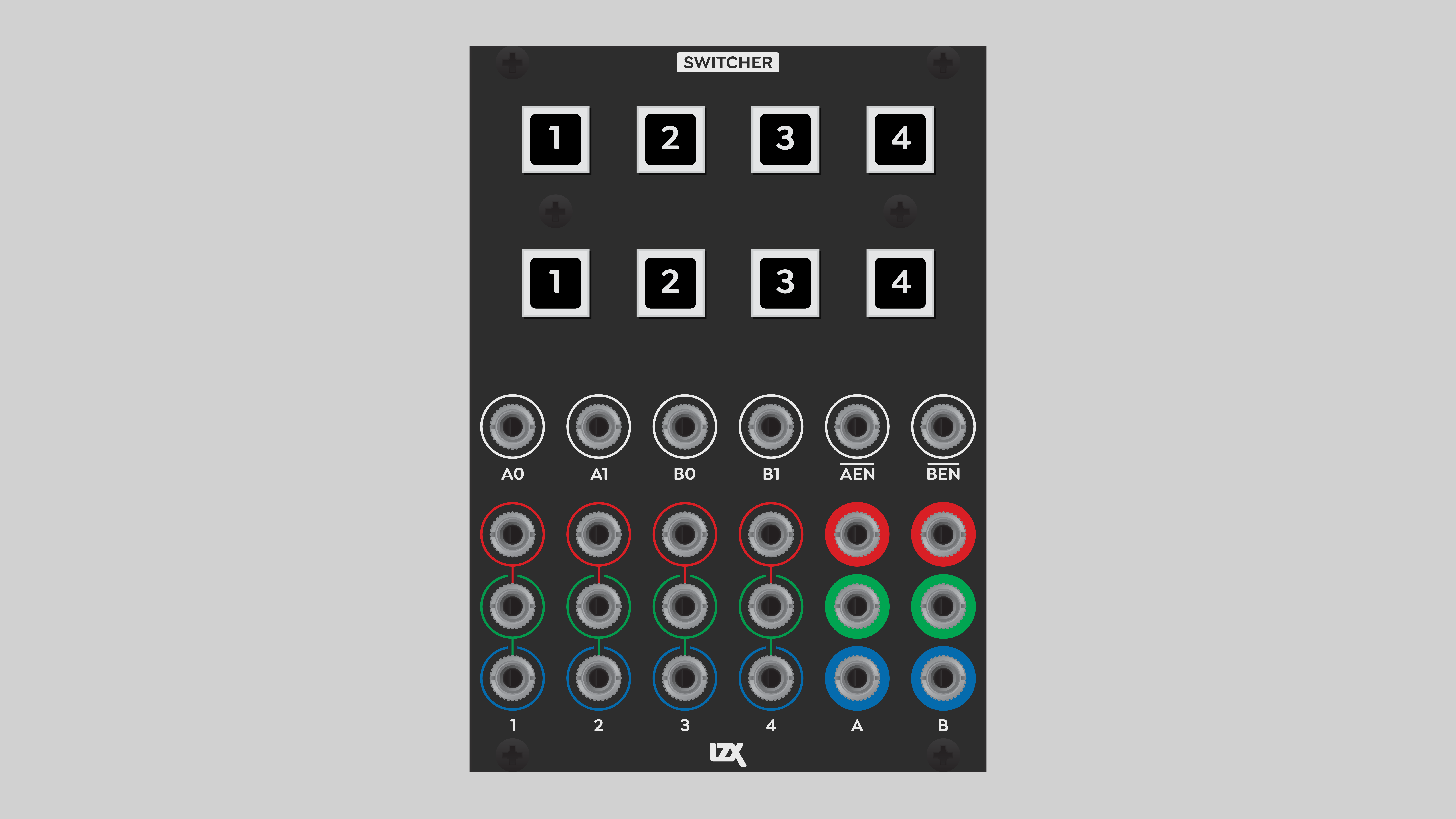
Controls, Connectors & Indicators
Four sets of RGB inputs, labeled 1 through 4, are found at the lower left of Switcher. As always in Gen3, the inputs are internally normalled, so that a signal cascades down to the inputs below it. For monochrome signals, patch into the top, Red row of inputs.
Two sets of RGB outputs, labeled A and B, are located at the lower right. The outputs are completely independent of one another.
Manual selection is performed with the illuminated buttons at the top of the module. The upper row of buttons selects the input routed to the A output. The active A input button is illuminated in green. The lower row of buttons selects the input routed to the B output. The active B input button is illuminated in white.
Below the buttons is a row of Control Inputs. To the left are the A bus Select inputs, labeled A0 and A1. These binary inputs define a two-bit number to select one of the RGB inputs, as described below. Immediately to the right of the A bus Select inputs are the B bus Select inputs, labeled B0 and B1.
On the right of the module are Disable inputs, labeled and . The bar over the letters is called a macron, and in this context it indicates logical negation. The input label means "not enable", or disable.
Operation
Manual selection
The most basic function of Switcher is to manually select a single RGB triplet, routing it to one of the A or B RGB outputs. Just punch a button, and the corresponding RGB input is sent to an output. The inputs and outputs are not exclusive, so we can send the same signal to both outputs if desired. Manual switching is performed in the vertical interval between frames or fields, eliminating the tearing that occurs when a sudden transition happens in the middle of a frame.
Control inputs
But that's hardly scratching the surface. Each of the A and B busses has three Control Inputs: two Select inputs and one Disable input. All control inputs are binary, and operate at video rate. A high-speed comparator at each Control Input slices the incoming signal at a value of 0.5 volts. A signal above that threshold is interpreted as "on", or a binary value of 1. A signal below the threshold is interpreted as "off", or a binary value of 0.
Each pair of Select inputs makes up a two-bit binary number, with four possible values — one for each of the four RGB inputs. The A0 and B0 Select inputs are the most significant bit (MSB), or the "twos place" of the two-bit number. The A1 and B1 inputs are the least significant bit (LSB), or the "ones place" of the two-bit number.
RGB input selection is determined by the interaction of the Select inputs and the panel buttons. The active button shifts the Select value by one bit for each button above 1. If input 1 is active, the Select value is shifted by zero bits. If input 2 is active, the Select value is shifted by one bit, and so on. The Select value wraps around back to the starting input. Regardless of the active RGB input, any combination of Select input values always yields a valid selection of RGB inputs.
Assuming that input 1 is active, the following table shows the results of sending binary values to the Select inputs.
| Select 0 input (MSB) | Select 1 input (LSB) | Binary value | Decimal value | RGB input |
|---|---|---|---|---|
| 0 | 0 | 00 | 0 | 1 |
| 0 | 1 | 01 | 1 | 2 |
| 1 | 0 | 10 | 2 | 3 |
| 1 | 1 | 11 | 3 | 4 |
Supplying only one bit of information to a Select input is not enough to address all four outputs. For example, if we don't patch anything into the Select 1 input, then the least significant bit will always be 0. In that case, the Select 0 input will give a binary value of 00 or 10, switching between RGB inputs 1 and 3.
The Select inputs are video rate, which makes each output bus of Switcher a four-layer compositor! Key outputs from Keychain, Stacker, Ribbons, etc. can be used to build up complex RGB layering effects within Switcher. If the RGB sources are static voltages from 2x Matte or Proc, Switcher operates as a four-level posterizer.
The A and B outputs of Switcher can each be blanked off with a dedicated Disable control input. Any voltage above 0.5 will disable the output. Just like the Select inputs, the Disable inputs operate at video rate, allowing an image or pattern to mask off areas of the Switcher output.
A static voltage above 0.5 at one of the Disable inputs will completely blank out that bus.
Extended applications
Any unipolar signal can be processed by Switcher. It can handle many tasks besides routing RGB signals. Select different modulation sources, cycle through ramp generator angles or waveshapes, or send a feedback loop through different paths.
The two independent busses of Switcher enable a wide variety of different automated routing options. For example, one bus can handle video, while the other handles low frequency modulation.
Installation
Requirements
- EuroRack enclosure
- 12V DC or EuroRack power supply
- 2.1mm DC barrel power cable or a EuroRack power cable (both options included)
- Four M2.5 x 6mm mounting screws, or screws provided or specified by the enclosure manufacturer
- #1 Phillips head screwdriver, or hand tool provided or specified by the enclosure manufacturer
Procedure
- Power off and disconnect the EuroRack enclosure's power supply and any attached DC adapters.
- Connect either the EuroRack Power Cable or the DC Barrel Power Cable to the module. Do not connect both Eurorack and DC Barrel power.
- Ensure that no mounting screws are in any holes in the area where you wish to mount the module.
- Carefully test fit the module with its attached power cable in the open space in the EuroRack enclosure. If it is obstructed by the enclosure or any internal assemblies, abort this procedure.
- Connect the disconnected end of the power cable to the power supply.
- Connect the sync cable to a sync source, such as a sync DA or the last module in the existing sync chain.
- Mount the module to the EuroRack rails using all mounting holes.
- Store the unused cable along with the product box in a safe location.
- Power on the EuroRack enclosure and start patching.
Full Specifications
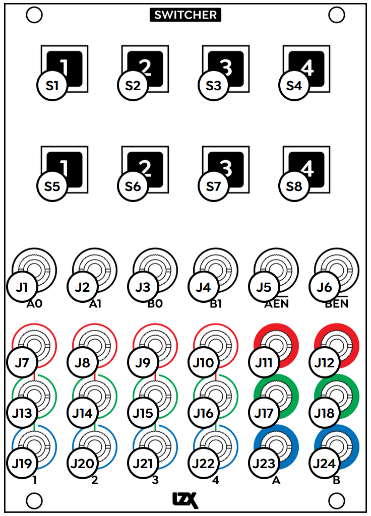
| Front panel | Connectors | Connectors and Controls | ||||||||||||||||||||||||||||||||||||||||||||||||||||||||||||||||||||||
|---|---|---|---|---|---|---|---|---|---|---|---|---|---|---|---|---|---|---|---|---|---|---|---|---|---|---|---|---|---|---|---|---|---|---|---|---|---|---|---|---|---|---|---|---|---|---|---|---|---|---|---|---|---|---|---|---|---|---|---|---|---|---|---|---|---|---|---|---|---|---|---|---|
 |
|
|
Technical Data
| Parameter | Value |
|---|---|
| Manufacturer Part Number | 950057 |
| Mounting Width | 18 HP |
| Mounting Depth | 32 mm |
| Mounting Hole Count | 4 |
| Power Consumption | 12V @ 210 mA |
| Power Connectors | 16 pin EuroRack ribbon, 2.1mm DC barrel |
| Input Impedance | 1M ohms |
| Output Impedance | 75 ohms |
| Input Protection Range | +/-20V |
| Input Clipping Range | +/-2.5V |
| Output Range | +/-2.5V |
| Included | DC barrel power cable, EuroRack power cable |
| EuroRack Power Cable Type | 16-pin |
| EuroRack Power Cable Length | 25 cm |
| DC Barrel Power Cable Length | 25 cm |
| RoHS Compliance | Manufactured with lead-free processes |
| Video Sync | Rear RCA in and out |
Maintenance
Keep the module free of dust and debris by performing periodic cleaning. Spots may be cleaned from the front panel with a microfiber cloth and isopropyl alcohol or other electronics cleaner.
Hardware Revisions
The hardware revision code is printed on the circuit board visible from the rear of the module.