SCROLLS
Overview
Scrolls is a high precision motion controlled dual waveform generator for SD and HD modular video synthesis. It provides full control over two independent sets of video waveforms. Front panel switches provide access to 72 combinations of speed, waveform blanking and mirroring, and advanced motion paths ranging from elliptical orbit to random walk.
Basic generative synthesis patches begin with horizontal and vertical ramps. These define 2D Cartesian coordinates in screen space. With motion controlled ramps, the coordinate system itself is shifted, repositioning or animating the entire resulting pattern.
Scrolls also outputs four dedicated low frequency control voltages. These LFOs control the movement of the video waveforms. Use them to animate the patch in other ways, dancing in time with Scrolls.
Random and Journey modes conjure autonomous entities moving in screen space. Let your figure or pattern wander through the video world, or teleport in strobing patterns of random phases. In any mode, you always set the tempo. Even chaos can to step to the beat.
Legacy
Scrolls is the third iteration of precision motion control from LZX. The first high-level animation module was the prototype Scroll & Position Controller. That was never released, but some of its features manifested in the Orion series module Diver. The design intentions of Diver and Scrolls are somewhat different. Diver's focus was generating a variety of 2D patterns, whereas Scrolls is all about procedural animation. Scrolls doesn't have a memory, but it has many fascinating innate behaviors.
Key Specifications
| Parameter | Value |
|---|---|
| Mounting Width | 12 HP |
| Power Consumption | 12V @ 150 mA |
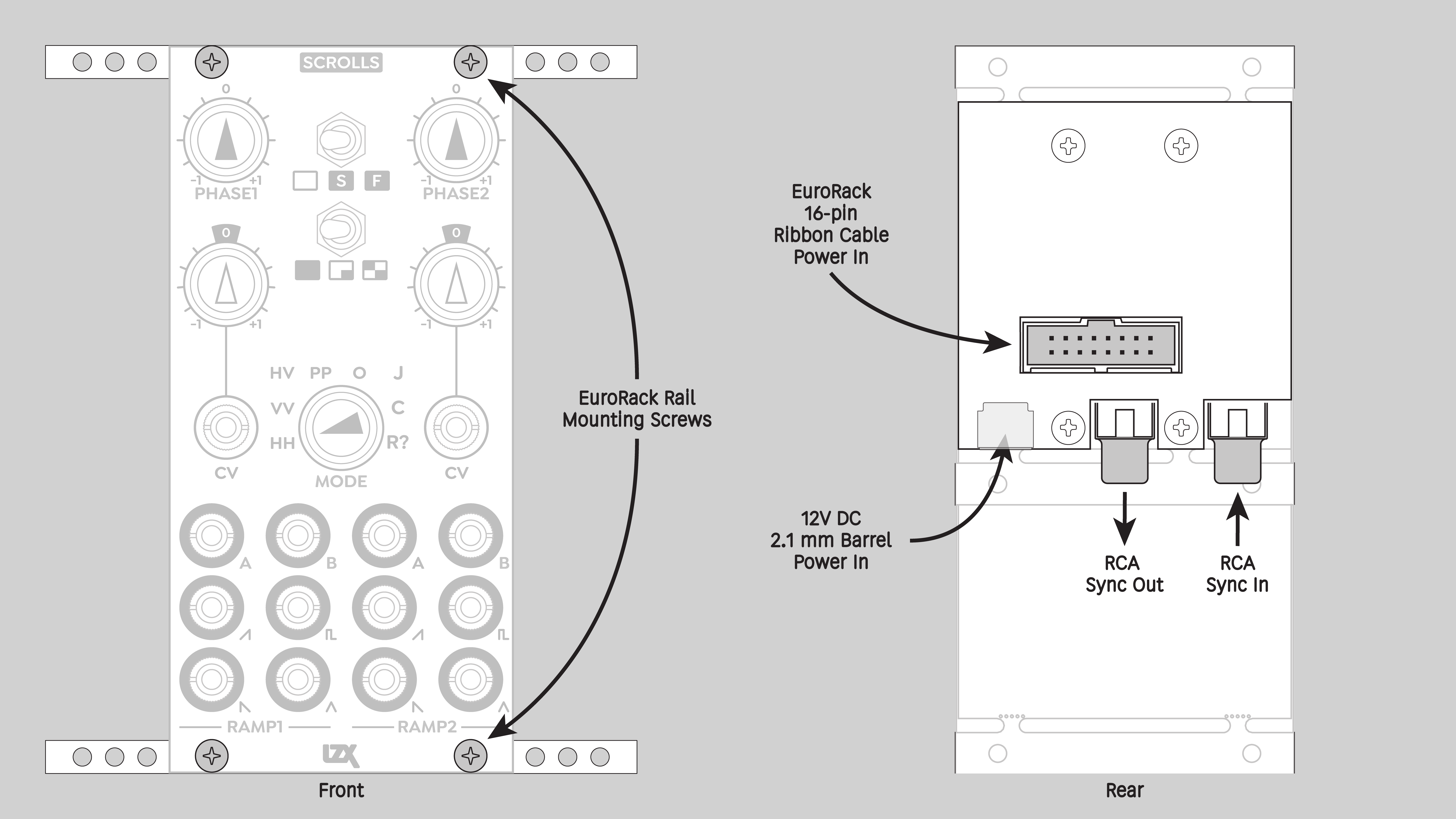
| Power Connectors | 16 pin EuroRack ribbon, 2.1mm DC barrel |
| Video Sync | Rear RCA |
| Included | DC barrel power cable, EuroRack power cable, RCA sync cable |
System Integration Advice
Scrolls is a unique and powerful engine for generative video synthesis. In a pure generative synthesis pipeline, Scrolls is an essential element. It can take your work in many new directions.
At the most fundamental level, Scrolls allows smooth horizontal motion. In analog generative video synthesis, vertical motion is easy. Just tune an oscillator to a frequency in the low audio range. But smooth horizontal motion can be difficult with conventional analog oscillators due to instability at high frequencies. There is a workaround involving an LFO and wavefolding, but that introduces horizontal pattern symmetry whether you like it or not.
Lacking horizontal motion, our creative options are super limited. Scrolls solves this problem with high precision digital waveforms. It's an essential tool for taking generative video beyond the basics. The various modes give you many tools for creating engaging real-time animation, and the synchronized CV outputs expand those possibilities in countless ways.
Scrolls is a primary element of a generative video system. It provides the base fabric on which rich tapestries can be woven. Other important modules in such a system might include DSG3, DWO3, Angles, Stairs, Keychain, Contour, and Stacker.
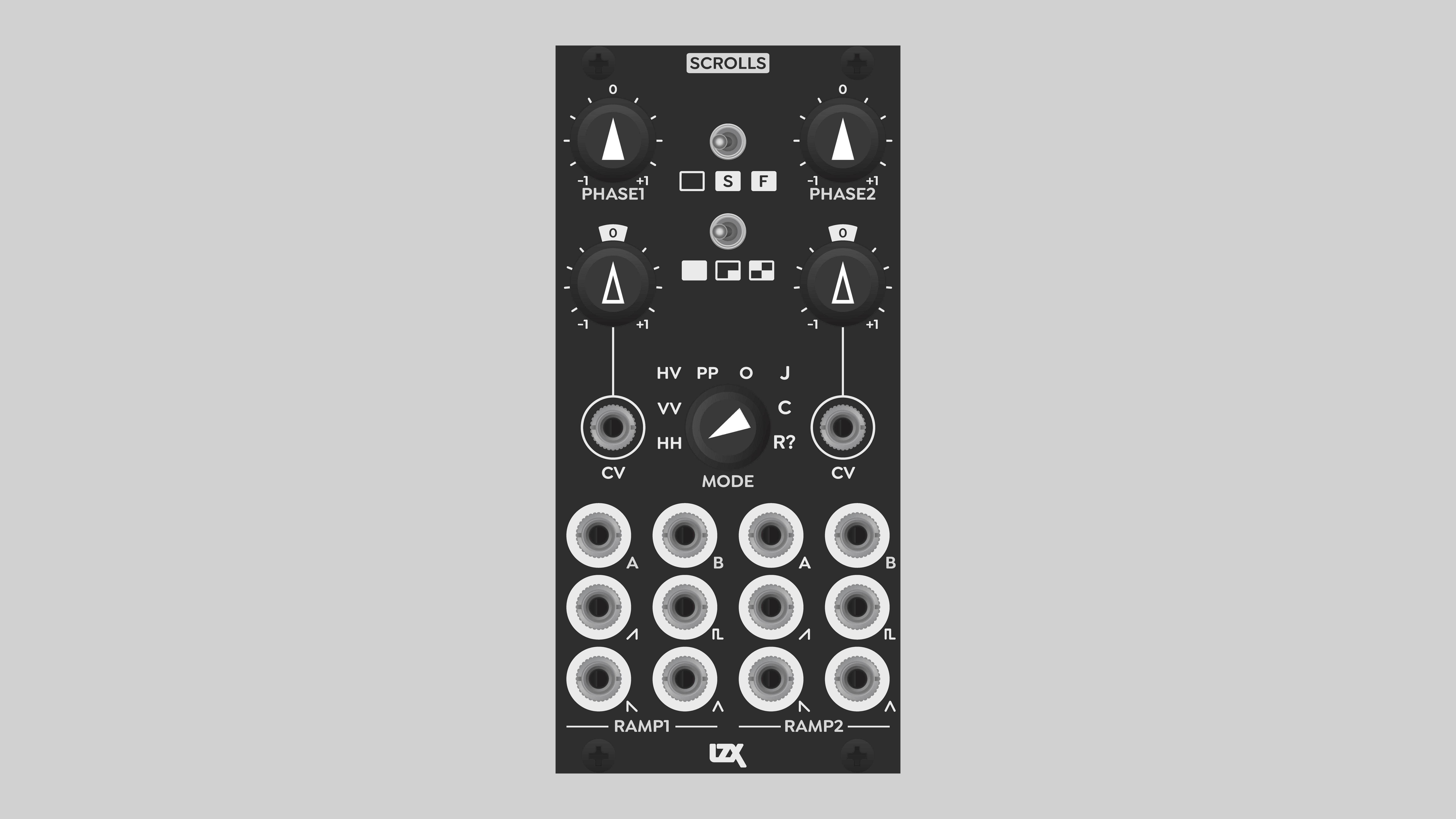
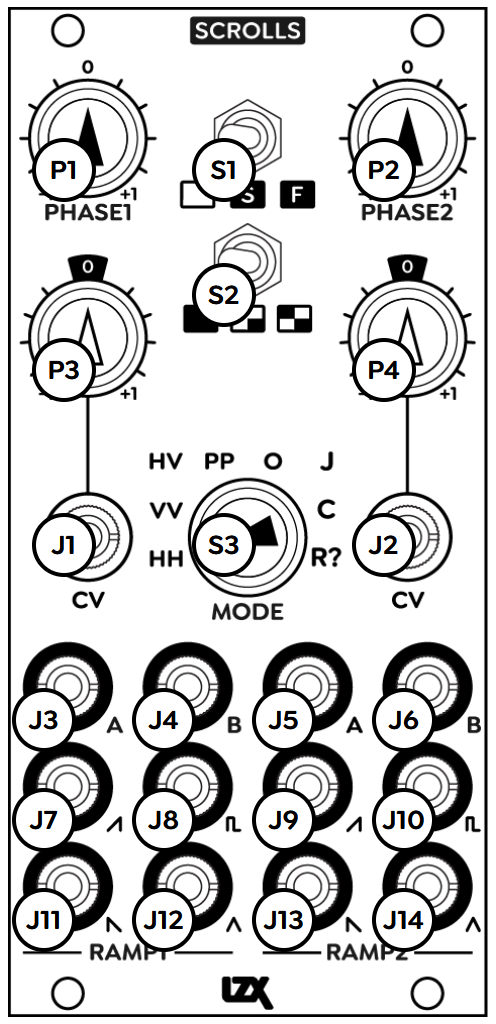
Controls & Connectors
Scrolls is a rhythm source, almost like the visual version of a drum machine. It packs a great deal of functionality into a small package of 12 HP, with no menu diving.
Two identical submodules, Ramp 1 and Ramp 2, provide independent inputs and outputs.
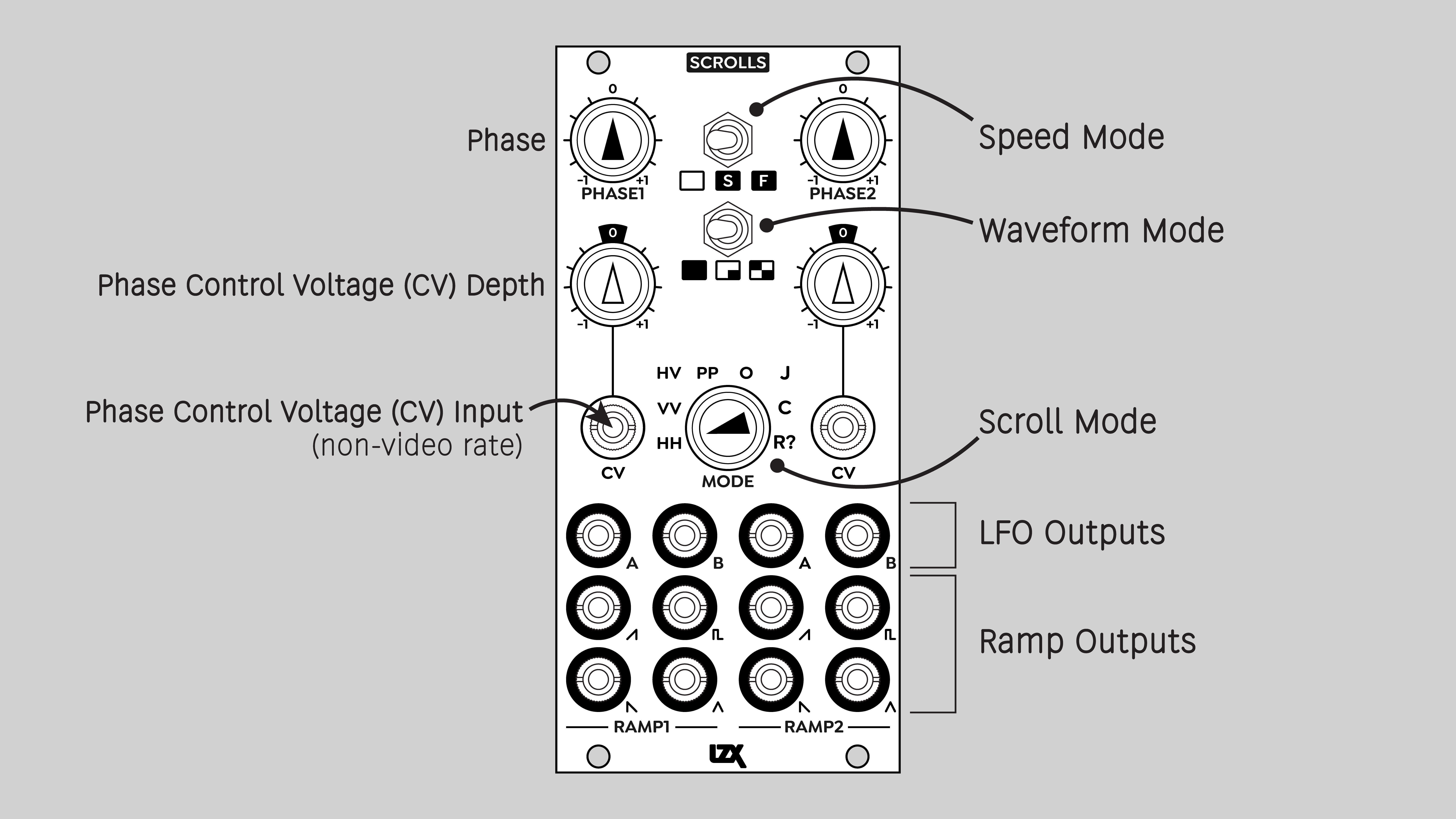
The primary global Mode of Scrolls is chosen from the eight-position rotary switch in the center of the panel. This selects whether H or V signals are available from the video generator jacks, and how all motion is controlled.
Two three-position toggle switches choose other global options. The top switch selects the Speed mode. The switch directly below that selects the Waveform mode.
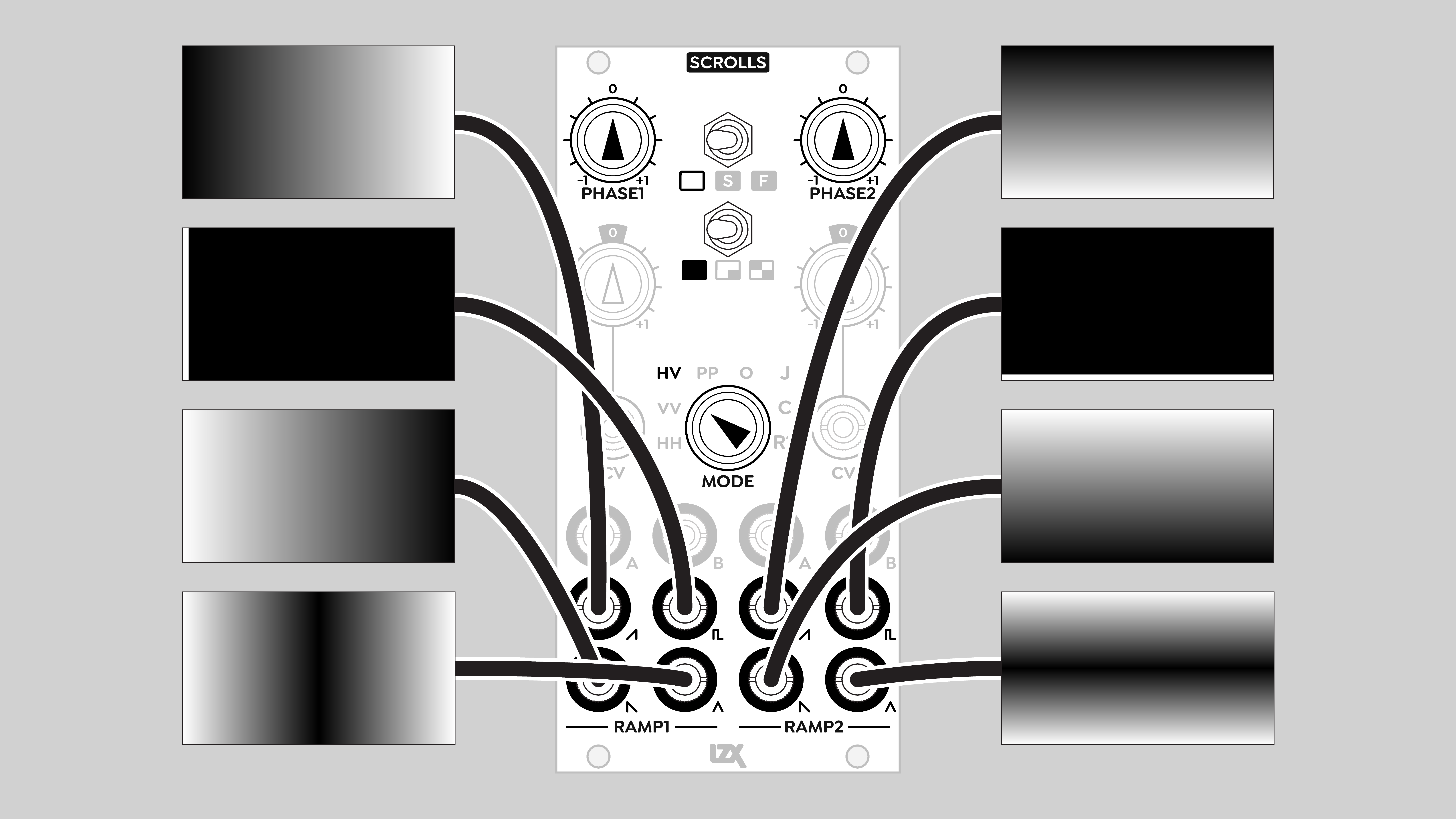
As the primary driver of a generative video patch, Scrolls features numerous outputs. The two bottom rows of jacks are the video waveform generators. Each Ramp submodule provides the following outputs: Ramp (rising), Pulse, Sawtooth (falling), and Sine.
Above the video outputs is a row of low frequency control voltage outputs. Each Ramp submodule features two LFO outputs, labeled A and B.
Per each Ramp Submodule, a bipolar Phase potentiometer shifts the position of the generator, or controls the motion in some other way. The Phase value can be driven by a control voltage supplied to the CV jack. The incoming phase CV is multiplied by the value set with the Phase CV Depth attenuverter potentiometer.
Operation
Speed
Choose from three ranges of motion speeds. The top toggle switch selects one of three modes, from left to right: Motion Disabled, Slow Range, and Fast Range.
Motion Control Disabled
When Speed is set to Motion Disabled, the Phase1 and Phase2 knobs directly control the phase of the video waveforms. They also set the speed of the LFOs. In this mode, the LFOs run at the same frequencies as in Slow Range. However, the LFOs do not affect the video waveforms.
In Motion Disabled mode, the effect of turning Phase1 and Phase2 knobs is to offset the video waveforms. Horizontal ramps are shifted side-to-side, vertical ramps are shifted up and down.
The relationship between the knob position and the ramp position is linear in all cases except Journey Motion Control mode. In Journey mode, Phase1 sets an angular value, which is the two-dimensional direction of an offset to both sets of video waveforms. Phase2 sets the amount of offset to both sets of video ramps, in the direction set by Phase1.
Motion Control Enabled
When Speed is set to Slow Range or Fast Range, the phase of the video waveforms is controlled by the LFOs. Phase1 and Phase2 knobs adjust the speed of the LFOs.
Phase CV inputs
A low frequency signal supplied to Phase1 CV or Phase2 CV allows automation of the phase of the video waveforms and/or the LFO frequencies. The value of the incoming voltage is multiplied by the associated Phase CV Depth attenuverter, and added to the value of the associated Phase knob.
The same rules apply whether or not Phase receives a control voltage. In Motion Disabled mode, the LFOs don't affect the video waveforms. In Slow Range or Fast Range modes, the video waveforms are modulated by the LFOs.
The Phase CV inputs can technically accept any LZX-compatible voltage, but the Scrolls engine is not designed for video-rate modulation, or even for instantaneous transitions. There's always a split-second slew applied to any change in Phase.
For example, if you plug a video signal into a Phase CV input, you'll probably get chaotic results. This may be interesting and useful as an effect, but you can't modulate with a video image like you can with an analog oscillator such as DWO3. Or if you plug a low frequency square wave into Phase CV, you won't get video waveforms instantly jumping from one position to another, you'll get snappy movements between two positions.
Waveform
Choose from three waveform modes. The toggle switch selects one of three modes, from left to right: Wrap, Blank, and Mirror.
Wrap
The ramp phase scrolls continuously, repeating across the screen.

Blank
The ramp phase can be shifted entirely offscreen.

Mirror
The ramp phase inverts on every other cycle. The result is a scrolling virtual canvas, double the width and double the height of the video image.
In HD timing formats, a 20ns black line is visible when the ramp reflects from positive to negative slopes. This is known behavior.
Motion Control Modes
HH: Double Horizontal
Both Ramp 1 and Ramp 2 video waveforms are horizontal, with separate Phase controls.
LFO A is a sine wave. LFO B is a rising ramp in phase with LFO A, such that the lowest values of the two oscillators happen at the same time.
VV: Double Vertical
Both Ramp 1 and Ramp 2 video waveforms are vertical, with separate Phase controls.
LFO A is a sine wave. LFO B is a rising ramp in phase with LFO A, such that the lowest values of the two oscillators happen at the same time.
HV: Horizontal & Vertical
Ramp 1 video waveforms are horizontal, Ramp 2 video waveforms are vertical.
LFO A is a sine wave. LFO B is a rising ramp in phase with LFO A, such that the lowest values of the two oscillators happen at the same time.
PP: Ping Pong
Ramp 1 video waveforms are horizontal, Ramp 2 is vertical. Motion uses triangle waves, for the bouncing DVD player logo effect.
LFO A is a triangle wave. LFO B is a sine wave, in phase with LFO A.

O: Orbital
Ramp 1 video waveforms are horizontal, Ramp 2 video waveforms are vertical. Motion uses a quadrature sine wave generator to animate the video waveforms in an elliptical orbit matching the aspect ratio of the video frame. Phase 1 controls speed, Phase 2 controls depth.
LFO A and LFO B are sine waves. LFO B is 90 degrees out of phase relative to LFO A.
J: Journey
Ramp 1 video waveforms are horizontal, Ramp 2 video waveforms are vertical. Motion is similar to HV mode, but speed and direction are based on polar coordinates instead of a Cartesian XY grid. Phase 1 controls the angular direction of motion, Phase 2 controls speed.
LFO A and LFO B are sine waves. LFO B is 90 degrees out of phase relative to LFO A. The frequency of both LFOs is affected by both Phase parameters, in a complex nonlinear relationship resulting from the polar coordinates.
In journey mode, increasing the Phase may have the counterintuitive result of decreasing the frequency of LFOs.
C: Corner
Ramp 1 video waveform is horizontal, Ramp 2 is vertical. Phase 1 controls speed, Phase 2 controls depth. Motion is similar to Orbital mode, but uses slewed trapezoid waveforms rather than sines. This gives pleasing “slow-out, slow-in” changes in speed.
LFO A and LFO B are “s-curve” slewed trapezoid waves. LFO B is 90 degrees out of phase relative to LFO A.
R?: Random
Ramp 1 video waveform is horizontal, Ramp 2 is vertical. Phase 1 controls speed. Phase 2 controls depth, which is the amplitude of the chaotic waveforms.
Two chaotic modes are available, determined by the position of the Phase 2 knob. In the counterclockwise range to the left of 12 o'clock, the random values are punctuated by sudden movements and periods of momentary stillness. In the clockwise range to the right of 12 o'clock, the random values are smoothly interpolated, similar to the fluctuating random voltages found in audio modules such as the Buchla 266 Source of Uncertainty.
LFO A and LFO B are independent chaotic waveforms.
Example Patches
Reset DWO3
Stairs
Installation
Requirements
- EuroRack enclosure
- 12V DC or EuroRack power supply
- 2.1mm DC barrel power cable or a EuroRack power cable (both options included)
- Four M2.5 x 6mm mounting screws, or screws provided or specified by the enclosure manufacturer
- #1 Phillips head screwdriver, or hand tool provided or specified by the enclosure manufacturer
Procedure
- Power off and disconnect the EuroRack enclosure's power supply and any attached DC adapters.
- Connect either the EuroRack Power Cable or the DC Barrel Power Cable to the module. Do not connect both Eurorack and DC Barrel power.
- Ensure that no mounting screws are in any holes in the area where you wish to mount the module.
- Carefully test fit the module with its attached power cable in the open space in the EuroRack enclosure. If it is obstructed by the enclosure or any internal assemblies, abort this procedure.
- Connect the disconnected end of the power cable to the power supply.
- Connect the sync cable to a sync source or the last module in the sync chain.
- Mount the module to the EuroRack rails using all mounting holes.
- Store the unused cable along with the product box in a safe location.
- Power on the EuroRack enclosure and start patching.
Full Specifications
| Connectors | Controls | |||||||||||||||||||||||||||||||||||||||||||||||
|---|---|---|---|---|---|---|---|---|---|---|---|---|---|---|---|---|---|---|---|---|---|---|---|---|---|---|---|---|---|---|---|---|---|---|---|---|---|---|---|---|---|---|---|---|---|---|---|---|
 |
|
|
Technical Data
| Parameter | Value |
|---|---|
| Manufacturer Part Number | 950001 |
| Mounting Width | 12 HP |
| Mounting Depth | 42 mm |
| Mounting Hole Count | 4 |
| Power Consumption | 12V @ 150 mA |
| Power Connectors | 16 pin EuroRack ribbon, 2.1mm DC barrel |
| Input Impedance | 1M ohms |
| Output Impedance | 75 ohms |
| Input Protection Range | +/-20V |
| Input Clipping Range | +/-2.5V |
| Output Range | +/-2.5V |
| Included | DC barrel power cable, EuroRack power cable, RCA sync cable |
| EuroRack Power Cable Type | 16-pin |
| EuroRack Power Cable Length | 25 cm |
| DC Barrel Power Cable Length | 25 cm |
| RoHS Compliance | Manufactured with lead-free processes. |
| Video Sync | Rear RCA in and out |
Maintenance
Keep the module free of dust and debris by performing periodic cleaning. Spots may be cleaned from the front panel with a microfiber cloth and isopropyl alcohol or other electronics cleaner.
Hardware Revisions
The hardware revision code is printed on the circuit board visible from the rear of the module.
Firmware Update
Requirements
- Your module.
- A PC running Windows, Mac or Linux.
- A USB Mini-B cable.
Connecting the Module
- Remove the module from your rack and disconnect any EuroRack or DC power cables.
- Connect the USB Mini-B cable to the USB connector on the rear of the module.
- Connect the other end of the USB cable to apowered USB port on your PC.
Downloading the Firmware
-
Download the current firmware package: Scrolls Firmware 1.0.3
-
Extract the downloaded archive and verify that you have a file with the .BIN file extension.
Updating the Firmware
Installing LibUSB Drivers (Windows Only)
For future updates, this step will be unnecessary when using the same PC.
- Download a recent release of the Zadig application from https://zadig.akeo.ie and open the executable file.
- Select Options > List All Devices.
- Select STM32 BOOTLOADER from the dropdown device list.
- Select WinUSB and then reinstall or replace the driver.
Installing the Firmware Binary
- Visit the WebDFU tool at https://devanlai.github.io/webdfu/dfu-util.
- Click the Connect button and select STM32 BOOTLOADER from the list.
- Select the option for Internal Flash and click Select Interface.
- Under Firmware Download, click Choose File and select the .BIN file downloaded during the previous step.
- Click Download and wait for the process to complete.
- Disconnect your module from the USB cable and reinstall it in your EuroRack system.