STAIRS
Overview
Stairs is a six-stage video wavefolder and frequency multiplier. It creates a variety of fascinating visual effects such as multi-stage frequency doubling, solarization, and colorization. Just as an audio wavefolder produces rich timbres from simple waveforms, Stairs adds layers of visual complexity to any video image or pattern.
Stairs features an RGB input, with three jacks internally normalled, weighted, and summed according to the video luminance formula. Although Stairs is a monochrome module, any of its six outputs can be patched to produce complex colorization effects. For example, send Stairs outputs to the RGB inputs of ESG3. Concentric shapes of varying frequencies are combined, resulting in multi-band, continous-tone colorization.
Voltage control over the Steps and Phase parameters provide levels of creative control than can't be achieved with a simple wavefolder. Varying the amount of folding and offset with a video-rate control voltage results in even more complex imagery. Map the value of an image onto the fold amount, giving nonlinear and fractal-like qualities to the outputs.
The high-gain multiplication circuitry of Stairs can also be employed to generate chaotic visual patterns. For a variety of noisy textures such as video "snow", patch a source into Stairs, then feed Stairs back into itself.
Legacy
Stairs is the second-generation dedicated video wavefolder from LZX. It was preceded by the Expedition series module Staircase. Stairs offers more options for input and output. Up to three sources can be patched to the Stairs inputs. All of the multiplication stages are available as independent outputs, including a very high frequency 64x stage.
Stairs omits the internal modulation routing of the Staircase Harmonics switches. The Phase control on Stairs biases the signal, whereas on Staircase it's a gain multiplier. The Stairs Phase shifts the value ranges up or down, creating blank areas or "negative space" in the outputs.
Key Specifications
| Parameter | Value |
|---|---|
| Mounting Width | 8 HP |
| Power Consumption | 12V @ 210 mA |
| Power Connectors | 16 pin EuroRack ribbon, 2.1mm DC barrel |
| Included | DC barrel power cable, EuroRack power cable |
| Video Sync | None |
System Integration Advice
Stairs is the most advanced video wavefolder available. Its unique creative potential makes it a very popular module. No other commercial tool, analog or digital, can do what Stairs does.
Simpler variations on the wavefolder circuit are available in PRM and DSG3. Those are single- or double-stage folders without voltage control. PRM also features half-wave rectified outputs, isolating the high and low value ranges of the source signal to independent wavefolded outputs. Stairs achieves this effect via the Phase control, but only for a single value range at a time.
Each implementation has its advantages. PRM is extremely precise, DSG3 is optimal for animated effects such as color cycling, and Stairs gives the greatest range of complexity.
Controls & Connectors
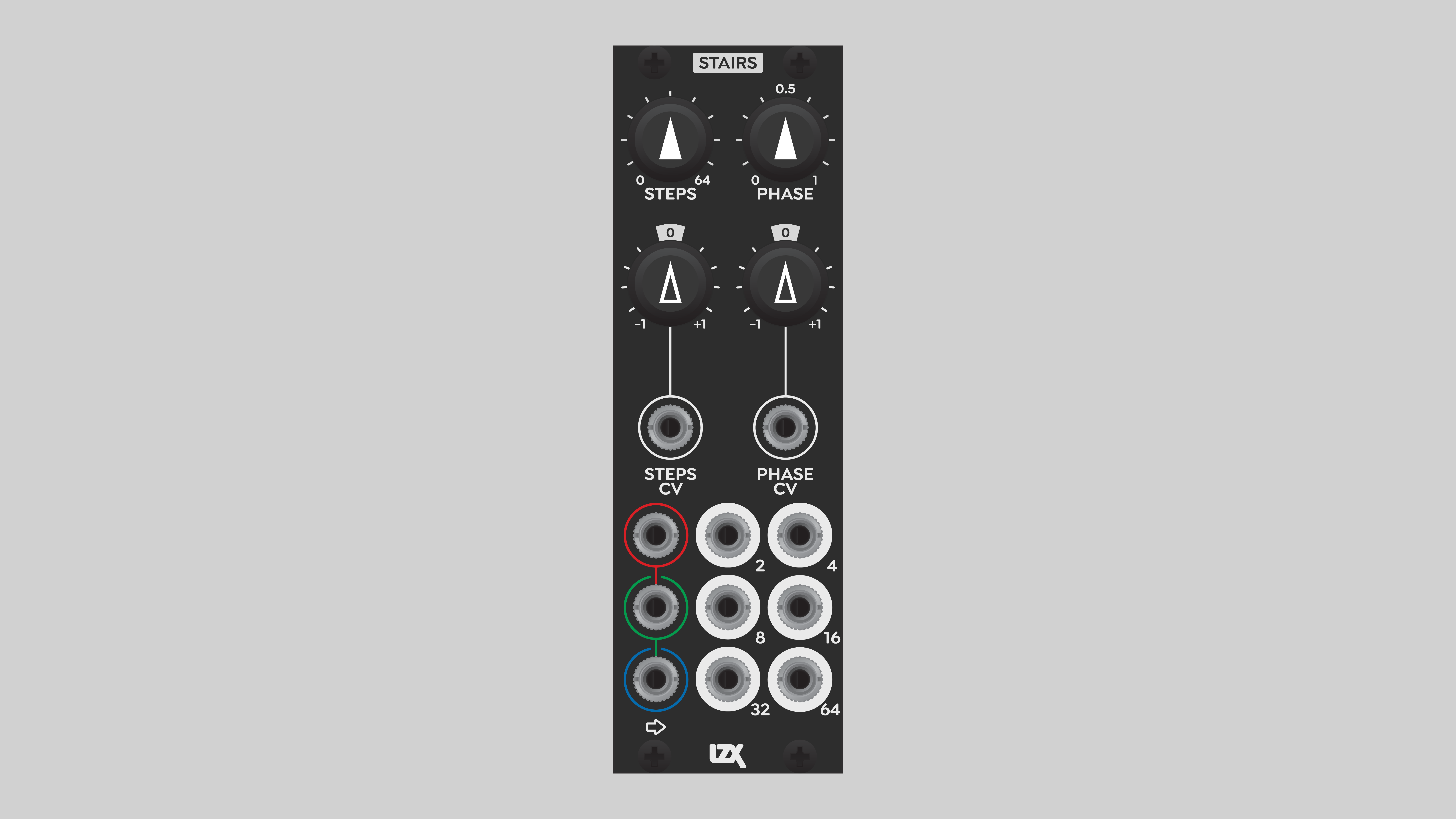
Stairs features three primary signal inputs, two control voltage inputs, and six outputs.
The signal inputs at the lower left are color-coded for red, green, and blue color primaries, but as always, that's just a suggestion. Any signals, including low frequency modulators, can be patched into the RGB inputs.
The RGB inputs are internally self-normalled, allowing a signal patched into a jack to flow downward to the other inputs. The inputs are weighted and summed, as described in the Operation section below.
Stairs has two voltage-controlled parameters: Steps and Phase. Each can be manually adjusted by the corresponding potentiometer on the top row. Additionally, any signal may be patched into the Steps CV or Phase CV jacks in the center of the module. The gain of those incoming control voltages is adjusted with the corresponding Depth attenuverters. Counterclockwise rotation, to the left of 12 o'clock, inverts the incoming control signal.
Each of the six outputs provides access to a different stage of the wavefolder circuit. The frequency of the input signal is doubled at each output stage, resulting in a series of frequencies increasing by powers of two. The first output stage doubles the input signal, the second stage doubles it again, and so on. Each output is labeled according to the output frequency.
Operation
RGB Signal Inputs
RGB inputs are weighted and summed according to the luminance formula fully explained in the TBC2 documentation. Patch an RGB signal triplet into the corresponding color-coded inputs to convert RGB to luminance before it hits the wavefolder circuit.
A single signal patched into the Red input is buffered and duplicated to the Green and Blue inputs below it. After the three normalled inputs are weighted and summed, the resulting monochome signal sent to the folder is identical to the source patched into Red.
A single signal patched into the Green or Blue input results in a gain reduction before the folding stages. Patching into Green yields a signal strength of approximately 0.7. Patching into Blue yields a signal strength of only approximately 0.1. These are very useful options in certain applications such as feedback self-patching to create noise textures. Patching into the Blue input greatly attenuates the signal, helping to avoid runaway feedback that results in a blank output.
Different signals can be patched into RGB inputs to achieve a variety of effects. For example, patch a video source into the Red or Green input, and a low frequency source into the Blue input. The weighted summing of the RGB inputs results in a biasing modulation, shifting values up and down before the folding stage. It's similar to the Phase CV input described below. The effect can be combined with voltage control modulation of the Steps and/or Phase parameters. Or send different monochome video sources into the RGB inputs for internal layering of multiple images.
Steps and Phase
Steps sets the degree to which an incoming signal is folded by simply attenuating it before the folding circuit. This gives the visual result of variable frequencies "in between" those of the raw outputs. For example, if we take the 4x output of Stairs and reduce the Steps parameter, we can get three concentric bands instead of four.
Phase sets the "starting point" of the frequency doubling cicuit by biasing the incoming signal. A non-zero Phase amount shifts incoming value tones to higher values, "cropping" the lower source values. Any input value below the Phase value is not folded, and the resulting output is black. The effect is essentially the same as the half-wave rectifier of PRM, except that Stairs allows a variable threshold.
Steps and Phase parameters can be voltage controlled. This opens up many creative possibilities, some of which are unique to Stairs. A simple example: crop the highlights instead of the darker, lower values. Send a static voltage source, typically +1v, into the Phase CV input, and turn the Phase CV Depth knob counterclockwise, to the left. This biases the incoming signal down instead of up.
Voltage control of Steps really shows off the unique capabilities of Stairs. Low frequency control signals such as sine or triangle waves make the frequency "breathe". It's an effect similar to frequency modulation of an oscillator -- except this applies to any video image, not just a simple waveform!
Sending a video signal into Steps CV takes us into very interesting territory: frequency modulating an image with another image! Multing the same image into both the RGB signal inputs and the Phase CV jack results in a nonlinear frequency response, where the brightness of the image determines the number of folds. The concentric bands are not uniform, but vary in width depending on brightness.
Feedback, Chaos, and Noise
Feeding an output back into an input of the same circuit is an easy and effective way to achieve chaotic, unpredictable patterns in space and time. Stairs exemplifies this concept in its ability to generate a range of noisy image textures such as TV "snow".
Most feedback circuits require some initial value to get the process started. For Stairs, all we need to do is send a static voltage into one of the RGB inputs, and feed a Stairs output back into one of the Stairs inputs. Various configurations are possible, giving different results. But only a low initial value is required. If the incoming static voltage is too high, the feedback will spiral out of control, giving no output at all. Try sending a voltage from Proc or Matte into the Blue input of Stairs, which attenuates the incoming static voltage to approximately 1/10th. Send one of the outputs of Stairs into the Steps CV input. Season to taste.
Stairs uses high gain amplifier circuits to bump the output levels up to full range. These are needed because each stage of the wavefolder cuts the amplitude of the signal in half. A by-product of a high gain amplifier is noise. All analog circuits generate thermal noise that's truly random, not just chaotic and unpredictable. Usually, we want to eliminate thermal noise, or at least keep it below the threshold of perception. But in this situation, the noisy amplifier circuit is not a bug, it's a feature. Noisy textures from Stairs feedback are truly random, and can never be repeated, even under ideal conditions.
Low Frequency Applications
As always, a high-speed video module can also be an effective processor of low frequency signals. Stairs can convert a simple low frequency waveform to a highly complex or chaotic control signal. The same principles described above for video images can be applied to control signals. Layering two or more LFO's via the RGB signal and/or CV inputs results in a complicated looping sequence. Feeding a Stairs output back to a Stairs input can yield chaotic control signals.
Video Tutorial
3 Patches for Stairs
presented by Johnny Woods
Installation
Requirements
- EuroRack enclosure
- 12V DC or EuroRack power supply
- 2.1mm DC barrel power cable or a EuroRack power cable (both options included)
- Four M2.5 x 6mm mounting screws, or screws provided or specified by the enclosure manufacturer
- #1 Phillips head screwdriver, or hand tool provided or specified by the enclosure manufacturer
Procedure
- Power off and disconnect the EuroRack enclosure's power supply and any attached DC adapters.
- Connect either the EuroRack Power Cable or the DC Barrel Power Cable to the module. Do not connect both Eurorack and DC Barrel power.
- Ensure that no mounting screws are in any holes in the area where you wish to mount the module.
- Carefully test fit the module with its attached power cable in the open space in the EuroRack enclosure. If it is obstructed by the enclosure or any internal assemblies, abort this procedure.
- Connect the disconnected end of the power cable to the power supply.
- Connect the sync cable to a sync source or the last module in the sync chain.
- Mount the module to the EuroRack rails using all mounting holes.
- Store the unused cable along with the product box in a safe location.
- Power on the EuroRack enclosure and start patching.
Full Specifications
| Connectors | Controls | |||||||||||||||||||||||||||||||||||
|---|---|---|---|---|---|---|---|---|---|---|---|---|---|---|---|---|---|---|---|---|---|---|---|---|---|---|---|---|---|---|---|---|---|---|---|---|
 |
|
|
Technical Data
| Parameter | Value |
|---|---|
| Manufacturer Part Number | 950052 |
| Mounting Width | 8 HP |
| Mounting Depth | 32 mm |
| Mounting Hole Count | 4 |
| Power Consumption | 12V @ 210 mA |
| Power Connectors | 16 pin EuroRack ribbon, 2.1mm DC barrel |
| Input Impedance | 1M ohms |
| Output Impedance | 75 ohms |
| Input Protection Range | +/-20V |
| Input Clipping Range | +/-2.5V |
| Output Range | +/-2.5V |
| Included | DC barrel power cable, EuroRack power cable |
| EuroRack Power Cable Type | 16-pin |
| EuroRack Power Cable Length | 25 cm |
| DC Barrel Power Cable Length | 25 cm |
| RoHS Compliance | Manufactured with lead-free processes |
| Video Sync | None |
Maintenance
Keep the module free of dust and debris by performing periodic cleaning. Spots may be cleaned from the front panel with a microfiber cloth and isopropyl alcohol or other electronics cleaner.
Hardware Revisions
The hardware revision code is printed on the circuit board visible from the rear of the module.