SMX3
Overview
SMX3 is a flexible mixing and routing module with nine inputs and three outputs. Each input can amplify, attenuate, or invert a signal in a range from -2x to +2x.
The inputs form a matrix of three rows and three columns. They're internally normalled, allowing signals to cascade down from one patch point to another. This is the key to many creative operations such as outputting multiple distinct mixes of input signals. For example, send three color components to the top row of inputs, and mix them in any way imaginable for a startling array of colorization options.
SMX3 also excels at adjusting and combining low frequency control signals.
Core functions of SMX3 include:
- Add
- Subtract
- Attenuate
- Amplify
- Invert
- Colorize
Legacy
SMX3 is the second generation module of its type, preceded by the Visionary series Video Blending Matrix. SMX3 is simpler and much more compact. It has fewer channels and no switches. Features such as static voltages and Absolute difference modes are implemented in other Gen3 modules such as Proc and DSG3. This allows SMX3 to focus on its core function as a mixer. Unlike Video Blending Matrix, SMX3 also includes 2x amplifiers on each channel.
Key Specifications
| Parameter | Value |
|---|---|
| Mounting Width | 12 HP |
| Power Consumption | 12V @ 175 mA |
| Power Connectors | 16 pin EuroRack ribbon, 2.1mm DC barrel |
| Included | DC barrel power cable, EuroRack power cable |
| Video Sync | None |
System Integration Advice
Like Proc, SMX3 is a core element of any modular video synthesizer. The list of applications for SMX3 is very long. It's particularly valuable for controlling color, either in RGB or YIQ component space.
SMX3 doesn't generate any voltages, so it can't bias a signal. It pairs well with modules that provide static voltages, such as Proc, PGO, and Matte. These pairings enable greater creative flexibility. For example, SMX3 + Proc makes it possible to freely mix unipolar and bipolar signals such as YIQ color components from Swatch.
Two or more SMX3 modules greatly expand the potential for complex routing and mixing. For example, with two SMX3 modules, two RGB video sources could be colorized.
SMX3 can accept or output both positive and negative voltages. However, many modules such as encoders can't accept any voltage outside the range of zero to +1 volts.
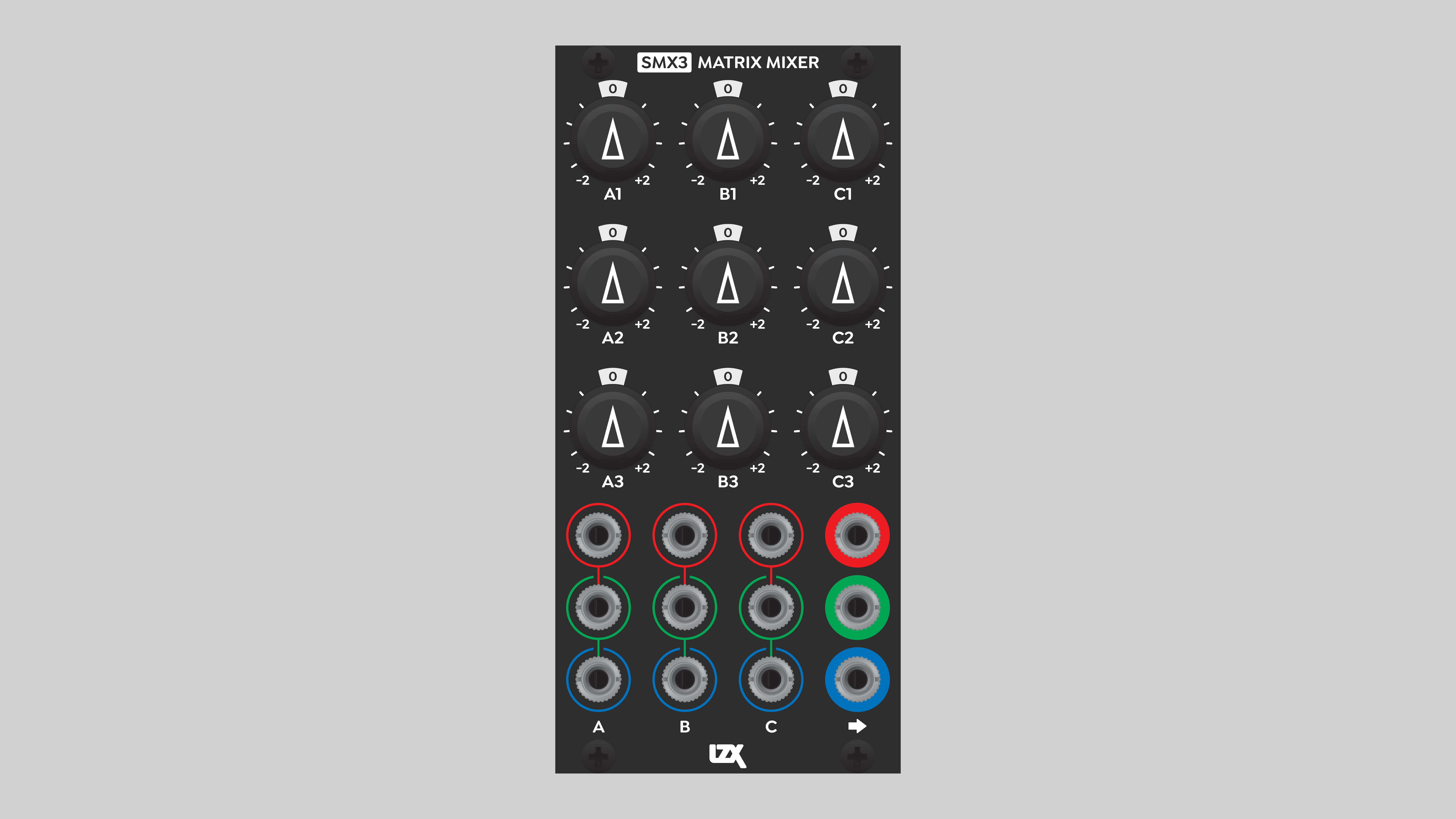
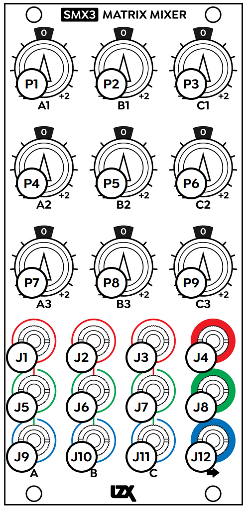
Controls & Connectors
The nine inputs of SMX3 are arranged in three rows, numbered 1, 2, and 3. The rows are color-coded as red, green, and blue, but any signal may be patched into the inputs. The sum of each row appears at the corresponding output on the right of the module. The internal normalling of the inputs allows signals to flow downward to the inputs below.
The three columns of inputs are labeled A, B, and C. Three inputs in each column allow the mixing of three signal triplets, such as RGB components.
Each of the nine inputs passes through a polarizer circuit controlled by the corresponding potentiometer, labeled A1 through C3. Unlike the attenuverters seen on many other LZX modules, the SMX3 pots are capable of +/- 2x amplification. At the center position, the multiplication factor of the incoming signal is zero, and the source is not added to the mix. Fully clockwise rotation amplifies the source by a factor of two. Fully counter-clockwise rotation multiplies the source by a factor of negative two. Some SMX3 front panels are labeled +1 and -1 to indicate approximate knob positions of positive and negative unity gain.
Operation
The simple interface of SMX3 makes it highly intuitive for a wide variety of mixing, routing, and signal processing operations. Each input can be amplified, attenuated, or inverted. Inputs in the same row can be added or subtracted from the mix. The number of possible applications is too many to list here. But, for example, we can subtract one video signal from another, then bias the mix with a low frequency control signal.
Thanks to the internal normalling, the three input/output rows can operate independently or in concert. In the above example of subtracting one video signal from another and biasing the mix, the video signals can be RGB triplets or independent single-channel signals. The low frequency control signal can affect any or all three outputs, simply by patching it into the appropriate row input. Patching into the top (red) row affects all outputs, the middle (green) row affects the second and third outputs, and the bottom (blue) row only affects the third (bottom) output.
Multiple-stage mixing
To mix more than three single-channel signals, patch one of the outputs of SMX3 to one of the inputs on a different row. In this way, a single SMX3 module can mix up to seven single-channel signals.
Mixing more than three signal triplets is accomplished with multiple SMX3 modules. Sending the output of one SMX3 to the input of a second SMX allows the mixing of up to five signal triplets.
Whenever patching SMX3 to itself, or to another SMX3, it makes sense to set the summed outputs to unity gain at the next input stage. In other words, if an SMX3 output is going to an SMX3 input, the best practice is to set the second-stage input potentiometer(s) to pass the incoming summed signal transparently, without amplification or attenuation. That way, there are no unpleasant surprises from multiple amplification stages. Final signal outputs equal the values set at their initial inputs.
Due to the DC amplification circuitry of SMX3, setting all potentiometers to the center position doesn't necessarily result in an output of zero volts. This may be a concern if you're not using all of the inputs. A small floating DC voltage may contribute the output, and changing the knob position of an unused input may shift that DC offset. If this is an issue, insert a dummy plug or zero voltage source to the unused input(s). The dummy plug must connect the tip to the sleeve.
Video Tutorial
3 Patches for SMX3
presented by Johnny Woods
Installation
Requirements
- EuroRack enclosure
- 12V DC or EuroRack power supply
- 2.1mm DC barrel power cable or a EuroRack power cable (both options included)
- Four M2.5 x 6mm mounting screws, or screws provided or specified by the enclosure manufacturer
- #1 Phillips head screwdriver, or hand tool provided or specified by the enclosure manufacturer
Procedure
- Power off and disconnect the EuroRack enclosure's power supply and any attached DC adapters.
- Connect either the EuroRack Power Cable or the DC Barrel Power Cable to the module. Do not connect both Eurorack and DC Barrel power.
- Ensure that no mounting screws are in any holes in the area where you wish to mount the module.
- Carefully test fit the module with its attached power cable in the open space in the EuroRack enclosure. If it is obstructed by the enclosure or any internal assemblies, abort this procedure.
- Connect the disconnected end of the power cable to the power supply.
- Mount the module to the EuroRack rails using all mounting holes.
- Store the unused cable along with the product box in a safe location.
- Power on the EuroRack enclosure and start patching.
Full Specifications
| Connectors | Controls | |||||||||||||||||||||||||||||||||||||||||||||||
|---|---|---|---|---|---|---|---|---|---|---|---|---|---|---|---|---|---|---|---|---|---|---|---|---|---|---|---|---|---|---|---|---|---|---|---|---|---|---|---|---|---|---|---|---|---|---|---|---|
 |
|
|
Technical Data
| Parameter | Value |
|---|---|
| Manufacturer Part Number | 950050 |
| Mounting Width | 12 HP |
| Mounting Depth | 42 mm |
| Mounting Hole Count | 4 |
| Power Consumption | 12V @ 174 mA |
| Power Connectors | 16 pin EuroRack ribbon, 2.1mm DC barrel |
| Input Impedance | 1M ohms |
| Output Impedance | 75 ohms |
| Input Protection Range | +/-20V |
| Input Clipping Range | +/-2.5V |
| Output Range | +/-2.5V |
| Included | DC barrel power cable, EuroRack power cable |
| EuroRack Power Cable Type | 16-pin |
| EuroRack Power Cable Length | 25 cm |
| DC Barrel Power Cable Length | 25 cm |
| RoHS Compliance | Manufactured with lead-free processes. |
| Video Sync | None |
Maintenance
Keep the module free of dust and debris by performing periodic cleaning. Spots may be cleaned from the front panel with a microfiber cloth and isopropyl alcohol or other electronics cleaner.
Hardware Revisions
The hardware revision code is printed on the circuit board visible from the rear of the module.