RIBBONS
Overview
Ribbons digitally samples any video source or other signal and slices it into eight quantized bands. It outputs these eight values as three signals representing the digits of a three-bit binary number. The three-bit encoding scheme invokes the look of primitive digital graphics and posterization effects from the 1970s and '80s.
With nine high-speed analog comparators and CMOS logic, Ribbons digitizes SD or HD video without a pixel clock or quantized timebase. This reveals a surreal and silky image quality that is absent from today's conventional digital video.
In low frequency applications, Ribbons is a control voltage quantizer. Convert a continuous signal such as a sine wave to discrete, stepped values. Manipulate the probability distribution of a signal. Find new ways to use the existing tools in your synth.
Features
- Three binary Digital Outputs that together define eight quantized values
- Digital-to-analog DAC output of the combined, quantized signal.
Converts a video source to a grayscale posterization effect, or a low frequency control signal to quantized, stair-step values. - Inverted DAC output for more patching options
- Upper and lower sampling boundaries set by Center and Span parameters
- Video-rate voltage control of Center and Span
- Enable and Disable inputs mask the outputs
- Window Key output of the sampling range
Legacy
- 2012: our first three-bit digitizer, 8-Stage Video Quantizer & Sequencer, loosely inspired by the Sandin IP Amplitude Classifier
- 2018: Castle 000 ADC and Castle 001 DAC, in the Castle DIY series
- 2019: Fortress, the first LZX module to integrate ADC and DAC capabilities
The Expedition series module Topogram serves some of the same high-level artistic functions as Ribbons. Topogram differentiates a signal into up to six bands, but it's entirely analog, with a completely different design philosophy and patch paradigm. There are several "key" functional differences. Topogram's outputs are all binary, while Ribbons also provides combined grayscale outputs. Topogram's outputs are discrete from one another, but the digital outputs of Ribbons can overlap because each is a digit within a three-digit binary number.
Key Specifications
| Parameter | Value |
|---|---|
| Mounting Width | 8 HP |
| Power Consumption | 12V @ 125 mA |
| Power Connectors | 16 pin EuroRack ribbon, 2.1mm DC barrel |
| Video Sync | None |
| Included | DC barrel power cable, EuroRack power cable |
System Integration Advice
Ribbons achieves a higher level of tonal complexity than other comparator modules such as Keychain or Stacker. Those modules shine whenever the patch requires a one-bit, on-off comparison. Ribbons uses comparators, too, but for different, more high-level artistic purposes. Cutting the signal into eight different bands makes Ribbons a standalone analog effect generator, but that's only the beginning. The digital outputs of Ribbons can be colorized, combined with one another and/or with the analog outputs, or function as complex sources of masking or modulation.
Colorization of the Ribbons outputs can easily be accomplished with ESG3 alone. To take that process up a notch, SMX3 allows more expressive control over color routing and mixing.
Ribbons works well with any modules that have binary functions. For example, Switcher can accept a two-bit number to switch among four different RGB inputs at video rate.
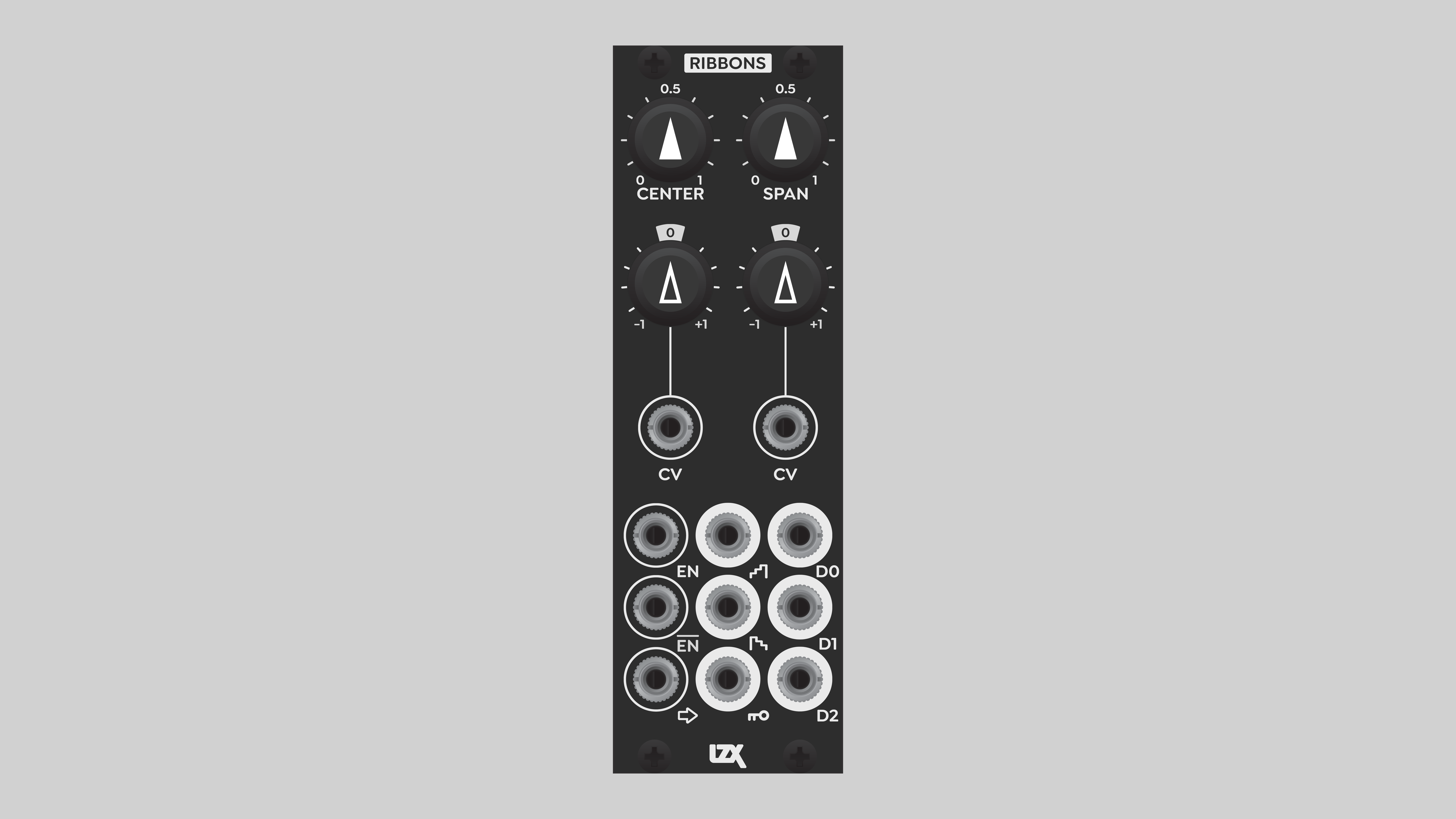
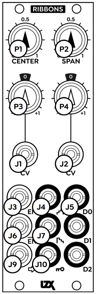
Controls & Connectors
The primary Input to the digitizer is at the extreme lower left. Above that are Enable and Disable inputs. The Enable input is labeled . The Disable input is labeled . The bar over the letters is called a macron, and in this context it indicates logical negation. The input label means "not enable", or disable.
The Enable and Disable inputs are binary. They mask all of the Ribbons outputs. A voltage above 0.5 sent to the Enable input reveals the outputs, a voltage below 0.5 masks off the outputs. The Disable input inverts this behavior: a high signal masks off the outputs, a low signal reveals them. Enable and Disable inputs can be used simultaneously.
Sending a static voltage below 0.5 volts to the Enable input entirely blanks all outputs of Ribbons. Likewise, a static voltage above 0.5 volts at the Disable input also blanks the outputs.
Center and Span potentiometers are at the top of the panel. These define the value ranges of the digitizer. Values within this range are sampled and quantized to one of eight discrete values. Instead of setting the upper and lower bounds directly, we define them with Center and Span. This makes it easy and intuitive to set desired value ranges, even when the source values are constantly changing. Center is the midpoint of values to be digitized, Span is the width of the value range above and below the Center.
In the middle of the module are control voltage inputs to automate or modulate digitizer sampling thresholds. Center CV is on the left, Span CV is on the right. Modulation amount is multiplied by the Center CV Depth and Span CV Depth attenuverter pots, which range from -1 to +1.
At the lower right of the module are the three Digital Outputs. At the top is D0, which is the most significant bit. That's the highest, left-most digit of the three-bit binary number, or the "fours place". D1 is the middle bit, or the "twos place". At the lower right of the module, D2 is the least significant bit. That's the lowest, right-most digit of the three-bit binary number, or the "ones place".
The digitized video within Ribbons is also converted back to analog, available from the DAC output. The eight values are combined to a single signal that can stand alone as an interesting visual effect, be further processed to add color, or quantize a low frequency modulation source to a stair-step pattern. A convenient Inverted DAC output expands patching potential.
A bonus Window Key output sends out a binary signal of all eight bands combined. The value range between the upper and lower comparator thresholds, as set by Center and Span, is output as a binary value of 1, or white. Values above the upper threshold and below the lower threshold are output as a binary value of 0, or black.
Operation
Digital outputs
Ribbons provides numerous ways to use the digitizer circuit. The Digital Outputs are the eponymous "ribbons": three one-bit, potentially overlapping black and white bands. Each value range of the input signal is sampled as a three-bit binary number: eight possible values, 0 to 7 in base 10. The three bits of the binary number are encoded as voltages of zero or one, and sent to the Digital Outputs. The recombination of those three bits restores the eight possible values.
If we use all eight bands, one of them is going to have a value of zero. For a video image, that's black. In the lowest possible value range, no signal is present at any of the Digital Outputs. This means our ability to manipulate that value range is somewhat limited. But we can always set the Center and Span to output fewer bands, cropping out the black part of the image. That gives full control over effects such color scheme.
The Digital Outputs can be sent to other modules for posterization effects. Even just sending them directly to the encoder RGB inputs creates an instant color bars effect from any luminance signal. The Digital Outputs can be combined with each other, or with the DAC outputs, to widen the possible color palettes.
Modulation
The Center CV and Span CV inputs are the not-so-secret weapons of Ribbons. Low frequency signals applied to the CV inputs will dynamically change the comparator thresholds, making the value bands "breathe".
Unique effects result from patching a video image to a CV input. The bands of the primary input shift around based on the values of the CV image. Using different video images for the primary and CV inputs gives a freaky sort of layering that can only be achieved in this way.
Pre-processing
Explore interesting effects by pre-processing the primary source. Applying bias and gain before Ribbons makes the color bands "breathe" in and out in a way different to the Center and Span controls.
An exponential or logarithmic transform via DSG3 changes the width of the bands based on brightness, a common posterization effect.
Frequency multiplication wavefolding with DSG3 or Stairs results in smaller, repeating bands, reminiscent of false color displays for scientific visualization. High frequency wavefolding through Ribbons produces a riot of detail and color.
Integration with Switcher
The control inputs of Switcher work well with the Digital Outputs of Ribbons. And since the Switcher control inputs are video rate, we can plug any sources we wish into the Switcher RGB inputs, and create complex composites of four RGB sources with two of the Ribbons Digital Outputs.
The simplest patch using this concept is a four-level posterizer. Just send the outputs of 2x Matte or Proc to the RGB inputs of Switcher. This provides independent control over all four color bands. And if we patch the third Ribbons Digital Output into the Disable input of Switcher, we can add a fifth, black band to the posterizer.
Video Tutorials
LZX Ribbons 3-Bit Digitizer | Lars Explains
presented by Lars Larsen
Dobbels Demos Ribbons
presented by Andrew Dobbels
Installation
Requirements
- EuroRack enclosure
- 12V DC or EuroRack power supply
- 2.1mm DC barrel power cable or a EuroRack power cable (both options included)
- Four M2.5 x 6mm mounting screws, or screws provided or specified by the enclosure manufacturer
- #1 Phillips head screwdriver, or hand tool provided or specified by the enclosure manufacturer
Procedure
- Power off and disconnect the EuroRack enclosure's power supply and any attached DC adapters.
- Connect either the EuroRack Power Cable or the DC Barrel Power Cable to the module. Do not connect both Eurorack and DC Barrel power.
- Ensure that no mounting screws are in any holes in the area where you wish to mount the module.
- Carefully test fit the module with its attached power cable in the open space in the EuroRack enclosure. If it is obstructed by the enclosure or any internal assemblies, abort this procedure.
- Connect the disconnected end of the power cable to the power supply.
- Mount the module to the EuroRack rails using all mounting holes.
- Store the unused cable along with the product box in a safe location.
- Power on the EuroRack enclosure and start patching.
Full Specifications
| Connectors | Controls | |||||||||||||||||||||||||||||||||||
|---|---|---|---|---|---|---|---|---|---|---|---|---|---|---|---|---|---|---|---|---|---|---|---|---|---|---|---|---|---|---|---|---|---|---|---|---|
 |
|
|
Technical Data
| Parameter | Value |
|---|---|
| Manufacturer Part Number | 950049 |
| Mounting Width | 8 HP |
| Mounting Depth | 32 mm |
| Mounting Hole Count | 4 |
| Power Consumption | 12V @ 125 mA |
| Power Connectors | 16 pin EuroRack ribbon, 2.1mm DC barrel |
| Input Impedance | 1M ohms |
| Output Impedance | 75 ohms |
| Input Protection Range | +/-20V |
| Input Clipping Range | +/-2.5V |
| Output Range | +/-2.5V |
| Included | DC barrel power cable, EuroRack power cable |
| EuroRack Power Cable Type | 16-pin |
| EuroRack Power Cable Length | 25 cm |
| DC Barrel Power Cable Length | 25 cm |
| RoHS Compliance | Manufactured with lead-free processes |
| Video Sync | None |
Maintenance
Keep the module free of dust and debris by performing periodic cleaning. Spots may be cleaned from the front panel with a microfiber cloth and isopropyl alcohol or other electronics cleaner.
Hardware Revisions
The hardware revision code is printed on the circuit board visible from the rear of the module.