DWO3
Overview
Capable of an exceptionally wide range of frequencies and precision modulation, DWO3 is the most advanced analog video oscillator available. It's capable of generating high frequency waveforms for SD and HD video pattern generation, or low frequencies for animation control. High frequency oscillation modes can run freely, or lock to incoming video sync.
DWO3 features two independent oscillators, each with four different simultaneous waveform outputs. Each oscillator can be frequency modulated with a linear input, an exponential input with an attenuverter, or both. A gate supplied to the Reset input blanks off the oscillator output and resets the phase, starting a new cycle.
Features:
- Two discrete voltage-controlled oscillators
- Four waveforms: sine, square, sawtooth, and triangle
- Eight frequency ranges, from several seconds to 2 MHz
- Extended low frequency range of ~5 minutes per cycle with CV input
- Linear and Exponential frequency modulation CV inputs
- Exponential modulation CV Depth control with 100:1 tuning ratio
- Frequency fine tuning with CV Depth, even with no signal patched in
- Reset inputs for oscillator output gate and cycle phase reset
Key Specifications
| Mounting Width | 12 HP |
| Power Consumption | 12V @ 230 mA |
| Power Connectors | 16 pin EuroRack ribbon, 2.1mm DC barrel |
| Included | DC barrel power cable, EuroRack power cable, RCA sync cable |
| Video Sync | Rear RCA in & out |
System Integration Advice
Oscillators are essential components of any video synthesizer. The wide frequency range of DWO3 allows each oscillator to generate a video pattern or a low frequency animation control voltage. It's the most versatile option available.
The compact form factor and versatility of DWO3 facilitates the configuration of modular synths with many oscillators that can serve multiple functions. For example, two DWO3 modules take up 24 HP, and can be dynamically patched to serve as any combination of four horizontal, vertical, or low frequency oscillators. One DWO3 can serve as a horizontal and vertical pattern generator, and the other can provide animation modulation.
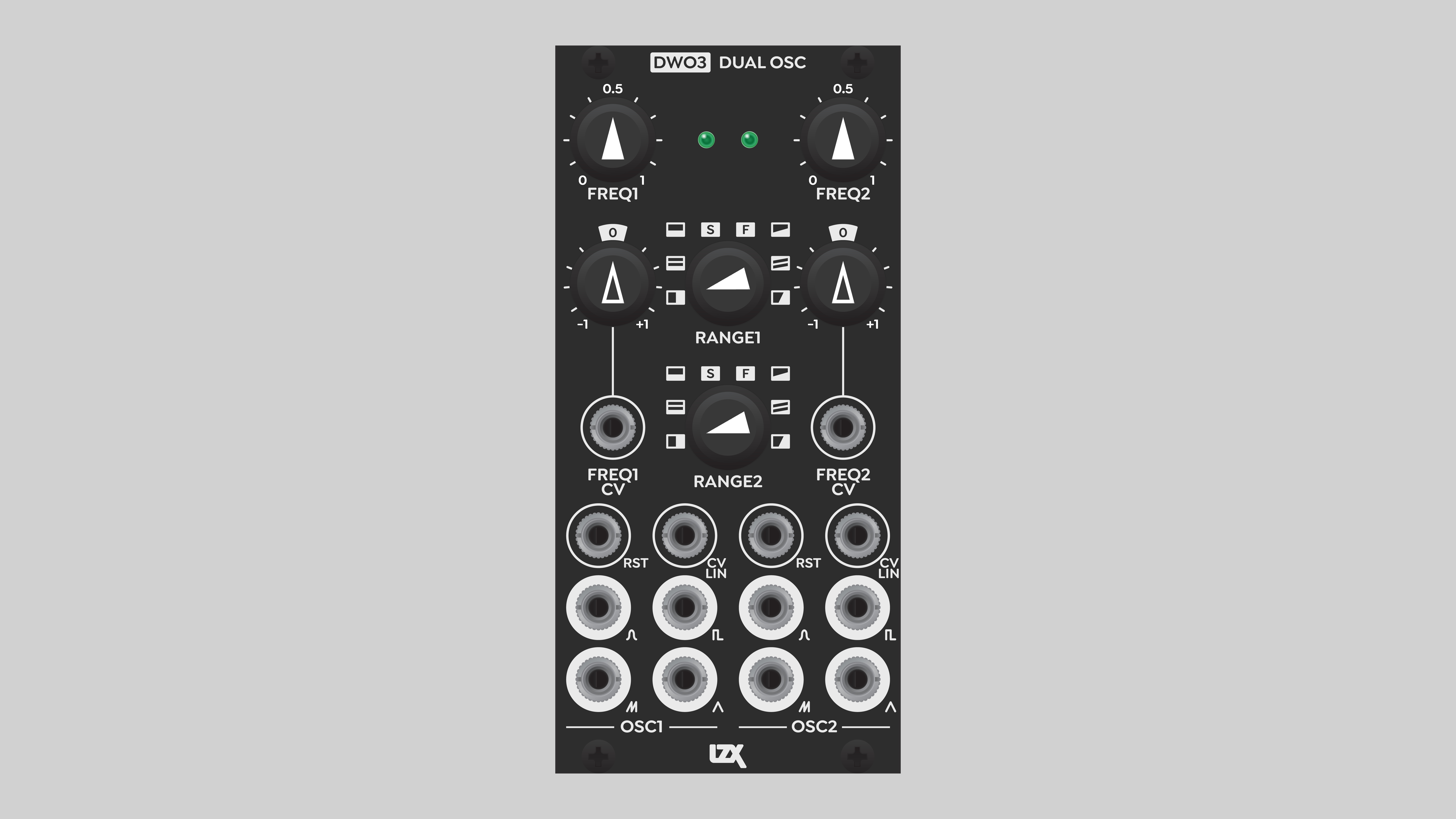
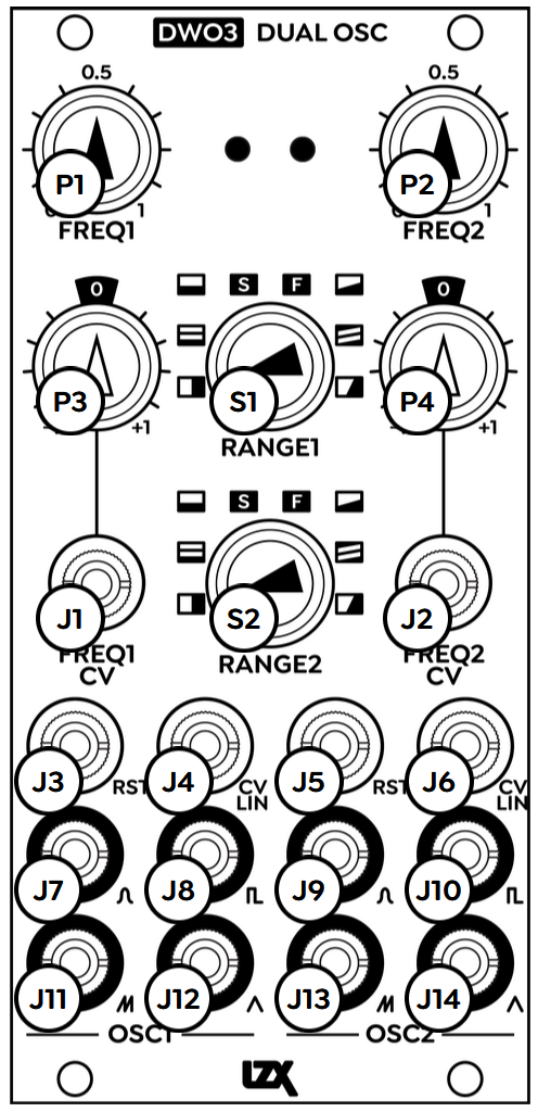
Controls, Connectors & Indicators
DWO3 is divided into two identical submodules, labeled OSC1 and OSC2. Inputs and outputs of OSC1 are on the left, inputs and outputs of OSC are on the right.
At the top of each submodule, the base frequency of the oscillator is adjusted via the potentiometer labeled FREQ.
The frequency range for each oscillator is set with an eight-position rotary switch in the center of the module, labeled RANGE. Oscillator 1 range is on top, Oscillator 2 range is below.
Four simultaneous waveform outputs are available at the bottom of each submodule. All outputs of a single oscillator are at the same phase-aligned frequency. The waveforms are Sine, Square, rising Sawtooth, and Triangle.
Inputs
Directly above the oscillator outputs are two input jacks, labeled RST and CV LIN. As with all control voltage inputs on Gen3 modules, these can accept video rate signals. The Reset input accepts a gate that can blank the oscillator output, or reset the phase of the oscillator. The Linear CV input accepts a continuous signal that directly frequency modulates the oscillator, without any depth control.
Above the RST and CV LIN inputs is the exponentially controlled frequency modulation input jack, labeled FREQ CV. A signal supplied to this input is multiplied by the potentiometer directly above it, the Frequency CV Depth. This pot is an attenuverter, providing exponential control over the modulation amount. Turning the knob away from center increases the modulation amount exponentially, with a range of 100:1. With an incoming positive voltage, clockwise rotation increases the oscillator frequency. Counter-clockwise rotation inverts the modulation, decreasing the oscillator frequency.
In the absence of an incoming modulation signal, the Freq CV pot works as a fine tuner for the oscillator frequency. A static voltage of 0.1 v is normalled into the Frequency CV input.
LEDs
Phase of the oscillator is indicated by the LED lights at the top of the module. Each oscillator starts at a value of zero and rises over time. Low values are indicated by a green light, and high values are indicated by a red light. At high frequencies, the LED displays different colors depending on the average value of the output at the current time. In most cases, that results in a yellow or amber light. However, even at high frequencies, some settings can result in an output of zero across the entire frame, resulting in a green light. Likewise, when the output is blanked off by a Reset gate, the LED displays green.
Operation
Frequency range
The most basic control on DWO3 is the frequency range. The options, from left to right, are:
- Locked Horizontal
- Horizontal video frequencies, locked to sync
- Locked Upper Vertical
- Vertical video frequencies, locked to sync, higher range
- Locked Lower Vertical
- Vertical video frequencies, locked to sync, lower range
- Seconds
- Lowest frequencies, down to approximately one cycle per five seconds
- Extended CV low frequency down to approximately one cycle per five minutes
- Frames
- Range from approximately 2 Hz up to vertical video frequencies
- Free Lower Vertical
- Vertical video frequencies, free-running, lower range
- Free Upper Vertical
- Vertical video frequencies, free-running, upper range
- Free Horizontal
- Horizontal video frequencies, free-running
Vertical frequency ranges produce horizontal bands, from side to side. Horizontal frequency ranges produce vertical bands, from top to bottom. The horizontal frequency range is the highest.
To extend the low frequency range, supply a positive static voltage to the Freq CV input. Set the Freq CV knob counterclockwise to invert the incoming signal. (You can also use a negative static voltage, and set the Freq CV knob clockwise.) With this technique, you can get a frequency as slow as once cycle every five minutes.
The frequency ranges overlap with one another. For example, a high knob setting in the Frames range will produce a result similar to a lower knob setting in the Free Lower Vertical range. This is by design, to enable creative freedom in frequency modulation. If the ranges did not overlap, transitions between particular frequencies might not be possible.
Especially in high definition formats, it's normal to see some amount of noise in the highest frequency ranges, above the horizontal frequency of video. The cleanest output is achieved with barrel power instead of Eurorack ribbon power. Most Eurorack power supplies weren't designed for such high frequencies, and our perception is much more sensitive to visual noise than to auditory noise.
Reset
A positive gate supplied to the RST jack blanks the output of the oscillator. When the gate returns to zero, the phase is reset. The oscillation resumes, starting from a phase of zero, which is also a value of zero.
Some combinations of base/carrier frequency and Reset gate frequency will result in a constant output of zero volts.
Just as with frequency modulation, if the frequencies of the base/carrier wave and the Reset gate are similar, the visual result will be "beating", or patterns of interference. This is one way to add variable width to visual elements.
Video Tutorial
3 Patches for DWO3
presented by Johnny Woods
Installation
Requirements
- EuroRack enclosure
- 12V DC or EuroRack power supply
- 2.1mm DC barrel power cable or a EuroRack power cable (both options included)
- Four M2.5 x 6mm mounting screws, or screws provided or specified by the enclosure manufacturer
- #1 Phillips head screwdriver, or hand tool provided or specified by the enclosure manufacturer
Procedure
- Power off and disconnect the EuroRack enclosure's power supply and any attached DC adapters.
- Connect either the EuroRack Power Cable or the DC Barrel Power Cable to the module. Do not connect both Eurorack and DC Barrel power.
- Ensure that no mounting screws are in any holes in the area where you wish to mount the module.
- Carefully test fit the module with its attached power cable in the open space in the EuroRack enclosure. If it is obstructed by the enclosure or any internal assemblies, abort this procedure.
- Connect the disconnected end of the power cable to the power supply.
- Connect the sync cable to a sync source, such as a sync DA or the last module in the sync chain.
- Mount the module to the EuroRack rails using all mounting holes.
- Store the unused cable along with the product box in a safe location.
- Power on the EuroRack enclosure and start patching.
Full Specifications
| Connectors | Controls | |||||||||||||||||||||||||||||||||||||||||||||||
|---|---|---|---|---|---|---|---|---|---|---|---|---|---|---|---|---|---|---|---|---|---|---|---|---|---|---|---|---|---|---|---|---|---|---|---|---|---|---|---|---|---|---|---|---|---|---|---|---|
 |
|
|
Technical Data
| Manufacturer Part Number | 950040 |
| Mounting Width | 12 HP |
| Mounting Depth | 42 mm |
| Mounting Hole Count | 4 |
| Power Consumption | 12V @ 230 mA |
| Power Connectors | 16 pin EuroRack ribbon, 2.1mm DC barrel |
| Input Impedance | 1M ohms |
| Output Impedance | 75 ohms |
| Input Protection Range | +/-20V |
| Input Clipping Range | +/-2.5V |
| Output Range | +/-2.5V |
| Included | DC barrel power cable, EuroRack power cable, RCA sync cable |
| EuroRack Power Cable Type | 16-pin |
| EuroRack Power Cable Length | 25 cm |
| DC Barrel Power Cable Length | 25 cm |
| RoHS Compliance | Manufactured with lead-free processes. |
| Video Sync | Rear RCA in & out |
Calibration
DWO3 may require calibration from time to time to ensure symmetrical waveforms.
At the bottom rear of the module is a row of ten trim potentiometers, in two pairs of five. The five trim pots for each oscillator are physically located on the same side as the corresponding oscillator controls. As seen from the rear, the right side of the module is Oscillator 1, and the left side is Oscillator 2.
Trim pots are labeled with a suffix 1 or 2 to indicate which oscillator they adjust. From center to edge, the trim pots are:
- R35: Sawtooth Bias
- R33: Sawtooth Amplitude
- R39: Sine Shaper Pre-bias
- R37: Sine Shaper Pre-amplitude
- R50: Sine shaper Post-bias
Calibration requirements
- Power source
- Sync source
- Oscilloscope
- Adapter cable: male mini plug to male BNC plug
- Trim adjustment tool or jeweler's screwdriver
- Magnifying lens (if needed)
Calibration procedure
- Power down the system and unmount the module if needed.
- Connect power and sync to module.
- Power up the system.
Sawtooth calibration
- Connect Sawtooth output to oscilloscope.
- Set oscillator frequency range to Locked Horizontal (highest rate).
- Set oscillator frequency knob to approximately ten o'clock.
- Set vertical range of oscilloscope to fully visualize a signal between zero and one volts.
- Set scanning activation threshold of oscilloscope ("trigger") to approximately 0.25 volts, or whatever value between zero and one volt that yields a stable display. It may be necessary to adjust the threshold throughout the calibration process.
- Set horizontal range of oscilloscope to view approximately three cycles. In Locked Horizontal mode, the oscillator output goes negative at the start of each line. Set the oscilloscope to view about three lines of video. You should see the oscillator output go below zero three times. Between each of those negative values, you should see approximately five sawtooth ramps ranging from approximately zero to one volt.
- If necessary for visualization of the sawtooth wave, use Freq CV Depth knob to fine-tune oscillator frequency.
- Adjust R35 Sawtooth Bias and R33 Sawtooth Amplitude to achieve a symmetrical sawtooth wave ranging from zero to one volts. These adjustments affect one another, so you'll need to go back and forth between them several times to calibrate the Sawtooth wave.
- To verify the shape of the waveform, check it in various oscillator frequency ranges and oscilloscope horizontal ranges.
Sine calibration
- Connect Sine output to oscilloscope.
- Set oscillator frequency range to Locked Horizontal (highest rate).
- If necessary for visualization of the sine wave, adjust Freq CV Depth knob to fine-tune oscillator frequency, and/or adjust oscilloscope activation threshold.
- Adjust R39 Sine Shaper Pre-bias, R37 Sine Shaper Pre-amplitude, and R50 Sine shaper Post-bias to achieve a symmetrical sine wave ranging from zero to one volts. These adjustments affect one another, so you'll need to go back and forth between them several times to calibrate the Sine wave.
- To verify the shape of the waveform, check it in various oscillator frequency ranges and oscilloscope horizontal ranges.
Maintenance
Keep your module free of dust and debris by performing periodic cleaning. Spots may be cleaned from the frontpanel with a microfiber cloth and isopropyl alcohol or other electronics cleaner.
Hardware Revisions
The hardware revision code is printed on the circuit board visible from the rear of the module.