Contour
Overview
Contour is a triple voltage-controlled high-pass filter for extracting edge transitions from video images and patterns. Its analog circuitry imparts unique qualities to the picture. From glitchy streaks to spectral afterimages, Contour produces effects that exemplify the art form of video synthesis. These are exactly the sorts of effects that set analog video synthesis apart from the technically perfect but sometimes stilted visual language of digital video. In contrast to the antiseptic, sterile quality that often renders digital video less than compelling, the otherworldly strangeness of Contour can only come from the messy and unpredictable processes of analog video synthesis.
Key Specifications
| Mounting Width | 8 HP |
| Power Consumption | 12V @ 110 mA |
| Power Connectors | 16 pin EuroRack ribbon, 2.1mm DC barrel |
| Included | DC barrel power cable, EuroRack power cable |
| Video Sync | None |
System Integration Advice
All by itself, Contour can add analog weirdness to any monochrome or color video signal. To get the most out of Contour, support modules such as Proc and SMX3 come in very handy. Amplifying a signal before it reaches Contour gives its high pass filter more dynamic range to work with.
Controls & Connectors
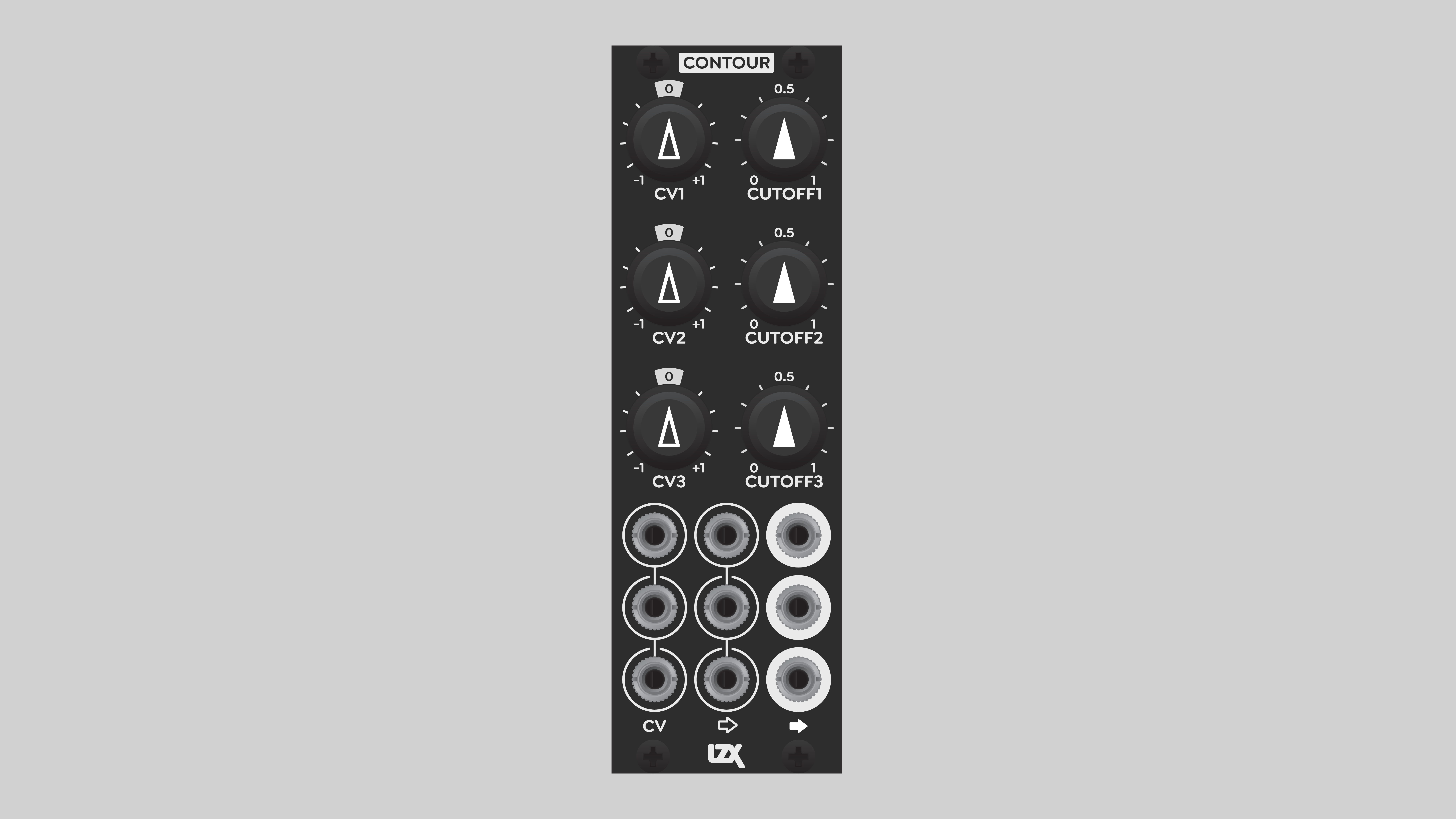
Contour is divided into three identical channels. Each has a Filter Output on the right, a Filter Input in the center, and a Cutoff CV input on the left. The Cutoff CV input allows external modulation of the filter cutoff threshold. As always in Gen3 modules, the inputs are internally self-normalled, so that a signal flows from a patched input to the unpatched inputs below it.
Each channel has two potentiometers. The Cutoff knobs to the right set the frequency threshold for the high-pass filter. Turning the knob to the right increases the Cutoff, filtering out more of the low frequency components of the signal. The visual effect of a high Cutoff is an image that's mostly black except for the edges. Reducing the Cutoff allows more of the original image to pass through the filter, revealing more of the larger compositional elements, and often smearing them to the right of the screen in a unique way.
The Cutoff CV Depth knobs on the left are attenuverters that multiply the incoming Cutoff CV signal before it's added to the filter Cutoff frequency. At the center position, the Cutoff CV input is disabled. When the knob is turned clockwise, to the right, a positive Cutoff CV voltage increases the Cutoff frequency. When turned counterclocwise, to the left, a positive Cutoff CV decreases the Cutoff frequency.
Again, as always in Gen3 modules, the CV inputs can accept video rate signals. This means we can use an image or pattern to alter the Cutoff frequency, for an extra dimension of visual weirdness.
Operation
Frequency
The key to understanding Contour is that it is all about frequency, which manifests as the rate of change or fine details of an image. How fast the image changes across a horizontal line is an objective measure of the amount of detail. If the changes are very fast, we'll see small features and a lot of detail. If the changes are slow, the result is larger compositional elements and less detail.
As a high-pass filter, Contour removes the lower frequency components of the video image, allowing the high frequency details to pass through. At its maximum Cutoff frequency, Contour eliminates almost all low frequency components. Gradients are eliminated, and render as black at the Filter Outputs.
Contour can only affect the horizontal axis of an image, it has no impact on the vertical axis. Due to the inherent geometry of the video raster, high frequency analog filters are only effective on transitions in the horizontal dimension. Affecting the picture in the vertical dimension, between adjacent scanlines, requires a digital frame buffer.
The frequency range of Contour is fixed, but the frequency ranges of various video standards are different. Contour will give different results depending on the video format. For example, at the highest Cutoff frequency, the output of Contour may appear sharper in SD than in HD. High definition formats run at higher frequencies, so less of the image can be filtered out.
Bias and polarity
Because Contour operates on frequencies, it really only looks at the differences in the signal gain over time. The overall bias, DC offset, or pedestal of the signal is not that important. If you bias a signal before it goes into Contour, you may see little or no effect. That's just the way the high pass filter circuit works. You'll only see any effect of biasing if some part of the signal goes above or below the range of approximately +/- 2.5 volts. In that case, some value range will be clipped, and some image details lost.
Contour can accept bipolar signals, but its output is always unipolar. The fact that it can accept a bipolar signal without clipping might seem to indicate that it would work fine with the I and Q components of Swatch. But in practice, that doesn't work because I and Q are lower frequency signals than Y, R, G, or B. Almost all of the detail in a YIQ triplet is in the Y component. There isn't enough high frequency detail in I and Q to begin with. The Cutoff threshold of Contour will remove so much of I and Q that there is almost nothing left. However, running Y through Contour, and leaving I and Q alone, or processing them separately, might be an interesting visual effect.
Amplitude
Parts of the image that are filtered out by Contour are entirely removed. They render as black. Frequencies above the cutoff range are allowed through the circuit. But the Cutoff threshold is not absolutely sharp or instantaneous. It has some slope to it. Frequencies within a narrow range around the Cutoff will be removed entirely, attenuated somewhat, or allowed to pass through at full amplitude.
The net result of this for image manipulation is that the output of Contour may appear dim or lacking contrast. The high frequency edges are there, but they may be at lower values than the incoming signal. To compensate for this, we can amplify the source going into Contour, amplify the output of Contour, or both.
Cranking up the source amplitude provides a wider dynamic range for Contour to work with, resulting in better contrast at the output. The attenuation of some frequencies near the Cutoff is compensated by the greater input amplitude. The input range of Gen3 modules is approximately +/- 2.5 volts before distortion occurs. That's the optimal input range of Contour. For an RGB triplet, we can achieve a +/- 2v range with SMX3, a 1v static voltage source such as Proc, Matte or PGO, and three passive mults. Send each source RGB component to two inputs on a single row of SMX3. Send a 1v signal into the top input of the third column of SMX. Turn the RGB input pots up to 2x, and the static voltage input pots down to -2x.
Alternately, we can amplify the output of Contour. This is a simpler patch, but may sacrifice some detail.
Video Tutorial
3 Patches for Contour
presented by Johnny Woods
Installation
Requirements
- EuroRack enclosure
- 12V DC or EuroRack power supply
- 2.1mm DC barrel power cable or a EuroRack power cable (both options included)
- Four M2.5 x 6mm mounting screws, or screws provided or specified by the enclosure manufacturer
- #1 Phillips head screwdriver, or hand tool provided or specified by the enclosure manufacturer
Procedure
- Power off and disconnect the EuroRack enclosure's power supply and any attached DC adapters.
- Connect either the EuroRack Power Cable or the DC Barrel Power Cable to the module. Do not connect both Eurorack and DC Barrel power.
- Ensure that no mounting screws are in any holes in the area where you wish to mount the module.
- Carefully test fit the module with its attached power cable in the open space in the EuroRack enclosure. If it is obstructed by the enclosure or any internal assemblies, abort this procedure.
- Connect the disconnected end of the power cable to the power supply.
- Mount the module to the EuroRack rails using all mounting holes.
- Store the unused cable along with the product box in a safe location.
- Power on the EuroRack enclosure and start patching.
Full Specifications
| Connectors | Controls | |||||||||||||||||||||||||||||||||||
|---|---|---|---|---|---|---|---|---|---|---|---|---|---|---|---|---|---|---|---|---|---|---|---|---|---|---|---|---|---|---|---|---|---|---|---|---|
 |
|
|
Technical Data
| Manufacturer Part Number | 950037 |
| Mounting Depth | 32 mm |
| Mounting Hole Count | 4 |
| Power Consumption | 12V @ 110 mA |
| Power Connectors | 16 pin EuroRack ribbon, 2.1mm DC barrel |
| Input Impedance | 1M ohms |
| Output Impedance | 75 ohms |
| Input Protection Range | +/-20V |
| Input Clipping Range | +/-2.5V |
| Output Range | +/-2.5V |
| Included | DC barrel power cable, EuroRack power cable |
| EuroRack Power Cable Type | 16-pin |
| EuroRack Power Cable Length | 25 cm |
| DC Barrel Power Cable Length | 25 cm |
| RoHS Compliance | Manufactured with lead-free processes. |
| Video Sync | None |
Maintenance
Keep your module free of dust and debris by performing periodic cleaning. Spots may be cleaned from the frontpanel with a microfiber cloth and isopropyl alcohol or other electronics cleaner.
Hardware Revisions
The hardware revision code is printed on the circuit board visible from the rear of the module.