DSG3
Overview
DSG3 is a versatile multi-function generator optimized for creating 2D shapes. Its powerful waveshaping, blending, and logic functions can be applied to external signals or to video ramps generated within DSG3. It can create complex effects, adding great visual interest to patterns and images.
As a standalone pattern generator, DSG3 can output two independent quadrilateral figures. It's also indispensible for more interesting pattern generation patches. As a video processor, DSG3 can manipulate and blend images. Video and low frequency signals such as LFOs can be combined to animate images and patterns in weird and wonderful ways.
Functions
- Invert
- unipolar "negative", output 0 to +1 volt
- Single Fold
- rectify, double frequency, solarize
- Double Fold
- multiply frequency by four, solarize
- Logarithmic curve
- brighten, reduce contrast, gamma 2.0
- Exponential curve
- darken, increase contrast, gamma 0.5
- Average
- weighted sum of two signals
- Minimum
- lower value of two signals (analog logic AND)
- Maximum
- higher value of two signals (analog logic OR)
- Absolute
- difference between two signals (analog logic XOR)
Legacy
DSG3 remixes and augments past designs such as Arch. On deeper investigation, DSG3 is revealed as an innovative design. The internal ramps make it a new animal, a shape generator. Multiple cascading processing functions save space and clean up a patch. The high performance toggle switches are a big improvement for user experience, making it quick and easy to try out various combinations of functions.
Key Specifications
| Mounting Width | 12 HP |
| Power Consumption | 12V @ 350 mA |
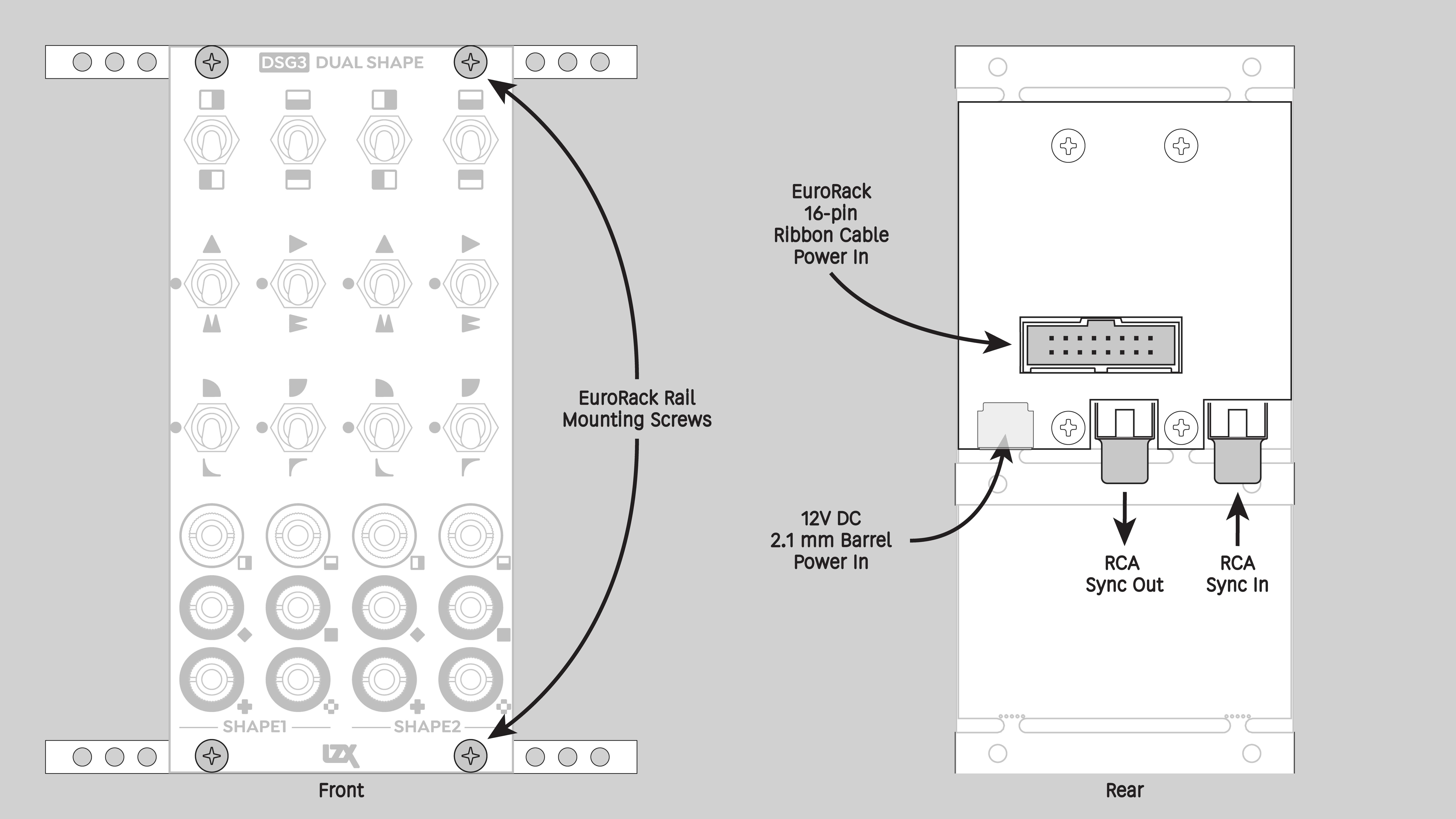
| Power Connectors | 16 pin EuroRack ribbon, 2.1mm DC barrel |
| Included | DC barrel power cable, EuroRack power cable, RCA sync cable |
| Video Sync | Rear RCA in & out |
System Integration Advice
DSG3 is a core module for almost any LZX-compatible system. For 2D pattern generation, DSG3 is essential for symmetry, curvature, and complexity. The inclusion of internal ramps makes DSG3 a full-featured pattern generator. It packs many layers of functionality into a 12HP module, which is particularly important for smaller modular systems.
Likewise, DSG3 is a highly space-efficient general purpose video processor, ideally suited for a wide range of image manipulation and image blending operations.
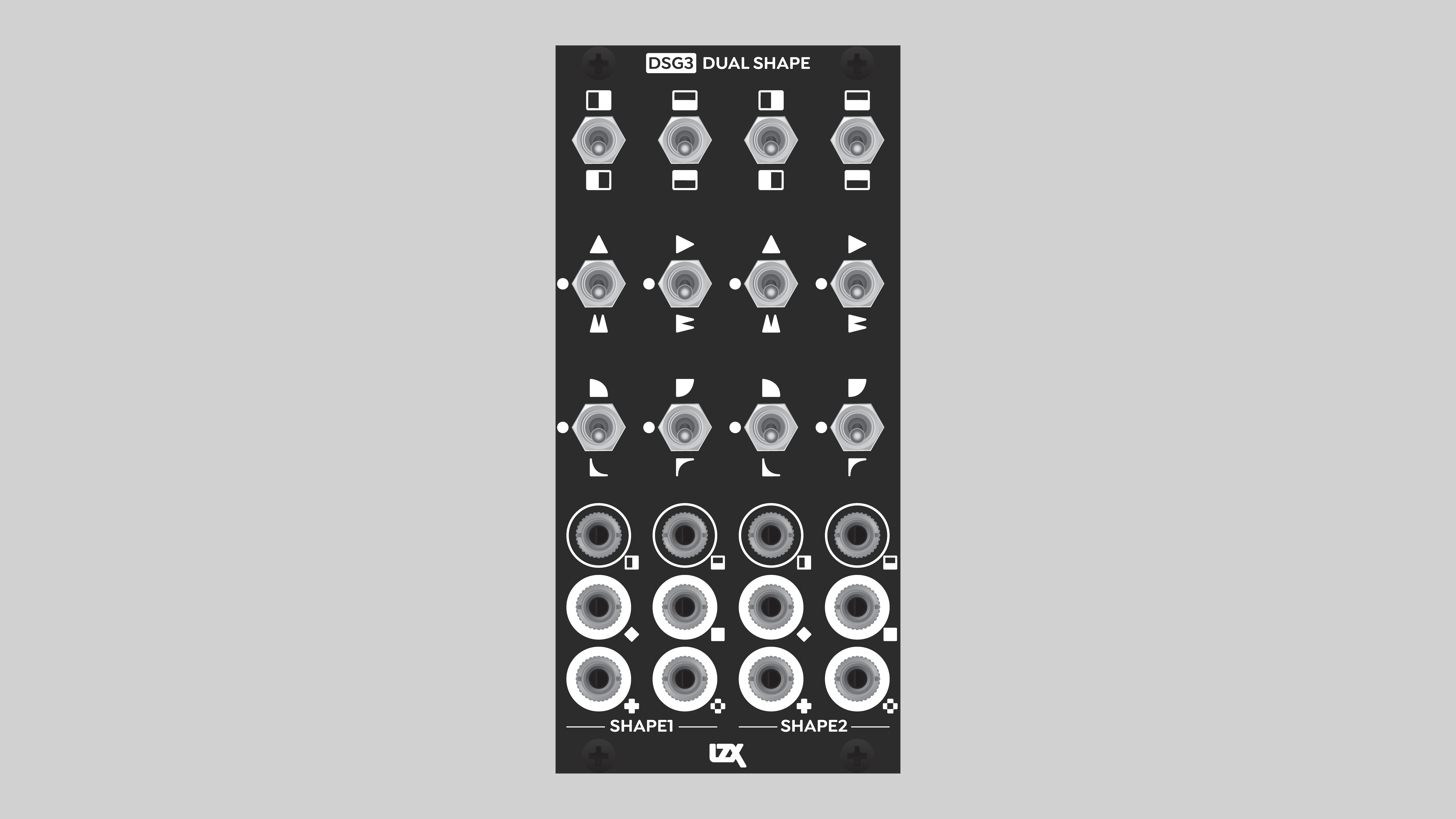
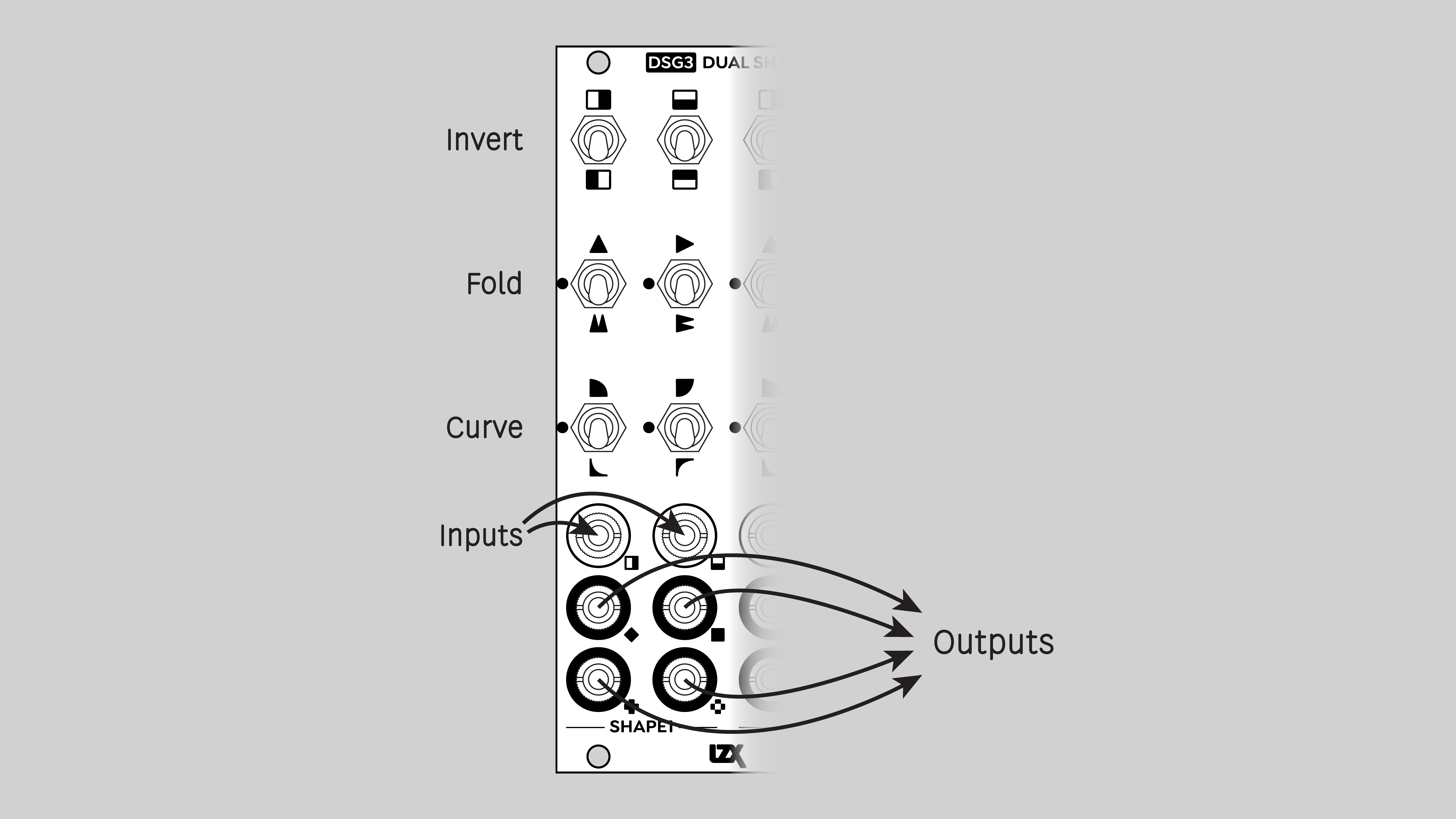
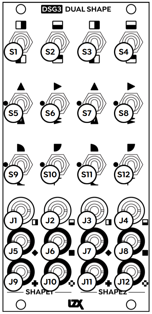
Controls & Connectors
DSG3 consists of two identical submodules, Shape 1 and Shape 2. Each Shape has two inputs, H and V, and four outputs: Average, Minimum, Maximum, and Absolute. Toggle switches enable the various functions: Invert, Fold, and Curve.
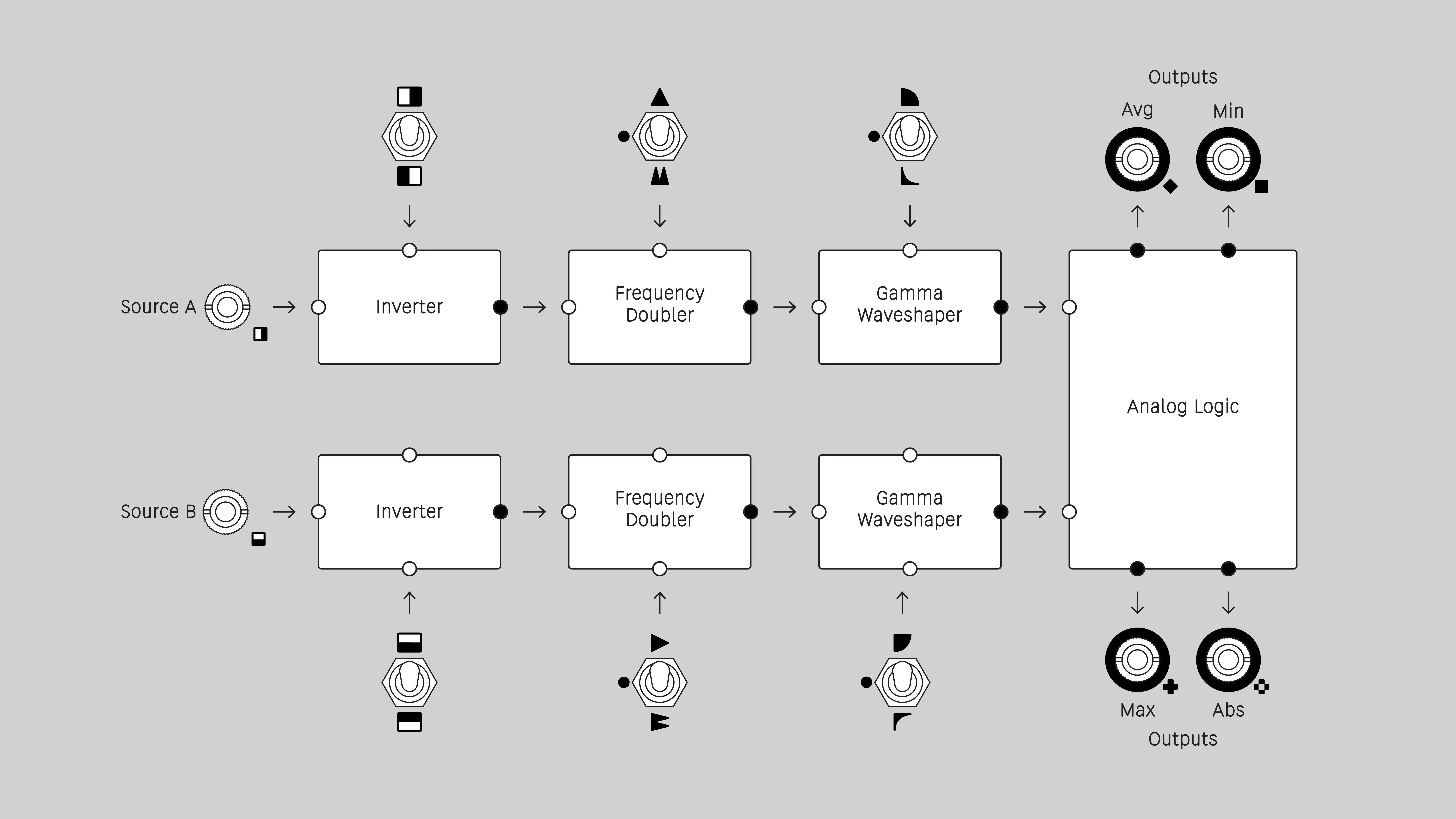
Function block diagram
Operation
Inputs
Each input provides a signal to an identical chain of function blocks. The inputs are referred to as H and V, because horizontal and vertical ramps are internally normalled to the inputs. If nothing is patched to an input jack, then an internal H or V ramp provides the signal to the function block chain.
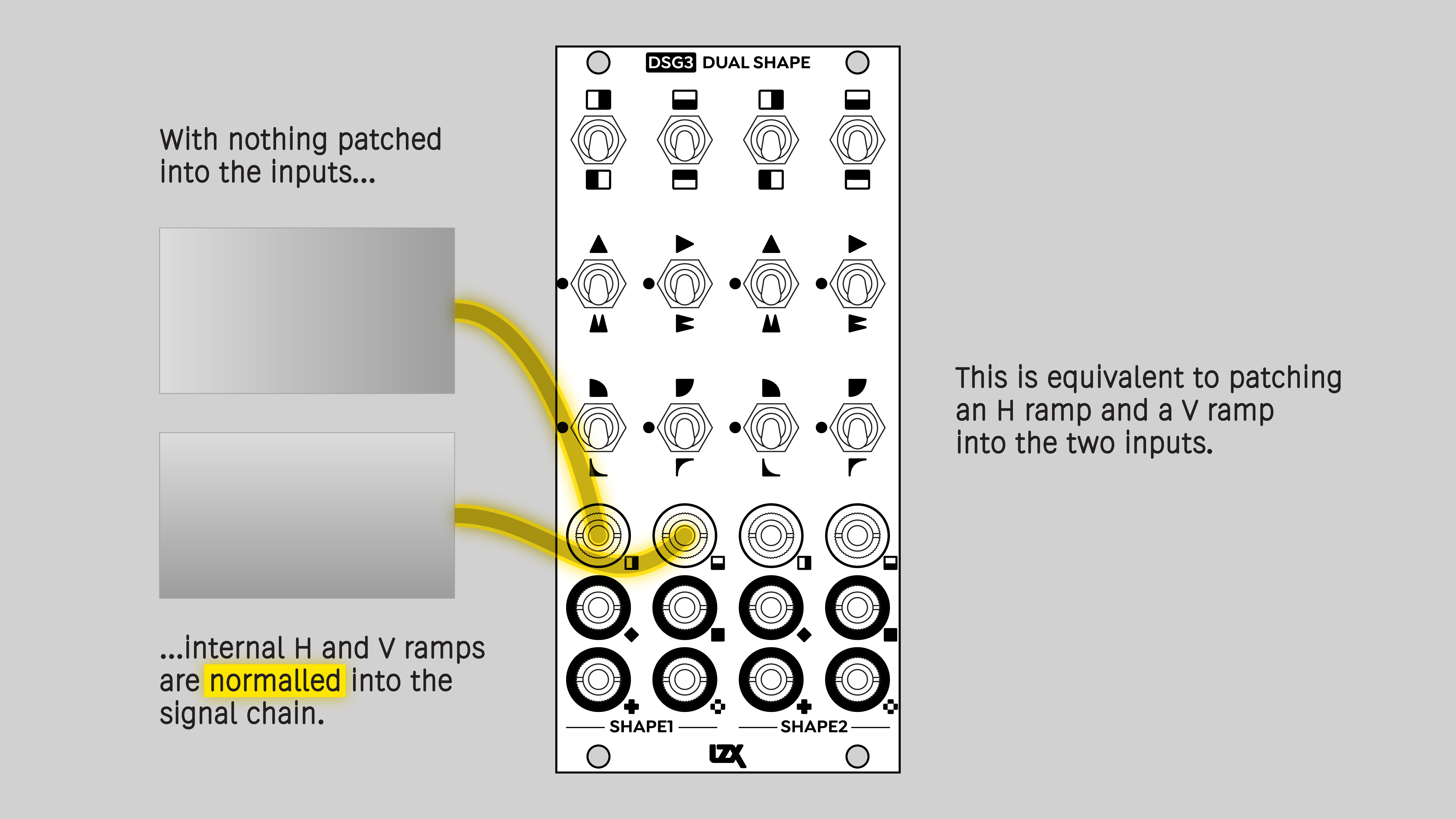
Normalled H and V ramps
DSG3 can accept both positive and negative voltages. This allows for an even wider range of creative effects! The SUM, MIN, and MAX outputs can send positive and negative voltages, but the ABS output is always positive. Some modules, such as encoders, will ignore anything outside the positive unipolar range of zero to +1 volts.
Outputs
Each Shape submodule has four outputs. Each output combines the results of the H and V function block chains. These are sometimes referred to as analog logic due to their similarity to logical functions such as XOR. Unlike Boolean logic, analog logic operates on continuously variable values in addition to binary on/off values.
Each output provides a different blending operation. Average, Minimum, Maximum, and Absolute outputs roughly correspond to the Photoshop blend modes of Add, Minimum, Maximum, and Difference.
To output a single function block chain, without any blending, disable one of the self-normalled ramps. Patch a dummy plug or zero voltage source into one of the inputs. To fully interrupt the normalling, the tip of the dummy plug must be connected to the sleeve.
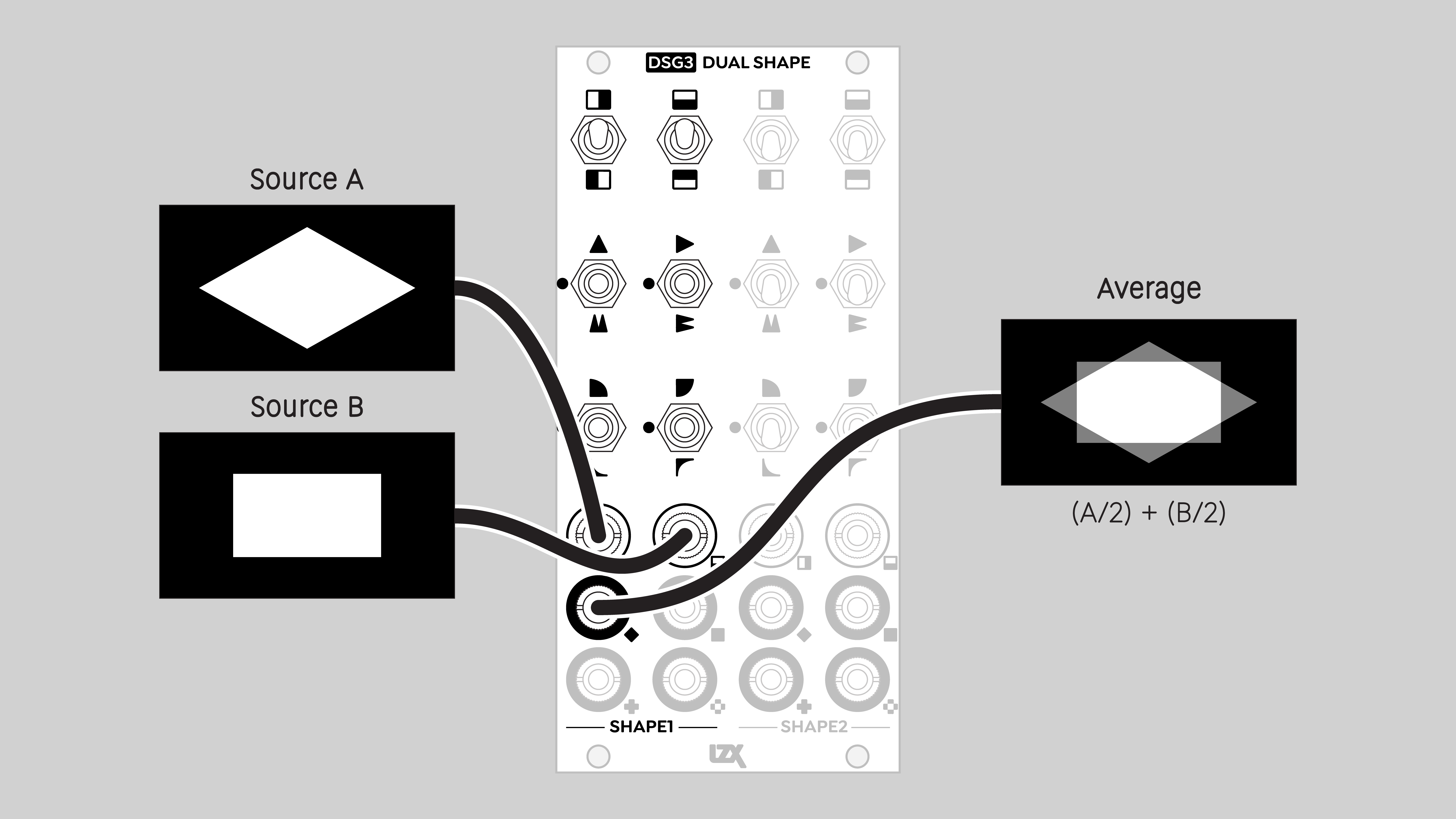
Average
The weighted sum of two input values.
H and V inputs are each divided by two, and the results are summed.
Blend mode: Add
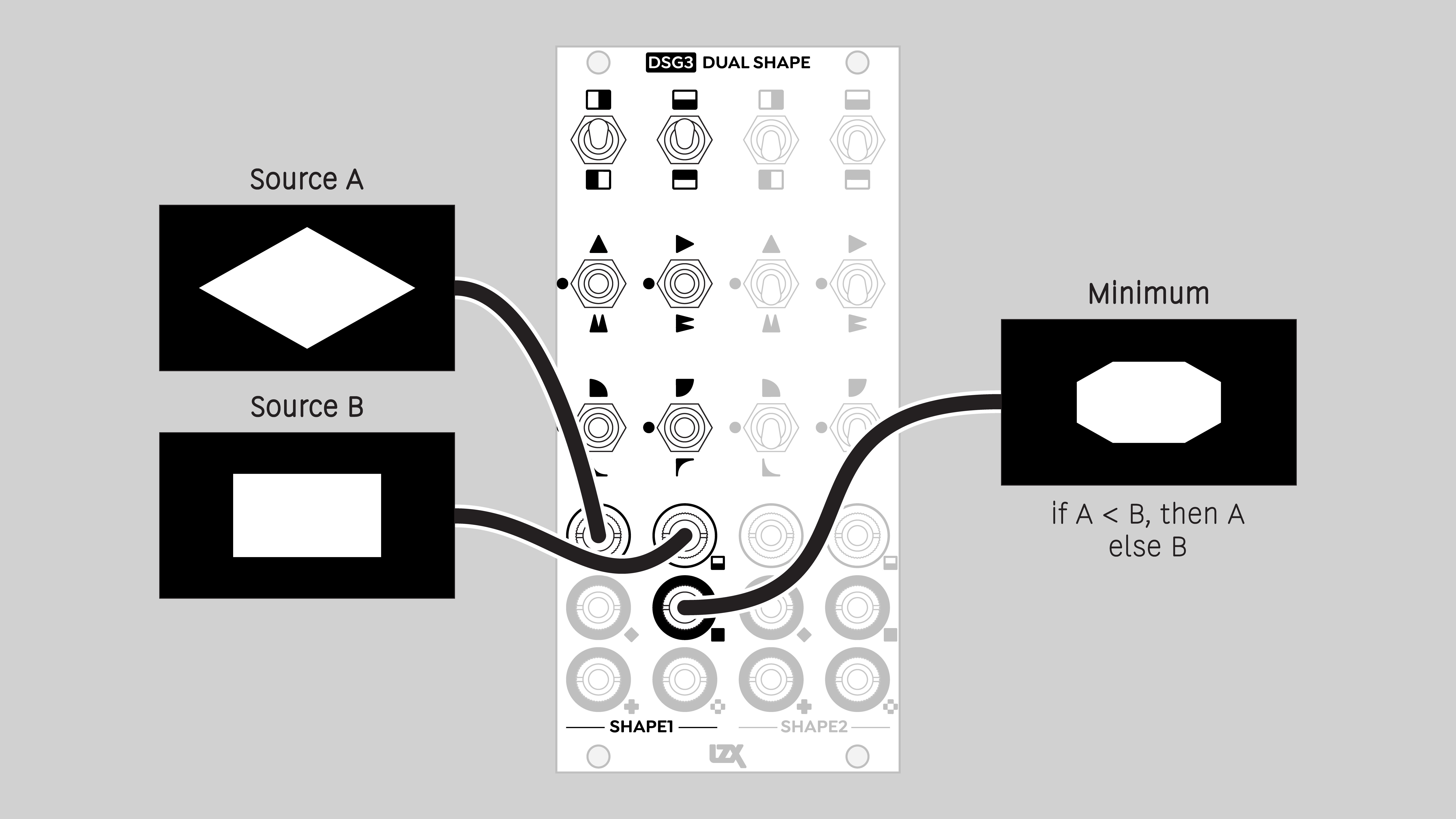
Minimum
The lower of two input values. Corresponds to a logical AND operation.
An output value can only be high if H and V inputs are high.
Blend mode: Minimum
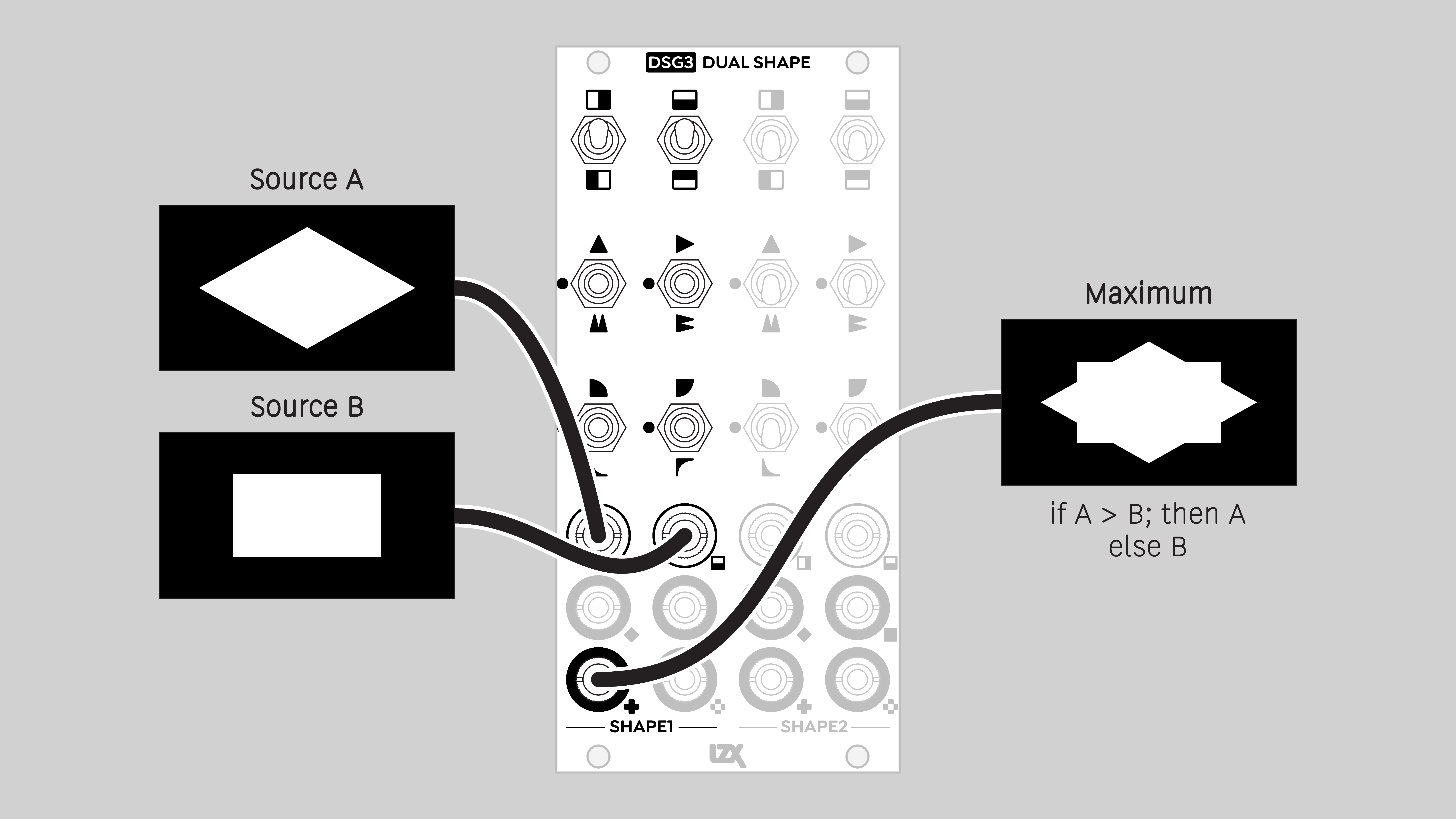
Maximum
The higher of two input values. Corresponds to a logical OR operation.
An output value will be high if either H or V inputs is high.
Blend mode: Maximum
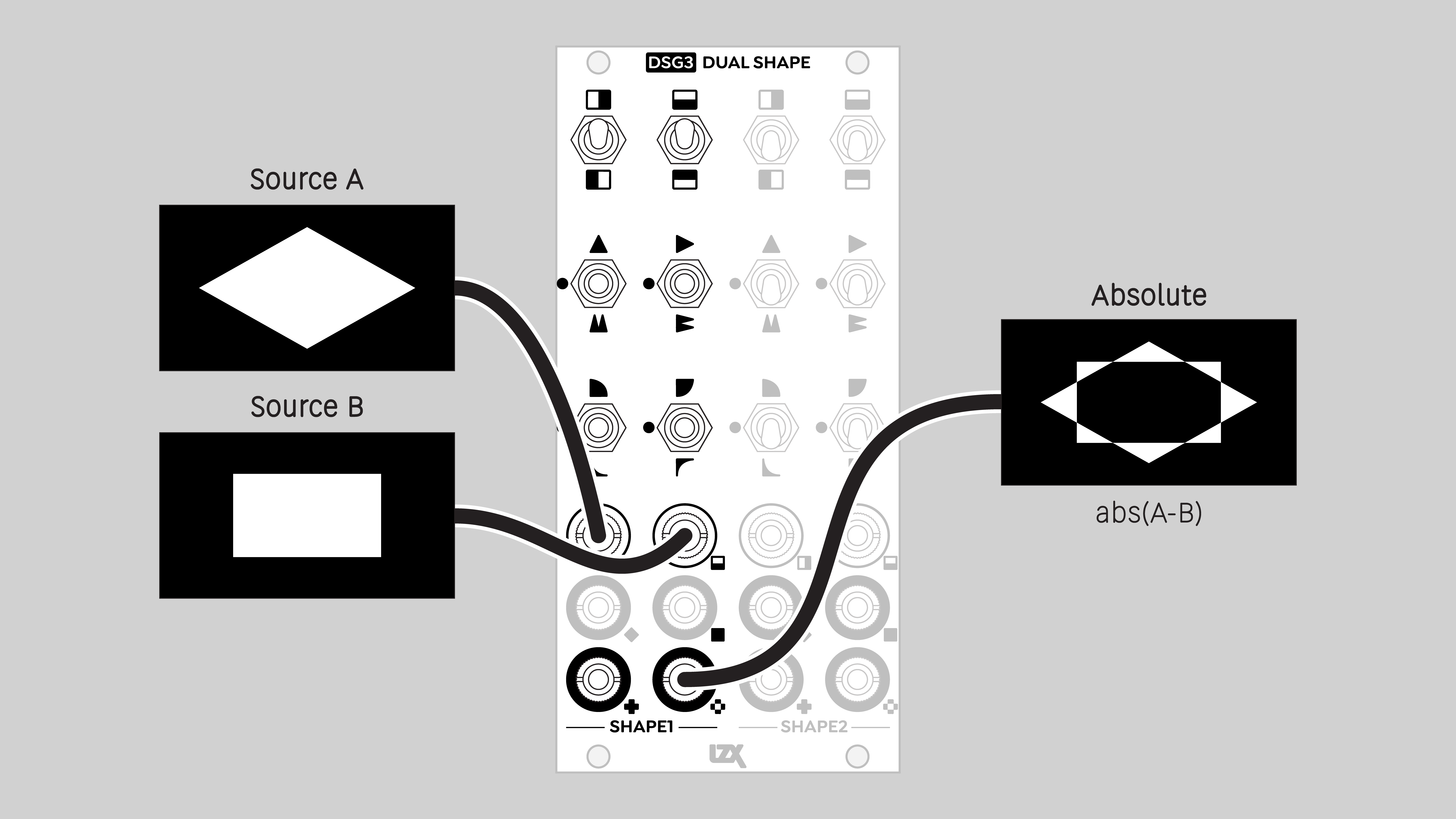
Absolute
The absolute value of the difference between two input values. Corresponds to a logical XOR operation.
An output value will be high if the difference between H and V inputs is large. An output value will be low if the difference is small.
Blend mode: Difference
Functions
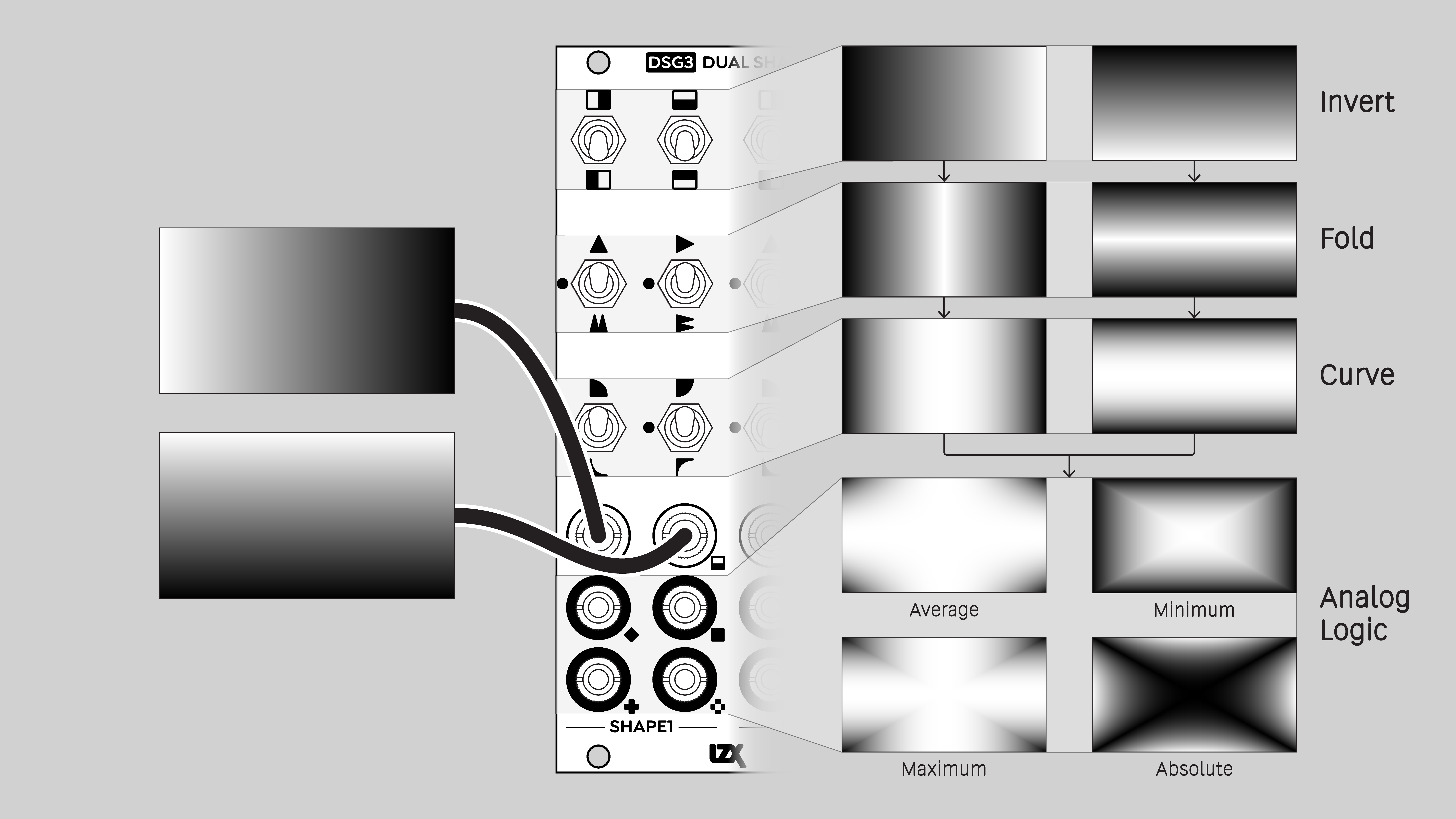
Invert
Reverse the input values. An input range from 0 to 1 gives an output range from 1 to 0. For a video image, this is a photo negative effect.
Fold
Precision full-wave rectification. Convert ramps/sawtooths to triangle waves. Double or quadruple the frequency of oscillators. Apply solarization and color cycling effects to images.
Fold 1 doubles the frequency of the signal, Fold 2 multiplies it by four.
Curve
Apply a logarithmic or exponential function. For a video image, this means changing the contrast curve, emphasizing the light or dark values. That's also known as a gamma adjustment. Values of 0 and 1 are not affected.
For a low frequency control signal, logarithmic or exponential curves cause animation to speed up or slow down in the low or high value ranges.
Logarithmic
Emphasize the higher values / lighter tones. Apply a gamma adjustment of 2.0.
A low frequency control signal moves faster in the low value range, and slower in the high value range. In animation terms, a "fast in, fast out" of a low value, and a "slow in, slow out" of a high value.
Exponential
Emphasize the lower values / darker tones. Apply a gamma adjustment of 0.5.
A low frequency control signal moves slower in the low value range, and faster in the high value range. In animation terms, a "slow in, slow out" of a low value, and a "fast in, fast out" of a high value.
Video Tutorials
3 Patches for DSG3
presented by Johnny Woods
LZX DSG3: Video Synth Tools & Techniques
presented by Aaron F. Ross
Example Patches
Self-patching Shapes in series
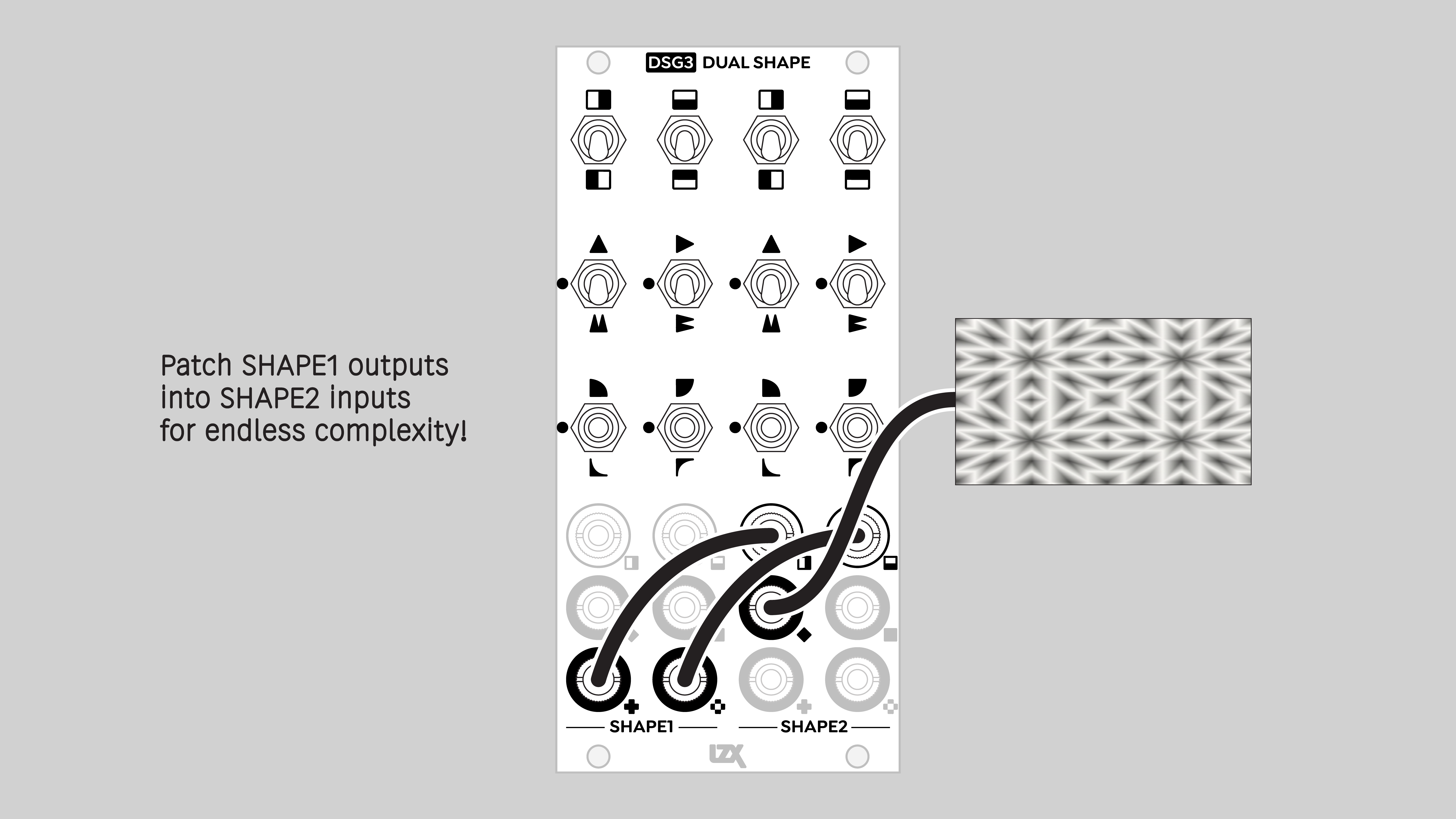
Hard-edged figures with a key generator / comparator
Installation
Requirements
- EuroRack enclosure
- 12V DC or EuroRack power supply
- 2.1mm DC barrel power cable or a EuroRack power cable (both options included)
- Four M2.5 x 6mm mounting screws, or screws provided or specified by the enclosure manufacturer
- #1 Phillips head screwdriver, or hand tool provided or specified by the enclosure manufacturer
Procedure
- Power off and disconnect the EuroRack enclosure's power supply and any attached DC adapters.
- Connect either the EuroRack Power Cable or the DC Barrel Power Cable to the module. Do not connect both Eurorack and DC Barrel power.
- Ensure that no mounting screws are in any holes in the area where you wish to mount the module.
- Carefully test fit the module with its attached power cable in the open space in the EuroRack enclosure. If it is obstructed by the enclosure or any internal assemblies, abort this procedure.
- Connect the disconnected end of the power cable to the power supply.
- Connect the sync cable to a sync source or the last module in the sync chain.
- Mount the module to the EuroRack rails using all mounting holes.
- Store the unused cable along with the product box in a safe location.
- Power on the EuroRack enclosure and start patching.
Full Specifications
| Connectors | Controls | |||||||||||||||||||||||||||||||||||||||||||||||||||||
|---|---|---|---|---|---|---|---|---|---|---|---|---|---|---|---|---|---|---|---|---|---|---|---|---|---|---|---|---|---|---|---|---|---|---|---|---|---|---|---|---|---|---|---|---|---|---|---|---|---|---|---|---|---|---|
 |
|
|
Technical Data
| Manufacturer Part Number | 950055 |
| Mounting Width | 12 HP |
| Mounting Depth | 42 mm |
| Mounting Hole Count | 4 |
| Power Consumption | 12V @ 350 mA |
| Power Connectors | 16 pin EuroRack ribbon, 2.1mm DC barrel |
| Input Impedance | 1M ohms |
| Output Impedance | 75 ohms |
| Input Protection Range | +/-20V |
| Input Clipping Range | +/-2.5V |
| Output Range | +/-2.5V |
| Included | DC barrel power cable, EuroRack power cable, RCA sync cable |
| EuroRack Power Cable Type | 16-pin |
| EuroRack Power Cable Length | 25 cm |
| DC Barrel Power Cable Length | 25 cm |
| RoHS Compliance | Manufactured with lead-free processes. |
| Video Sync | Rear RCA in & out |
Maintenance
Keep your module free of dust and debris by performing periodic cleaning. Spots may be cleaned from the frontpanel with a microfiber cloth and isopropyl alcohol or other electronics cleaner.
Hardware Revisions
The hardware revision code is printed on the circuit board visible from the rear of the module.