Swatch
Overview
Swatch is a powerful and innovative tool for manipulating color in ways that are difficult or impossible in the traditional RGB color space of a video synth. Technically, Swatch is a bidirectional color space converter. Creatively, we can think of it as a two-way color space portal. It opens up a color space called YIQ that has never before been fully accessible in a video synthesizer.
The introduction of Swatch has profound artistic implications. Swatch makes it possible to manipulate color in many unique and spectacular ways. Suddenly, all existing single-channel processing modules effectively work in color. In combination with support modules such as Proc, the intuitive, familiar HSV color system of Hue, Saturation, and Value is available. A wide range of novel color effects can be achieved.
Swatch doesn't apply to every patch. The traditional RGB color space is alive and well, and still has its characteristic advantages. But Swatch opens up a fantastic new range of visual possibilities, and once it's in your system you will probably find that you use it more often than not.
Features:
- Convert RGB to YIQ
- Separate luminance from chrominance
- Invert, swap, or double amplitude of IQ channels by self-patching
- Pick colors in intuitive YIQ space with Proc
- Combine and process YIQ channels through other modules
- Convert YIQ to RGB
Legacy
Swatch is unprecedented. Nearly all video synths have traditionally operated in the RGB color space. This is because RGB is the simplest to design, and because human color vision works on a tristimulus system. Our retinas have three types of photorecepting cone cells, each sensitive to a range of light wavelengths centered on red, green, or blue.
In the analog synth domain, exceptions to the RGB system are historically extremely rare. This is why video artists have often valued and employed outboard processing amplifiers with HSV controls. But it's not practical to insert an external proc amp in the middle of a modular synth patch. You'd need another pair of encoder and decoder modules, and probably another time base corrector. Moreover, proc amps are almost exclusively standard definition, ruling out fully HD workflows.
The Visionary series Colorspace Mapper and Expedition series Mapper modules employ some of the same concepts as Swatch. They provide outputs in the YUV color space, which is nearly identical to the YIQ color space of Swatch. But those legacy modules are functionally very different from Swatch. They accept signals representing Hue, Saturation, and Value, and convert those triads to YUV and RGB color components. This is great for certain applications, but it's a one-way ticket. There's no way to, for example, process a color image using HSV controls. But Swatch is a bidirectional color space converter, providing the means to make a round-trip through YIQ space, and by extension, HSV space, and back to the RGB space required by the encoder.
Key Specifications
| Parameter | Value |
|---|---|
| Mounting Width | 8 HP |
| Power Consumption | 12V @ 100 mA |
| Power Connectors | 16 pin EuroRack ribbon, 2.1mm DC barrel |
| Included | DC barrel power cable, EuroRack power cable |
| Video Sync | None |
System Integration Advice
Swatch is an essential module for any system except the very smallest. Controlling color is, of course, a fundamental "component" of video synthesis. Without Swatch, some common color correction operations aren't possible. For example, Swatch is a requirement for adjusting saturation without affecting hue or value. RGB color space simply doesn't allow that. Adjusting any of the red, green, or blue channels affects all three HSV parameters. Swatch is most critical when processing external video, but it also applies to patterns and images generated within the synth.
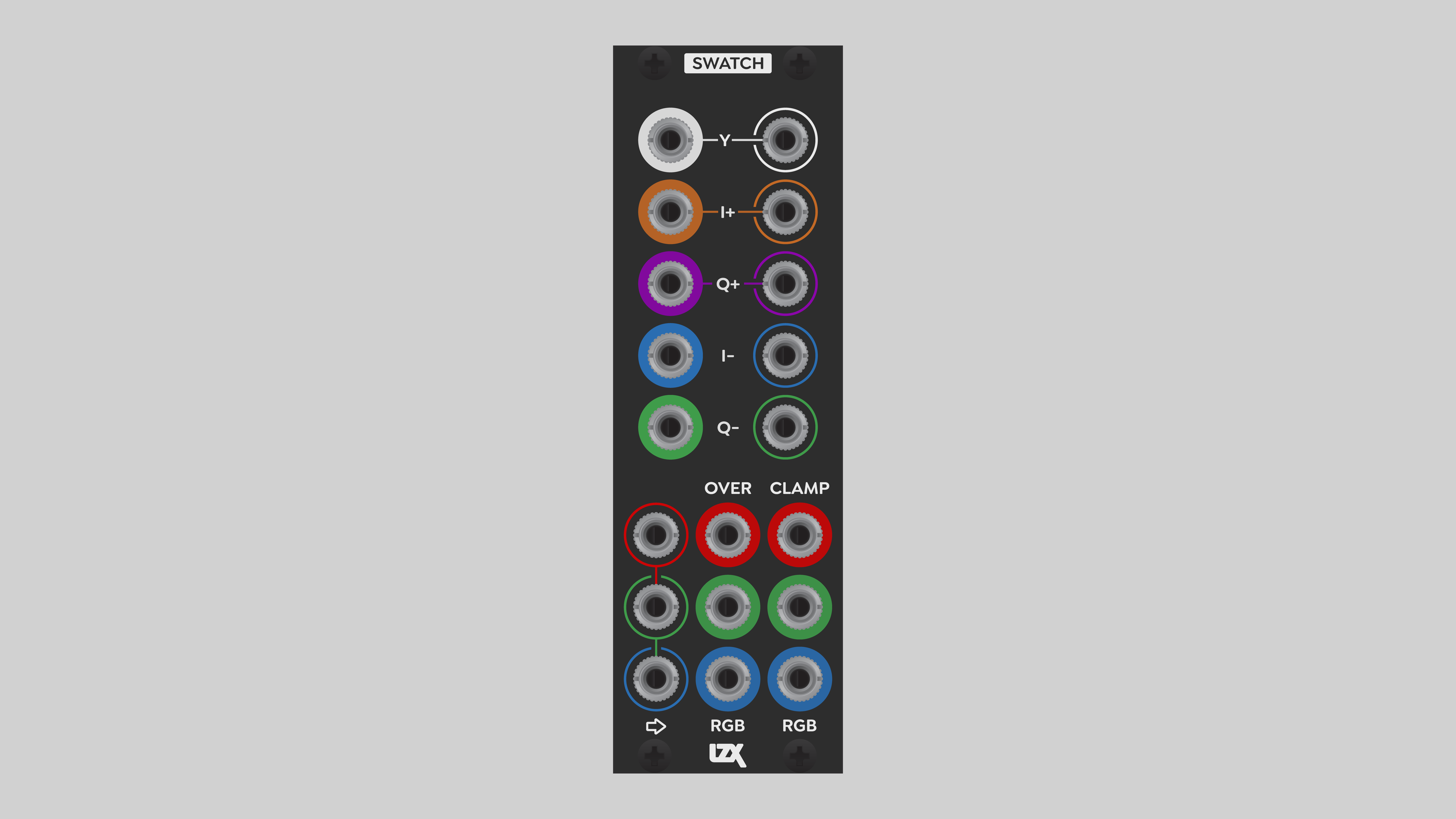
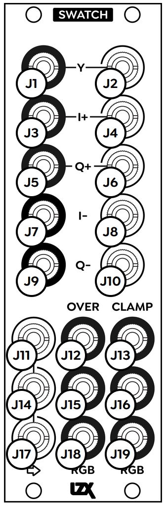
Connectors
The internal signal flow of Swatch is clockwise, starting from the lower left. As explained below, some, but not all, of the jacks are internally self-normalled. This allows a signal to flow through some or all of the color conversion stages.
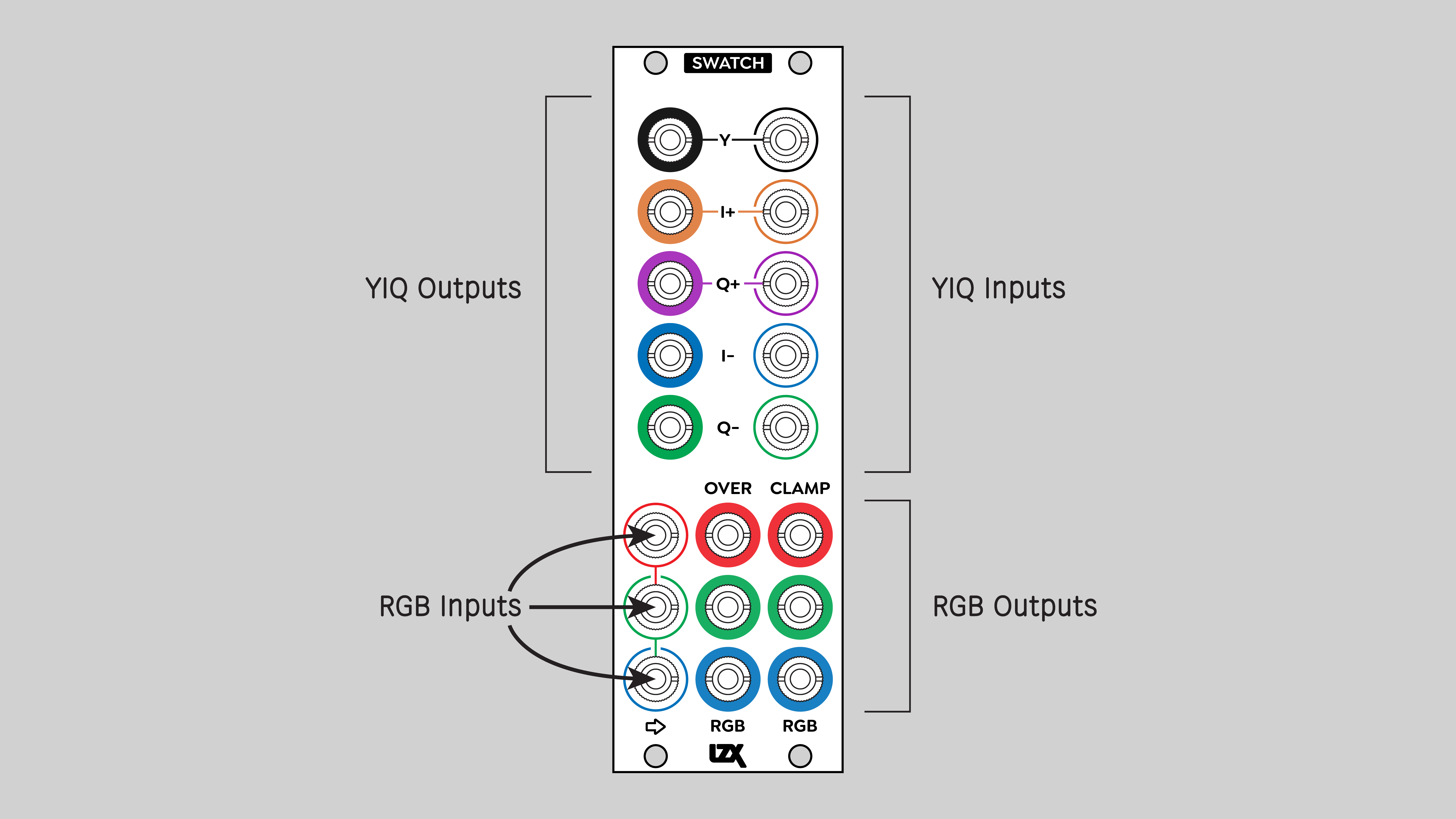
RGB Inputs
RGB inputs are found in the lower left corner. The RGB inputs are internally self-normalled. A signal patched into an RGB jack will also flow to the inputs below it.
Conventional usage of Swatch is to patch the red, green, and blue components of a video image into the respective RGB inputs of Swatch. But as always, feel free to go crazy and patch whatever weirdness you want into the RGB input jacks.
YIQ Outputs
RGB inputs are converted to YIQ components and output from five jacks on the upper left. Y is luminance, and I and Q are the color difference channels, described in the Operation section below. I and Q outputs come in two flavors, positive and negative. I+ and Q+ are the color difference channels transcoded from the incoming RGB components. I- and Q- are phase inverted versions of the color difference channels. The inverted color channels provide immediate creative possibilities by merely patching Swatch to itself. Double the saturation, invert the chrominance, or mutate color in unfamiliar ways. For details, check the Example Patches section below.
Color coding of the YIQ jacks indicates the actual colors of those components. Positive I is orange, positive Q is purple. Negative I is blueish cyan, negative Q is yellowish green. None of the raw IQ colors exactly line up with RGB primaries.
The inputs and outputs of Swatch are phase-aligned with high precision. This is necessary because any small deviation in the phase of the color channels would result in a hue shift. No matter what, you won't see Swatch introduce any undesired change in tint.
YIQ Inputs
On the upper right of the module are five YIQ inputs. Anything patched into any of those inputs is converted to RGB and appears at the RGB outputs below. For example, patching static voltages from Proc into the YIQ inputs makes Swatch into an intuitive color picker. Or patch one or more of the YIQ outputs to other modules, then return those signals back to the Swatch YIQ inputs.
YIQ signals can be routed through different modules without introducing obvious horizontal misalignment. For example, let's say we send Y through one module, and I and Q through some other module. The two modules have different delay times, knocking the components out of horizontal registration. Luckily, due to the limitations of our vision, only an extreme misalignment would be visible. If registration is off by a few pixels, it will probably go unnoticed.
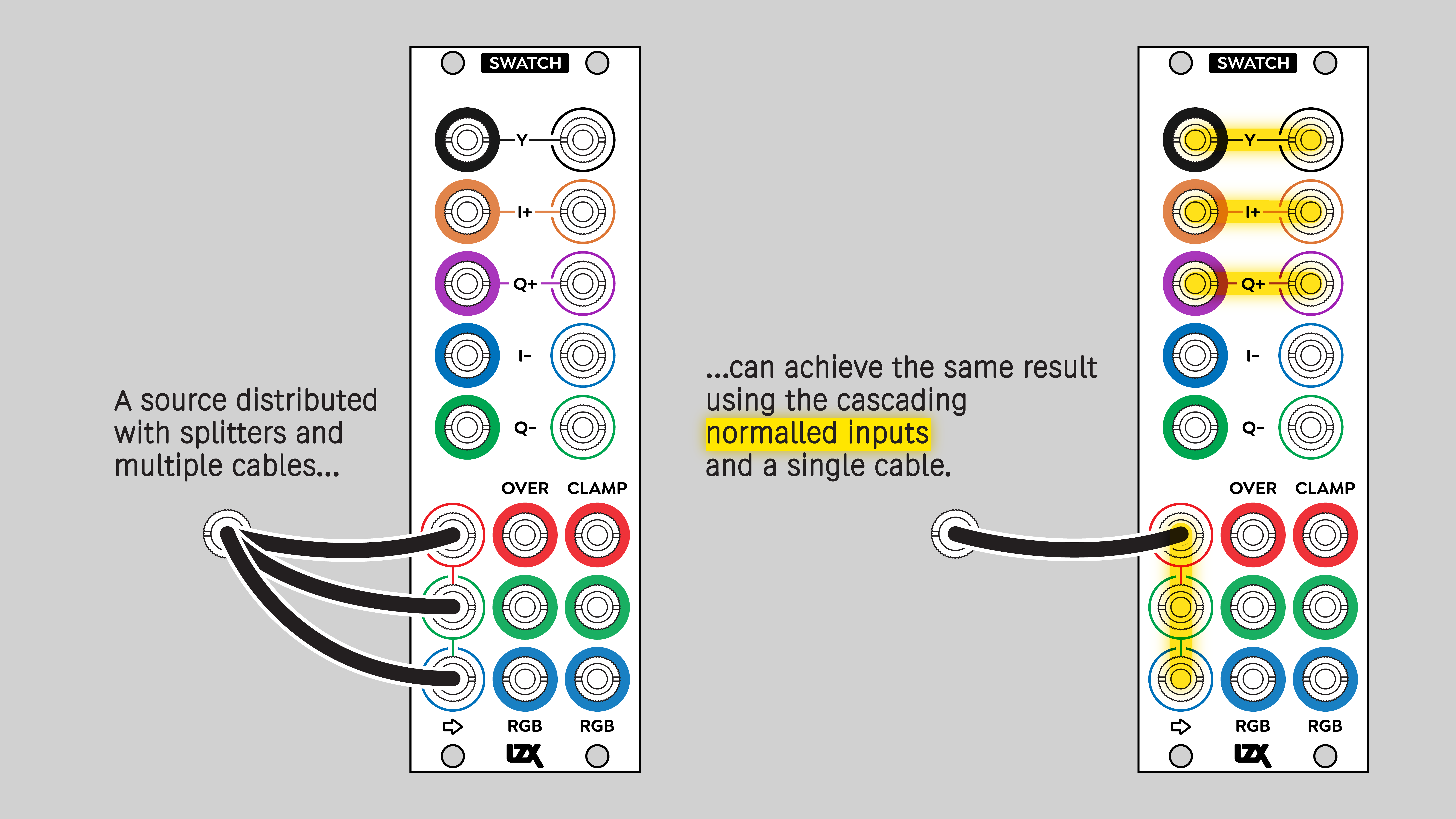
Some of the YIQ inputs are internally self-normalled to their respective outputs on the upper left. Y, I+, and Q+ are self-normalled. I- and Q- are not. The internal normalling means that if nothing is patched into the YIQ inputs, they will receive signals from the corresponding YIQ outputs. In that case, the signals appearing at the RGB outputs below are completely unaltered from the signals patched into the RGB inputs. In the absence of anything patched into YIQ inputs, the signal flow within Swatch is:
In that scenario, Swatch would effectively do nothing to the incoming RGB signals. Significantly, colors pass through Swatch with near perfect fidelity. RGB components go through multiple stages of buffering and two stages of color space conversion, with no visible alteration. You decide exactly how color is mutated.
The I- and Q- inputs are not internally normalled to the I- and Q- outputs. Anything patched into the I- and Q- inputs is subracted from the I+ and Q+ inputs. This enables simple operations such as doubling the saturation, and more complex operations such as layered modulation of color channels by utilizing more than two IQ inputs at once.
The internal operations of the Y, I and Q inputs look like this:
RGB Outputs
Swatch features two sets of RGB outputs: Over and Clamped. These give us options in situations arising from the differences between YIQ and RGB color spaces. YIQ can represent a greater range of colors than RGB. The technical description of this is that YIQ has a wider gamut.
For an introduction to YIQ, see the Operation section below.
Swatch gives us options for resolving the mismatch between YIQ and RGB gamuts. It's trivially easy to specify impossible colors by sending moderately high or low voltages into the YIQ inputs of Swatch. The expected range of the I and Q inputs is +0.5 to -0.5 volts. Anything above or below that is outside of the YIQ gamut. But even within the +0.5 to -0.5 range, it's possible to specify colors that are outside of the RGB gamut.
So what are our options? The Clamped outputs simply discard any RGB values outside of the 0 to +1 voltage range of LZX modular video. That helps to ensure predictable results in later stages of the patch. But it does clip anything out of RGB gamut.
If your YIQ levels are "hot", then you might want to use the Over outputs to make sure that you don't lose any picture information when transcoding to RGB. The Over outputs don't clip the RGB signals, they just pass the raw values even if outside the 0 to +1 range. To prevent any clipping of "hot" YIQ signals, send the Over outputs through another module to attenuate / bias the RGB components into the 0 to +1 volt range. The ideal module for that is Proc.
Operation
Introducing YIQ
Swatch is a bidirectional color space converter. It transcodes RGB to YIQ and YIQ to RGB, with no color shifting or distortion.
The illustration below shows the difference between the two color spaces. It's derived from the display of a vectorscope, a hardware or software tool for analyzing video color. I and Q are the vertical and horizontal axes of the color space, respectively. Any combination of hue and saturation can be represented by a point on this Cartesian plane: a pair of signed I and Q values ranging from +0.5 to -0.5.
Even though I and Q cover the entire square, anything outside of the circular area is technically "illegal": it can't be recorded or broadcast. Although I and Q values can theoretically represent a color outside the circle, in reality, that color doesn't exist. And the practical limits of RGB video are even more restricted. The effective gamut of RGB is limited to a roughly hexagonal area in the center of the vectorscope.
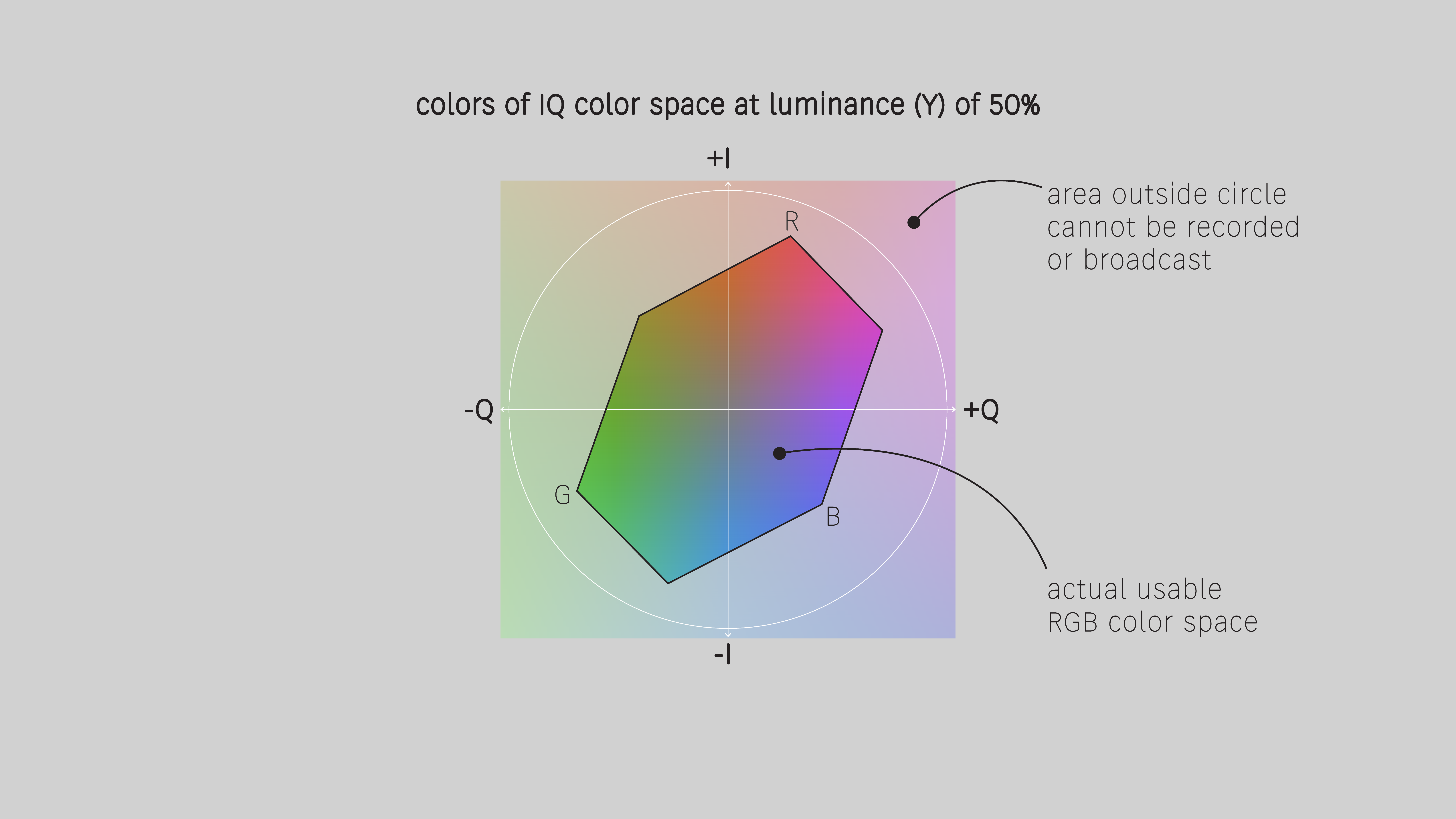
Colors on the vectorscope are also commonly enumerated with a more familiar pair of values: an angular value representing phase or hue, and a scalar value representing intensity or saturation. Hue is the angle around the circumference of the circle, and saturation is the distance away from the center.
The YUV Family
YIQ is a color space nearly identical to the familiar analog component video format, YPbPr, and its digital equivalent, YCbCr. All of these systems fall under the generic name YUV. Y is luminance, and U and V are the color difference channels of red minus Y and blue minus Y.
YUV exists for several reasons, but one important one is lossless compression. YUV stores the same information as RGB, but uses less transmission bandwidth and storage. The original RGB channels go through some simple algebra, resulting in a new set of components: luminance and two color difference channels.
The table below shows how YUV is calculated, and the names of its channels as implemented in different video formats.
| Luminance (Y) | Color difference ch 1 | Color difference ch 2 | |
|---|---|---|---|
| Formula | 0.299R + 0.587G + 0.114B (see TBC2 documentation) | R - Y | B - Y |
| Generic name | Y | U | V |
| Analog composite & Y/C | Y | I | Q |
| Analog component | Y | Pb | Pr |
| Digital component | Y | Cb | Cr |
YIQ Orientation
The main difference between UV and IQ spaces is that the IQ coordinate system is rotated -33 degrees relative to UV. The coordinate system is aligned with human skin tones in order to prioritize them. The transmitted signal is most robust in the hue range of skin tones. The I axis is rotated to align with the hue of melanin, which is the same for everyone.
In the illustration above, I and Q are oriented parallel to the vertical and horizontal dimensions of the image. But on a vectorscope, the UV axes are aligned vertically and horizontally, and the IQ axes are rotated 33 degrees to the left.
Additionally, the I component carries a little bit more bandwidth than the Q component. Again, that's to prioritize skin tones. And that's why on some vectorscopes the I and Q axes are not displayed at right angles to one another.
In-phase and Quadrature
I and Q form the foundation of color in two common analog video formats: composite and S-Video (also known as Y/C). The IQ encoding scheme ensures full compatibility between black and white and color television.
The intials I and Q are derived from an exceptionally clever scheme of encoding both color difference values to a single value called chrominance or chroma. This is accomplished by modulating R-Y and B-Y difference channels with two sine waves. The sines are 90 degrees out of phase. I is the color component that uses an in phase sine wave, with a phase of zero. Q is the color component that uses a quadrature sine, that is 90 degrees out of phase with the I component. When these two sines are added, the result is chroma. At the receiving end, the separate I and Q color components are extracted by demodulating with a sine wave at the same frequency as the modulating sine.
Polarity
All analog color difference channels employ bipolar signals that can be positive or negative. Swatch is no exception. The I and Q inputs and outputs are all bipolar, with a range from +0.5 to -0.5. Some LZX modules can handle bipolar signals. Examples include Proc, SMX3, DSG3, PGO, and PRM. Modules designed primarily for picture signals may not support bipolar signals. For example, FKG3 will ignore negative voltages.
If you wish to pass I or Q through a solely unipolar module, you'll need to convert I and Q to unipolar by biasing it up +0.5 volts. Otherwise, half of the potential color information will be lost. Likewise, before patching a unipolar signal into the I or Q inputs of Swatch, it will need to be biased back down -0.5 volts.
Many modules can perform the function of biasing up or down to convert between unipolar and bipolar. Proc is one module that can do it. PGO may be a better choice, leaving Proc available for more artistic functions such as colorization.
Y or luminance is unipolar, with a voltage range of 0 to +1. Therefore if you want to patch Y into I or Q, or vice versa, you'll once again need to convert polarity by biasing 0.5 volts up or down. If you don't, you'll lose half of the potential information due to clipping.
Color Shift
One of the most basic operations we can perform on I and Q is shifting color in various directions. All we need to do is bias I and Q. Proc is the best tool for this, providing the ability to fine-tune color positioning in IQ space. This technique is rarely found in any other context. Only the most advanced digital color correction tools can do it.
Saturation
Saturation is the intensity of a color. Pastel colors are desaturated compared to more vibrant or intense colors such as the pure spectra of a rainbow.
In YUV color difference systems, saturation is encoded as the amplitude of the color channels. With Swatch, manipulating saturation is as simple as attenuating or amplifying I and Q.
Hue Rotation
Understanding how I and Q operate is essential to advanced Swatch patches. To rotate the hue of an image, use the following formulas:
Sine and cosine can come from a quadrature sine oscillator, or any device that can calculate sine and cosine voltages from a single value. LZX doesn't currently make a quadrature oscillator, but Syntonie offers the VU006, which outputs sines in the unipolar LZX video range of 0 to +1 volts.
To rotate hue in a continuous cycle, multiply VU006 outputs with I and Q using 2x Factors or 4x PRM. Then add and subtract those products using modules such as Sum/Dist, Proc, or 2x PGO.
Some multifunction Eurorack control modules provide the ability to output sine and cosine values calculated from any signal, such as a static or low frequency voltage. One example is Ornament & Crime with the Hemispheres firmware. The applet VectMorph accepts an arbitrary voltage and outputs two voltages that are 90 degrees out of phase.
Seeing the Matrix
One of the most spectacular uses of Swatch is matrix colorization, where we can map and combine any of the YIQ signals with one another. SMX3 is the tool for this. It's the same concept as matrix colorization in RGB: patch the color components into the top row of SMX3. Thanks to SMX3's internal normalization, the top input signals flow to the inputs below. Tweak the SMX3 pots to attenuate, amplify, or invert any color component routed to any other color component.
YIQ matrix colorization is especially interesting because we can use luminance as a color channel or vice versa. This gives a radically different palette of creative possibilities compared to RGB matrix mixing.
Due to the fact that Y is unipolar, and I and Q are bipolar, the outputs of SMX3 will need to be tweaked by Proc before going back into Swatch.
Video Tutorials
3 Patches for Swatch
presented by Johnny Woods
LZX Swatch: Video Synth Tools & Techniques
presented by Aaron F. Ross
Example Patches
Double Saturation
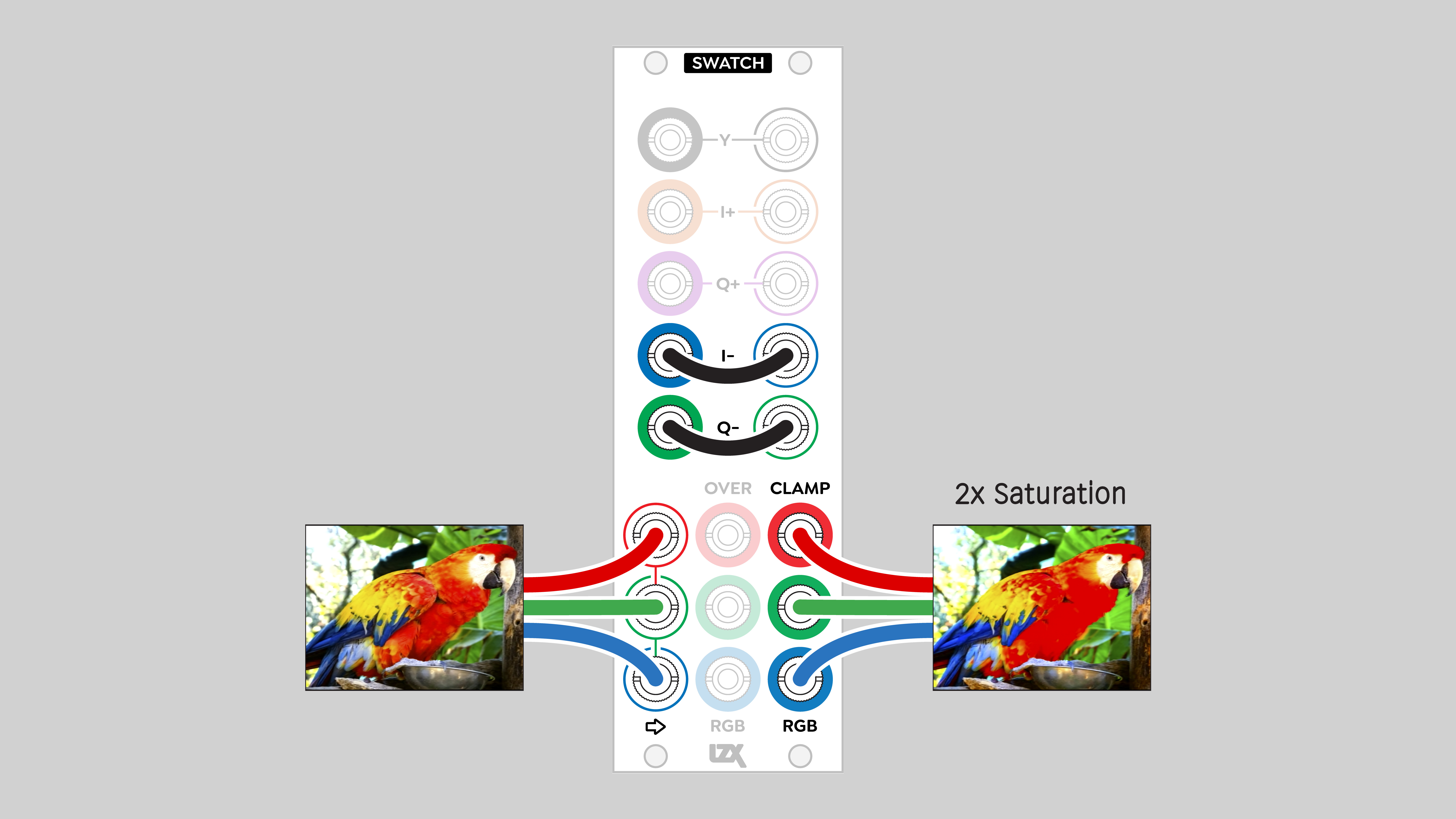
I- and Q- come out of their jacks already inverted. When patched into I- and Q-, those inverted signals are subtracted from I+ and Q+. We're subtracting a negative value. The result is adding I and Q to themselves.
Invert Chrominance (Chroma)
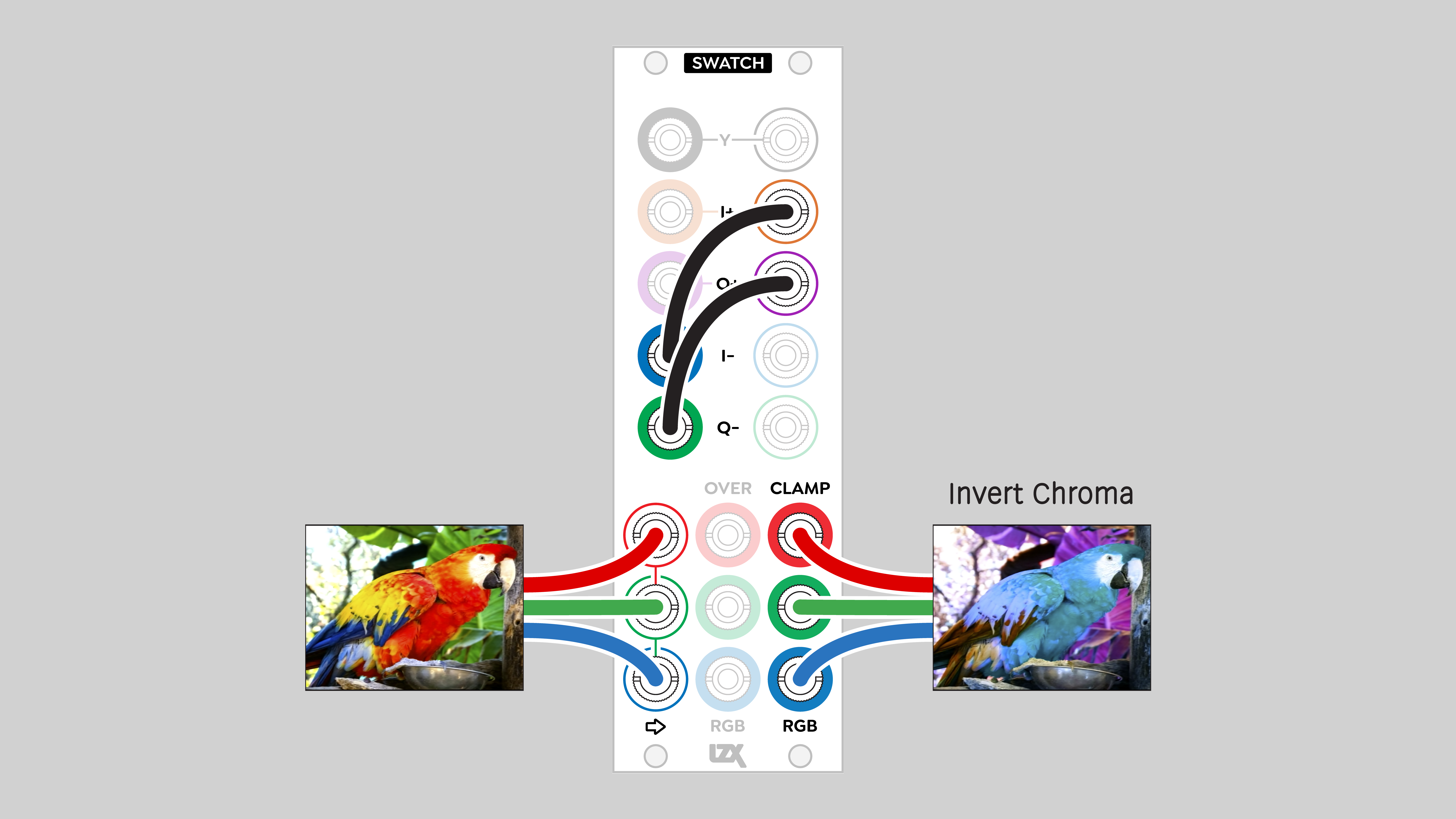
This is the effect of tweaking the Tint on an NTSC monitor as far as it can go... rotating the hue 180 degrees. In this case, we do it by flipping the signs of the I and Q coordinate axes. That has the effect of mirroring both I and Q around the other axis, which is mathematically the same as a 180 degree rotation.
Invert Luminance (Luma)
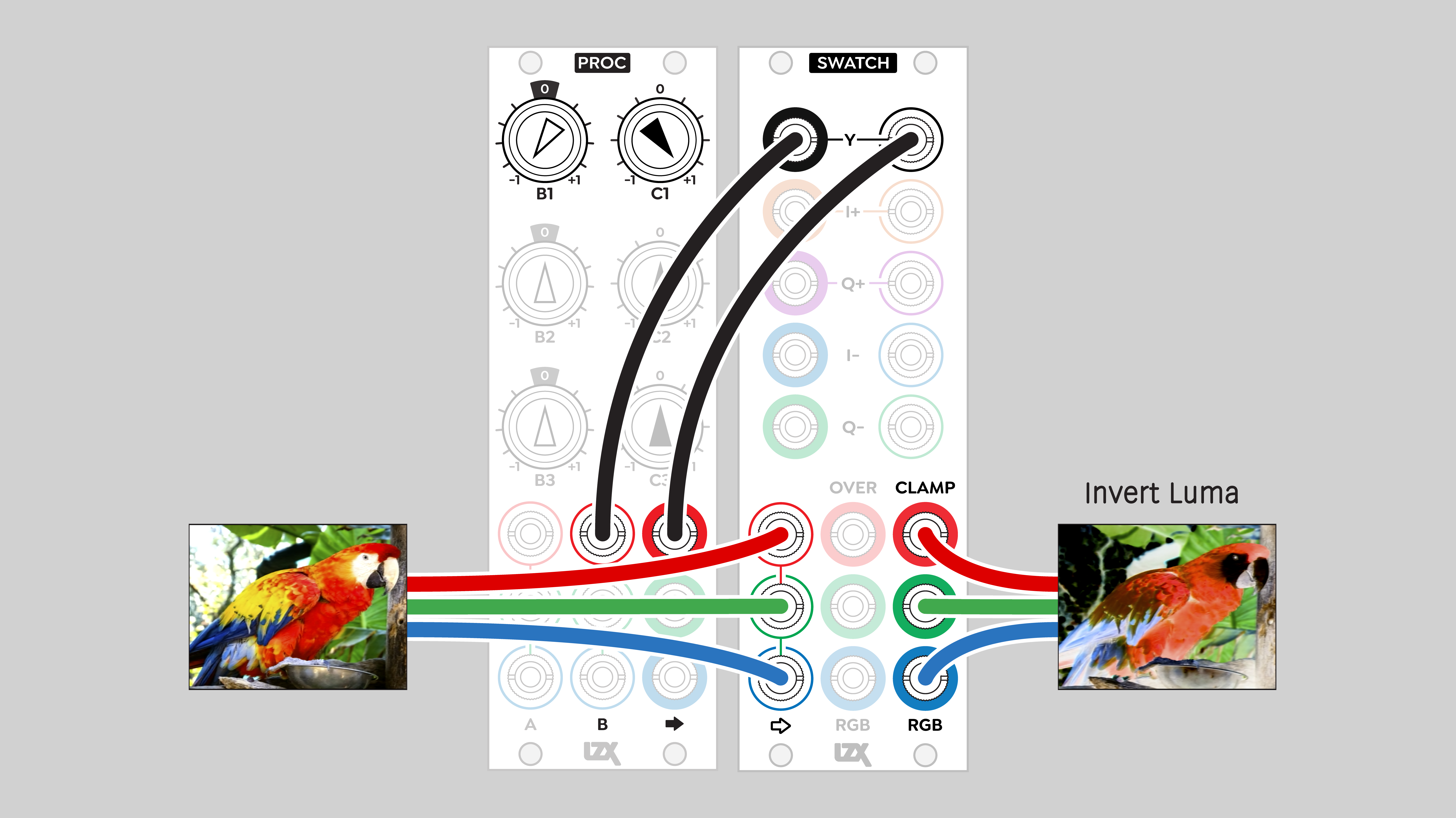
An otherworldly sight to behold, a photo negative with the original color untouched. Of course, many other modules such as DSG3 can invert a signal.
Sending luminance through a single channel processor such as Stairs or Ribbons essentially allows that module to operate in full color.
Posterize
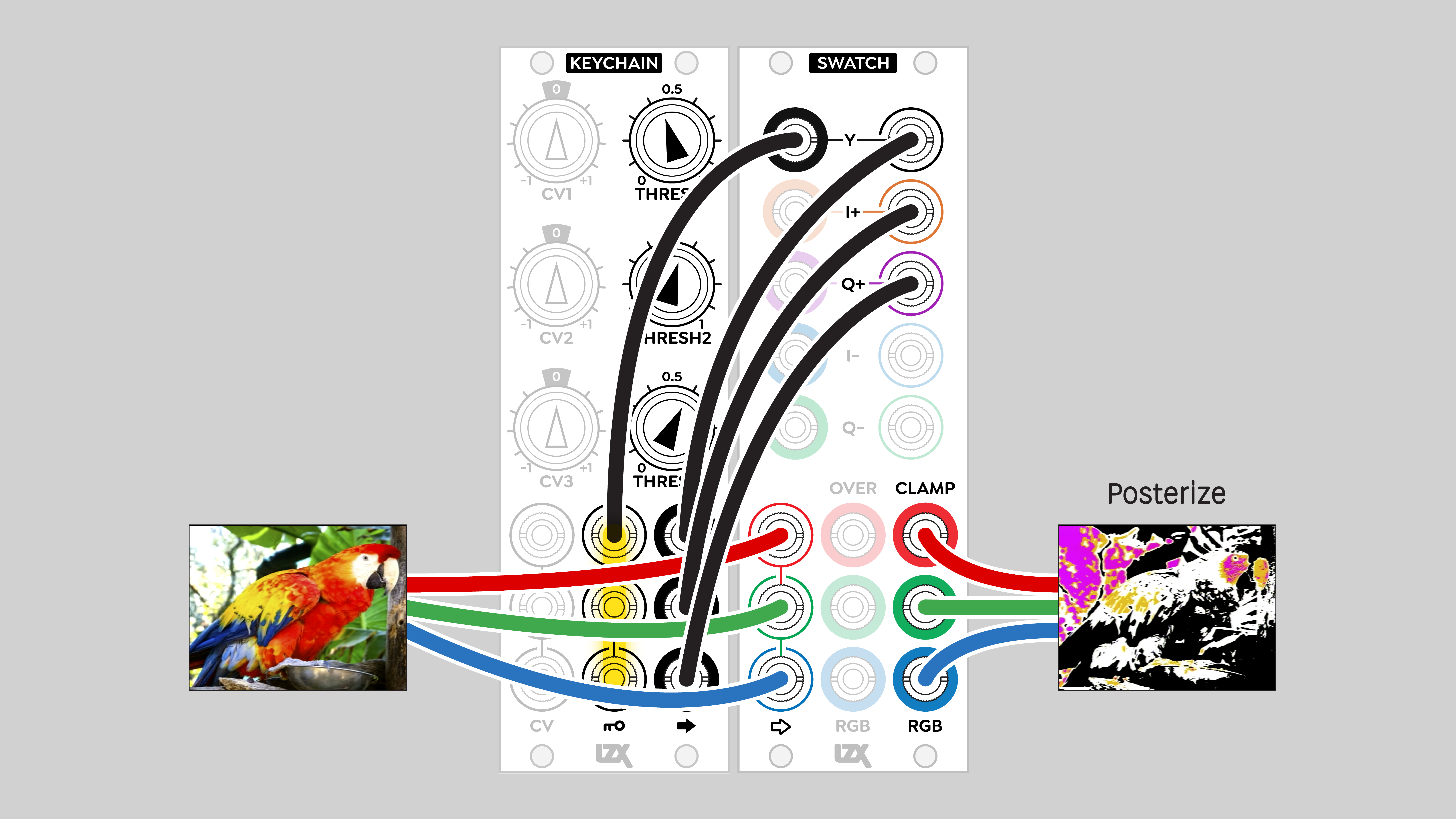
This is a simple posterization patch. Add Proc after the Keychain outputs to art direct the color scheme.
Pick YIQ Color
Proc's bipolar voltage sources make it possible to address any color in YIQ space.
Installation
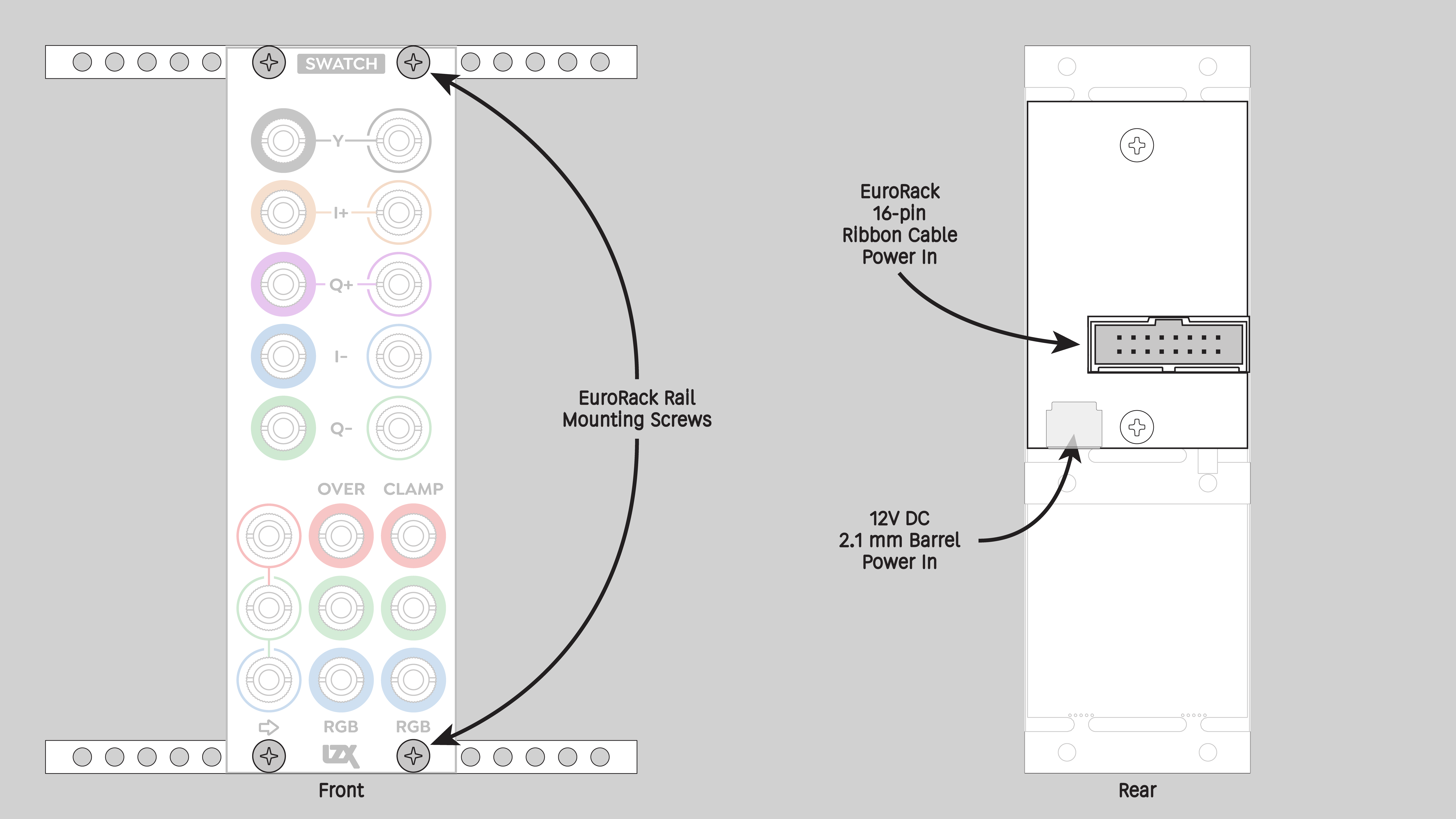
Requirements
- EuroRack enclosure
- 12V DC or EuroRack power supply
- 2.1mm DC barrel power cable or a EuroRack power cable (both options included)
- Four M2.5 x 6mm mounting screws, or screws provided or specified by the enclosure manufacturer
- #1 Phillips head screwdriver, or hand tool provided or specified by the enclosure manufacturer
Procedure
- Power off and disconnect the EuroRack enclosure's power supply and any attached DC adapters.
- Connect either the EuroRack Power Cable or the DC Barrel Power Cable to the module. Do not connect both Eurorack and DC Barrel power.
- Ensure that no mounting screws are in any holes in the area where you wish to mount the module.
- Carefully test fit the module with its attached power cable in the open space in the EuroRack enclosure. If it is obstructed by the enclosure or any internal assemblies, abort this procedure.
- Connect the disconnected end of the power cable to the power supply.
- Mount the module to the EuroRack rails using all mounting holes.
- Store the unused cable along with the product box in a safe location.
- Power on the EuroRack enclosure and start patching.
Full Specifications
| Front panel | Connectors | ||||||||||||||||||||||||||||||||||||||||
|---|---|---|---|---|---|---|---|---|---|---|---|---|---|---|---|---|---|---|---|---|---|---|---|---|---|---|---|---|---|---|---|---|---|---|---|---|---|---|---|---|---|
 |
|
Technical Data
| Parameter | Value |
|---|---|
| Manufacturer Part Number | 950054 |
| Mounting Width | 8 HP |
| Mounting Depth | 32 mm |
| Mounting Hole Count | 4 |
| Power Consumption | 12V @ 100 mA |
| Power Connectors | 16 pin EuroRack ribbon, 2.1mm DC barrel |
| Input Impedance | 1M ohms |
| Output Impedance | 75 ohms |
| Input Protection Range | +/-20V |
| Input Clipping Range | +/-2.5V |
| Output Range | +/-2.5V |
| Included | DC barrel power cable, EuroRack power cable |
| EuroRack Power Cable Type | 16-pin |
| EuroRack Power Cable Length | 25 cm |
| DC Barrel Power Cable Length | 25 cm |
| RoHS Compliance | Manufactured with lead-free processes |
| Video Sync | None |
Maintenance
Keep the module free of dust and debris by performing periodic cleaning. Spots may be cleaned from the front panel with a microfiber cloth and isopropyl alcohol or other electronics cleaner.
Hardware Revisions
The hardware revision code is printed on the circuit board visible from the rear of the module.